Nanoporous silver microstructure for single particle surface-enhanced Raman scattering spectroscopy†
Kanet Wongravee*a,
Harnchana Gatemalaa,
Chuchaat Thammacharoena,
Sanong Ekgasita,
Sanpon Vantasinb,
Ichiro Tanabeb and
Yukihiro Ozakib
aSensor Research Unit, Department of Chemistry, Faculty of Science, Chulalongkorn University, Bangkok, 10330, Thailand. E-mail: kanet.w@chula.ac.th; Fax: +66 2218 7585; Tel: +66 2218 7589
bDepartment of Chemistry, School of Science and Technology, Kwansei Gakuin University, Sanda, Hyogo 669-1337, Japan. E-mail: ozaki@kwansei.ac.jp; Fax: +81 79 565 9077; Tel: +81 79 565 8349
First published on 19th November 2014
Abstract
The potential of a nanoporous Ag microstructure (np-AgMs) for use as a single particle for surface-enhanced Raman scattering spectroscopy (SERS), with the added advantages of being easy to manipulate and reusable, was successfully demonstrated. The np-AgMs with interconnected pore and controllable pore size were fabricated from symmetric hexapod AgCl via a galvanic replacement reaction in NaCl solution with zinc (Zn) as the sacrificed metal. The clean surface of np-AgMs enables rapid surface functionalization with easy handling and sample preparation as no particle aggregation occurs. The SERS acquisition spots on the np-AgMs can be visually selected using a normal Raman microscope. SERS spectra of p-aminothiophenol (PATP) with a concentration range of 10−8–10−3 M can be achieved. The position-dependent enhancement of np-AgMs was expendably evaluated. The signal-position correlation was confirmed by electric filed enhancement obtained from Finite-difference time-domain (FDTD) calculation. In addition, the highly stable substrate showed insignificant loss of the enhanced Raman signal after several cycles of chemical re-generation. Finally, the potential application of np-AgMs in label-free detection of biomolecules including hemoprotein, protein without chromophore and DNA strains at low concentration of 500 μg mL−1 was demonstrated.
1. Introduction
Noble metal nanostructures can generate surface plasmon polarization as they contain high mobility electrons which give rise to electron oscillation on a metal surface. An intense electro-magnetic field can be obtained in their vicinity.1 This phenomenon leads to the enhancement ability of Raman spectroscopy when analyte molecules are in a “hot spot” of a plasmonic nanostructure.2 This offers a great opportunity to use a Raman scattering technique for trace analysis of various molecules. The use of metal nanostructures for enhancing Raman scattering signal is called “Surface Enhanced Raman Scattering (SERS)”. In recent decades, a large number of research groups have contributed to fabrication of various SERS substrates to enhance the Raman signal of distributed target analytes.3,4 In particular, silver (Ag) and gold (Au) metal nanostructures have been used because they have high plasmonic activities in the range of visible to near infrared regions. SERS substrates designed from the metals make use of as many different laser wavelengths as possible.5,6Although recently there has been extensive research focusing on fabrication of SERS substrates, there are still difficulties in making these commercially viable analytical tools. Firstly, uniformity of enhancement efficiency across a substrate cannot be ensured because the level of metal nanoparticle aggregation is difficult to control and measure.7 Therefore, a hotspot presented on a substrate can be generated with high variations in performance. Secondly, determination of the sensing region is complicated as the hotspots are in the nanometer-scale and cannot be simply visualized under a Raman microscope. Using an ‘invisible’ hotspot, detection of an analyte with small volumes in the sub-micro-L or nano-L range is difficult to achieve. To overcome these disadvantages, a plasmonic structure that is uniform and reproducible across the substrate area and with region of detection that can be simply determined under a Raman microscope is required. Moreover, the developed substrate should minimize the volume of analytes and provide easy handling, at least at the micrometer level. Enhancement efficiencies of nanostructures of varying sizes, shapes and interconnectivity (e.g. rods, hexagons, cups, stars, dendrites, films, flowers, urchin, etc.) have been monitored in recent years.8–13 It was found that a nanostructure with a particle size of approximately <100 nm is preferable for development of an effective SERS substrate.14 There have been several studies on interconnection of individual nanoparticles using sophisticated lithography techniques.15–17 However, these studies are limited, involving multi-step chemical processes, and manipulation of detection under a Raman setup is complicated. Therefore, development of a simple fabrication process for effective nanostructure SERS substrates that can be manipulated easily is desirable.
Nanoporous metals have attracted extensive attention according to their interesting physical, chemical and mechanical properties.18,19 These unique properties have led to them being used in a wide range of applications including electrodes, catalysts, sensors and supercapacitors. Most nanoporous metals have been fabricated either by dealloying a solid-solution,20,21 lithography,22,23 or a chemical redox reaction.24–26 However, these techniques involve several precursors which are complicated to remove at the end of process. A few reports have been made of fabrication of microstructures with nanopores on the surface to be used as single particle SERS substrates. Gilbert et al.7 reported fabrication of nanoporous Ag-based metallic glasses via a dealloying process. Mettela et al.27 described a fabrication process of nanocrystalline Ag microflowers to be used as a versatile SERS platform to detect biological analytes with a high degree of reusability. According to our previous study,28 various AgCl microstructures, including octapods, fishbone pods, hexapods and concave octahedrons, are formed using a controllable and selective precipitation by addition of Cl− ions to a [Ag(NH3)2]+ complex. By manipulating the seed morphology and the growth environment, complex AgCl microstructures can be selectively fabricated with hexapods as the major structure. The surface of the fabricated AgCl can be reformulated into silver nanoparticles (AgNPs) by partial photo-reduction. This generates a porous-like structure on the particles.
In this study, we extend our previous research by exploring the potential of the fabricated AgCl microstructure as an individual particle SERS substrate. To obtain a nanoporous Ag microstructure (np-AgMs) with a controllable pore size, the galvanic replacement of AgCl using a metal, e.g. zinc (Zn), is reported. By comparison with other preparation methods,20–27 the fabricated np-AgMs are of low cost, easy to freshly prepare in less than 10 minutes, and the overall size of the obtained structure can be handled easily under a Raman microscope. Full characterizations of the fabricated nanoporous Ag microstructure, including physical morphology and chemical composition, were made using a scanning electron microscope (SEM), energy dispersive X-ray spectrometer (EDS) and X-ray scattering (XRD). The results show that the np-AgMs particles are on a very clean surface. This is because of the lack of any capping agents as precursors. The efficiency as a SERS substrate was investigated by measuring the SERS of several analytes using only a tiny volume (1 μL) at submicro-molar concentrations. Analytes including p-aminothiophenol (PATP) and several biological analytes (deoxyribonucleic acid, lysozyme, cytochrome C and catalase) were chosen to validate SERS activity of the fabricated np-AgMs. Importantly, the np-AgMs are recyclable and can be used several times without a loss in enhancement activity. In this paper, the hexapod structure was selected because of its pore size distribution and uniformity. However, a variety of structures could be synthesized using the same protocol, and could be used as effective SERS substrates in appropriate circumstances.
2. Experimental section
Materials and chemicals
Silver nitrate (AgNO3), sodium chloride (NaCl) and ammonium hydroxide solution (NH4OH 25% w/w) with analytical grade were purchased from Merck. Deionized water was used to dissolve the reagents. The p-aminothiophenol (PATP), lysozyme, and crytochrome C were purchased from Sigma-Aldrich Co., Ltd., while catalase and deoxyribonucleic acid from Salmon sperm were purchased from Wako Co., Ltd. To prepare the analyte solutions, distilled ethanol was used to dissolve PATP and a phosphate buffer (PB) solution of NaH2PO4 and Na2HPO4 (0.1 M, pH 7.0) purchased from Wako Co., Ltd. was used to dissolve the biological samples throughout the study.Silver chloride hexapod structure
A hexapod silver chloride structure (6pAgCl) was selectively synthesized via a controlled crystallization method by Cl− induced precipitation on a silver ammine complex ([Ag(NH3)2]+). The preparation method for fabricating 3D AgCl microstructures is discussed fully elsewhere.28 Briefly, a solution of AgNO3 (0.1 M, 5 mL) was mixed with NH4OH solution (5.31 M, 4.7 mL) to obtain a clear solution of silver ammonium complex ([Ag(NH3)2]+). The prepared silver ammonium complex was quickly injected into a NaCl solution (1 M, 90 mL) under vigorous stirring at room temperature for 5 minutes. Sponge-like colloids were generated. The precipitated colloids were softly separated, washed with deionized water, then absolute ethanol two times each, and dried in air.Nanoporous Ag microstructure synthesis by galvanic replacement on a 6pAgCl microstructure
A plate of zinc was immersed and contracted to the obtained 6pAgCl in a sodium chloride solution as the electrolyte. The concentration of sodium chloride was varied from 0 to 1 M to investigate the grain and pore size on the galvanized silver microstructure. The galvanic replacement reaction was carried out for 30 minutes in ambient conditions. Subsequently, the precipitants were separated, washed by deionized water and distilled ethanol two times each, and dried in air. A schematic of the overall synthesis of 6pAgCl and the nanoporous Ag microstructure is shown in Scheme 1. | ||
| Scheme 1 Schematic diagram illustrating the synthesis of the 6pAgCl microstructure and np-AgMs via galvanic replacement in NaCl solution with a zinc (Zn) plate. | ||
Characterizations
The morphological structure of the obtained 6pAgCl and nanoporous Ag microstructure was observed using a scanning electron microscope (SEM, JEOL JSM-6510A) operating at 20 kV under a high vacuum mode with a secondary electron image (SEI) detector. The elemental composition analysis of the material was investigated using a built-in energy dispersive X-ray spectrometer (EDS). The X-ray diffraction patterns were collected by an X-ray diffractometer (Rigaku D/MAX-2200) with a scanning rate of 0.02 deg min−1, using Cu Kα irradiation (0.154 nm, 40 kV, 30 mA), and the diffractograms were recorded in the 20–80° region.Nanoporous Ag microstructure for SERS measurements
A solution with 1 mg of nanoporous Ag microstructure in distilled ethanol 2 mL was prepared and sonicated for 1 minute. Before each SERS measurement, a SERS substrate was prepared by pipetting 10 μL of the solution onto the micro cover glass (Matsunami Glass Ind. LTD, Japan) and drying at 80 °C for an hour to remove the solvent (ethanol). An amount of 1 μL of each analyte was dropped onto the prepared substrate for carrying out the SERS measurement. SERS spectra were measured using a Photon Design Nanostar NFRSM800 with a 514.5 nm line of diode-pumped solid-state laser (Cobolt FandangoTM, Cobolt, Sweden) as an excitation source. An objective lens of 90× with a laser spot size (spatial resolution) ∼1 micron was used in the study. The typical laser power used was 0.1 mW and exposure time for measuring was 10 s.3. Results and discussion
From Scheme 1, a colorless solution of complex [Ag(NH3)2]+ was prepared from the mixed solution of AgNO3 and NH4OH solutions. White sponge colloids of 6pAgCl gradually precipitated after quickly injecting the prepared solution into the NaCl solution, following the chemical equation| [Ag(NH3)2]+(aq) + Cl−(aq) + 2H2O(l) → AgCl(s) + 2NH4OH(aq).29 |
It is noted that the concentrations of all reagents used to fabricate the AgCl microstructure strongly affected the morphology (size and shape), as discussed in our previous study.28 In this study, only the experimental condition which gave the majority of hexapod AgCl microstructure is reported, as it is simple to control and provides the most uniform structures. For galvanic replacement, the precipitated 6pAgCl was smoothly placed on the Zn plate with a drop of NaCl solution. After incubation for 30 min, the initial white-gray precipitants were transformed to a darker grey color suggesting that the galvanic reaction was successfully achieved.
Fig. 1A and B shows the SEM micrographs of 6pAgCl and the galvanized Ag microstructure, respectively. Under low magnification, the main structure of the particle before and after galvanic replacement is the hexapod structure with a size of approximately 20 micrometers in the longest lateral length. However, under high magnification, the surface of the particle is dramatically changed from a smooth to a porous structure after galvanization, but the main structure is maintained as hexapods. This suggests that the galvanic replacement process using the Zn plate is nonviolent, as it only affected the surface and did not obliterate the main structure.
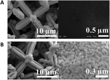 | ||
| Fig. 1 Low and high magnifications of SEM micrographs for (A) 6pAgCl and (B) nanoporous Ag microstructure. | ||
The concentration of sodium chloride used as an electrolyte during the galvanic replacement process was varied from 0 to 1 M to investigate the grain size distribution. SEM micrographs of the obtained nanoporous Ag microstructure including the distribution of grain size are shown in ESI Fig. S1.† There are several articles reporting that halide ions can help initiate the galvanic replacement process,30 but in our case there were no significant differences on the surface structure and grain size distribution of np-AgMs after galvanization. The average grain size is 60–65 nm with interconnected nanopores in all conditions. However, AgCl can re-precipitate out and interfere unfavorably with the galvanized Ag. Therefore, a concentrated NaCl solution (1 M) was used in our study to prevent re-precipitated AgCl and to accelerate the galvanic reaction as chloride ions can convert AgCl to the soluble complex AgCl2−.31 Although only Zn was used as a sacrificed metal in the study, as it is inexpensive and easy to find, it should be noted that other metals with a lower reduction potential than AgCl or other reducing agents could be used in the galvanic process, but these may give different surface structures and different grain and pore sizes.
The crystal structures of the obtained 6pAgCl and galvanized np-AgMs were confirmed by XRD analysis as shown in Fig. 2A. The peaks of 6pAgCl match well with those of crystalline AgCl (JCPDS no. 85-1355), which indicates a fcc structure for AgCl. After galvanization, the formation of np-AgMs appears with pure crystalline Ag (JCPDS no. 65-2871). From the XRD pattern, one can see that the pattern of the final product (np-AgMs) is similar to the XRD pattern of 6pAgCl but different at the 2θ position, suggesting that the 6pAgCl had been completely reduced to np-AgMs. Composition analysis was performed using an EDS technique. The EDS mapping of element Ag and Cl shown in Fig. 2B, confirms the presence of equal amounts of Ag and Cl for 6pAgCl and the presence of Ag with no detection of Cl for np-AgMS. The EDS spectra and the element percentage are illustrated in ESI† Fig. S2. From the XRD and EDS results, it is confirmed that the galvanization procedure is completed without any capping agent species. Moreover, the Ag surface of np-AgMs is kept chemically accessible with high surface area, this suitable for use as a photocatalyst in a decomposition reaction.28,32,33
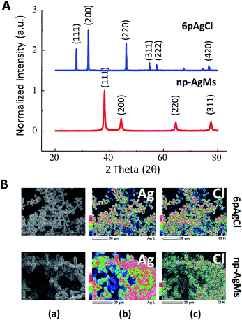 | ||
| Fig. 2 (A) XRD pattern of particle before (6pAgCl) and after (np-AgMs) galvanic replacement. (B) EDS mapping of 6pAgCl and np-AgMs with (a) original SEM images, (b) composition of Ag and (c) composition of Cl. The EDS spectra including the percentage of each element are shown in ESI Fig. S2.† | ||
As the fabricated np-AgMs exist as particles with a clean surface without any surface capping agents, they present an interesting case for use as a SERS substrate, which is predominantly a surface phenomenon to enhance the Raman signal. The interconnected pores with nano-size which spread all over the particle, can act as the host hotspot containing a high electric field.7,20 These hotspots are expected to cause significant SERS enhancement. Interestingly, np-AgMs with a porous structure can be employed as one single particle acting as a reproducible SERS substrate. This can be performed under normal confocal Raman spectroscopy conditions for sensing and also imaging applications. As the particle size is in the microscale, the focusing of the laser on the particle is quite simple and accurate. Furthermore, the volume of the analyte required for detection of an isolated particle is very small, in the order of sub-microliters. A drop volume of 1 uL water was used to demonstrate the particles in an injected solution under a microscope (ESI† Fig. S3). Just 1 μL can cover several np-AgMs particles and not induce aggregation of those particles. It is noted that there is no requirement to pour the solution around several np-AgMs because only a single np-AgM can be used as a SERS substrate. Therefore, the analyte volume can be dramatically reduced and minimized in the range of nanoliters using advanced injection methods such as a carbon nanotube injection tip.27
The SERS enhancement efficiency of np-AgMs was investigated using p-aminothiophenol (PATP) as a probe molecule. PATP was chosen as an analyte because it is a non-resonance molecule and easily chemisorbs on the Ag surface through formation of Ag–S covalent bonds.31 Therefore, the SERS signal is very sensitive to the substrate material, making it a good probe molecule for identifying the electronic properties of the SERS substrates. As discussed above, our np-AgMs contain six pods generated from the same particle center. The six tips on a np-AgMs particle might be cracked by the mechanical force or sonication into several patterns, as shown in ESI† Fig. S4. However, np-AgMs with tips oriented in a square planar geometry were selected for use as the SERS substrate as these contain the maximum tips with a parallel plane.
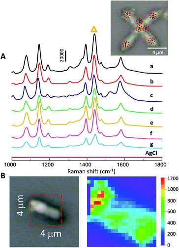
SERS spectra collected from np-AgMs at seven different places, exposed to 10 μM of PATP with subsequent excitation with a green laser (514.5 nm wavelength) are shown in Fig. 3A. The figure inset shows the seven detection positions. The relative standard deviation (RSD) of a major SERS peak at 1439 cm−1 (labeled with triangle symbol) was calculated to estimate the repeatability of SERS signal. In this case, an RSD value of only 0.11 was obtained. This reveals a good reproducibility across all positions of single np-AgMs.
It appears that the junction and the centre of a square planar np-AgM create a good situation to obtain the maximum electromagnetic field intensity of the PATP molecules adsorbed near the centre, while there is a small variation of SERS detection on the different pods. This suggests that SERS activity might originate from around the particle, especially at the centre and junction compared with the tip parts. Near field images of the electromagnetic field using PLANC-FDTD (Information and Mathematical Science Laboratory Inc., Ver. 6.2) software were calculated as shown in ESI Fig. S5.† In the FDTD calculation, the designed particle was generated with dimension length and shape similar to the particles observed from SEM images. The mesh sizes were set to 50 nm inside and outside a silver microstructure. The calculated electric fields generated around the particle support the conclusion that SERS enhancement is high at the junction and the centre of a square planar particle, while lower SERS enhancement is observed on the pods. In addition, a control test was performed using a 6pAgCl particle, but no Raman signal was detected.
In our study, Raman mapping was used to represent the enhancement activity of the particle. To test the enhancement activity, the SERS signal on the individual tip of the particle was collected on a square of 4 × 4 μm2 with a total of 400 scan points (i.e. 20 × 20 scans with equal interval at 200 × 200 nm2). To avoid the intensity cut-off, only 1 μM of PATP was exposed with an exposure time of only 2 seconds/point in the mapping measurements. This chosen area includes both the particle and an empty area in order to obtain the contrast mapping images. The intense peak at 1439 cm−1 was selected for visualization on the map as it is a dominant peak in the Raman spectra. The enhancement activity was clearly observed on the individual particle, while there were no observed Raman signals on other parts. Moreover, the homogenous distribution of the Raman intensity of a main peak strongly supports the notion that the porous portion on the np-AgMs pod is uniform over a large area and capable of generating a SERS signal with very high enhancement.
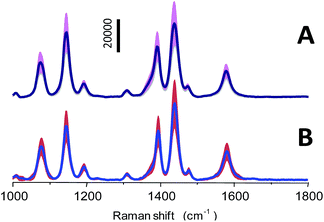
However, the reproducibility of Raman signals from the SERS substrate is a crucial factor for SERS-based quantitative applications. To test the reproducibility, SERS spectra of PATP with a concentration of 10 μM from 50 different particles and three independent batches (10 particles/batch) of the np-AgMs were collected under identical Raman conditions. Average SERS spectra plus/minus the intensity standard deviation are shown in Fig. 4. Using the 1439 cm−1 peak as the reference peak, the RSD value of signal intensities of this major peak is observed ∼0.25 in both cases. It should be noted that the variations in the different particles/batches such as the focusing plane, position, size and shape of the detected particle have an obvious effect on the RSD value of signal intensities. Therefore, the RSD value from the different particles/batches is higher than the RSD value obtained from the same particles. However, the spectrum pattern and intensity ratio of peaks are highly consistent, revealing satisfactory reproducibility.
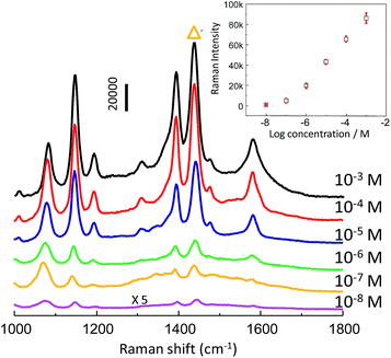
After the enhancement activity and detection reproducibility were evaluated, the SERS intensity as a function of analyte concentration was investigated. Serial dilutions of PATP were prepared in a range of 10−8–10−3 M. The np-AgMs substrate demonstrated that the SERS enhancement for PATP can be observed at concentrations as low as 10−8 M (Fig. 5). The inset of Fig. 5 shows concentration-dependent SERS intensities. A strong SERS band at 1439 cm−1 with the highest intensity was chosen as the intensity standard. Error bars indicate the standard deviation in the SERS intensities calculated from five measured repetitions (randomly selected particles and positions). It can be seen from the inset that a good linear relationship of SERS intensities with small standard deviation (error bar) over the large range of PATP concentration (10−7–10−3 M) exists. This demonstrates that the substrate is appropriate for the relatively quantitative detection of an analyte that can be absorbed on the np-AgMs surface.
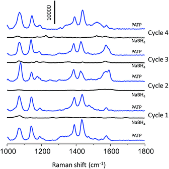
The SERS reusability of the np-AgMs particle was examined. To express this, a np-AgMs substrate was first immersed in a solution containing PATP, then the SERS signals were measured and finally the np-AgMs particles were washed with a NaBH4 aqueous solution (0.5 M) for 5 min. The ultimate aim using NaBH4 was to clean the surface of the substrate to realize reproducibility for the repeated uses, as PATP on np-AgMs can be rapidly and completely removed by NaBH4 treatment.34,35 The substrate was then washed with water to remove the residual ions and analyte molecules, followed by ethanol, and dried in air. Fig. 6 shows the results of the analyte collected on initial SERS detection and after washing several times (four times). The spectra for 1 μM of PATP on the substrate before and after cleaning with NaBH4 solution were collected. The signals of PATP disappeared completely after the first cleaning. Upon repeating the cycle four times, the peak patterns of PATP on the cleaned substrate were similar to those of a new substrate. This alternating SERS analysis shows that the np-AgMs is a feasible recyclable SERS substrate.
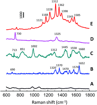
The proposed SERS substrate with the advantages of rapidness, high sensitivity and reusability is compatible with high-throughput analytical methods. Development of rapid and cost-effective methods for biomedical research has attracted considerable attention in recent years. In the present study, the use of np-AgMs for SERS detection of various biomolecules including deoxyribonucleic acid, hemoprotein (catalase, cytochrome C) and protein with no chromophore (lysozyme) is demonstrated. SERS spectra obtained from the molecules at a concentration of 500 μg mL−1 are depicted in Fig. 7. The SERS measurements of the molecules were carried out using a constant laser power of 1 mW with different exposure times. The SERS spectrum of catalase shows typical vibration modes of υ10, υ2, and υ4 at 1652 cm−1, 1574 cm−1, and 1370 cm−1, respectively. These vibration modes are assigned as the skeletal bands of the porphyrin structure in catalase.36 For lysozyme, an amide I (1660 cm−1) band of the α-helix structure and bands of the aromatic residues of Phe (1002 cm−1) and Tyr (851 cm−1) were observed.36 The deoxyribonucleic acid exhibits two major bands from the ring-breathing mode of adenine at 730 cm−1 and the mixed in-plane stretching motions of the adenine ring at 1325 cm−1.27 Raman bands of typical vibration modes of cytochrome C at υ22A2g (1121 cm−1), υ30B2g (1168 cm−1), υ13B1g (1224 cm−1), υ21A2g (1312 cm−1), and υ11B1g (1543 cm−1) are clearly observed.37 Moreover, a np-AgMs control test set with phosphate buffer was also performed (Fig. 7 spectrum A), but no interference Raman signal was detected. It should be noted that the SERS signal of hemoprotein (cytochrome C) is much more sensitive than the other biomolecules and it requires a very short exposure time. Cytochrome C gives a strong SERS signal because it has a heme chromophore which is a Raman dye. The ability to detect various kinds of biomolecules, such as hemoprotein, protein without chromophore and DNA strains, presents an interesting prospect for using the substrates for direct, inexpensive and label-free detection.
4. Conclusions
Nanoporous silver microstructures were successfully fabricated from hexapod AgCl microstructures. The galvanic replacement reaction did not alter the structural envelope of the microstructures. The micrometer size structures enable ease handling to perform position-dependent SERS spectral acquisition without any aggregation process. Only 1 μL of sub-micro molar concentration was required for detection. The nanoporous structure provides highly enhanced Raman signal with exceptional stability. There were no significant SERS signal changes after four times chemical regenerations. The highly stable structure with strong Raman enhancement might be used in a micro-fluidic flow cell. As the fabrication process did not involve usage of either capping agent or stabilizers, the clean silver surface enabled rapid and easy functionalization. Label-free SERS acquisition of important biomolecules including hemoprotein, protein without chromophore, and DNA strain was demonstrated with concentrations of analytes as low as 500 μg mL−1.Acknowledgements
This research was supported by the Ratchadaphiseksomphot Endowment Fund 2013 of Chulalongkorn University (CU-56-602-AM). Sanpon Vantasin would like to thank the Yoshida Scholarship Foundation for the scholarship support. Dr Rick Attrill, a lecturer at the Department of Chemistry, Faculty of Science, Chulalongkorn University is also acknowledged for English corrections and suggestions.Notes and references
- S. Link, M. B. Mohamed and M. A. El-Sayed, J. Phys. Chem. B, 1999, 103, 3073 CrossRef CAS.
- P. L. Stiles, J. A. Dieringer, N. C. Shah and R. P. Van Duyne, Annu. Rev. Phys. Chem., 2008, 1, 601 CrossRef CAS PubMed.
- S. Song, Y. Qin, Y. He, Q. Huang, C. Fan and H. Y. Chen, Chem. Soc. Rev., 2010, 39, 4234 RSC.
- J. Kneipp, H. Kneipp and K. Kneipp, Chem. Soc. Rev., 2008, 37, 1052 RSC.
- K. S. Krishna, C. S. S. Sandeep, R. Philip and M. Eswaramoorthy, ACS Nano, 2010, 4, 2681 CrossRef CAS PubMed.
- Y. Kitahama, A. Enogaki, Y. Tanaka, T. Itoh and Y. Ozaki, J. Phys. Chem. C, 2013, 117, 9397 CAS.
- B. Gilbert, R. K. Ono, K. A. Ching and C. S. Kim, J. Colloid Interface Sci., 2009, 339, 285 CrossRef CAS PubMed.
- D. A. Clayton, T. E. Mcpherson, S. Pan, M. Chen, D. A. Dixon and D. Hu, Phys. Chem. Chem. Phys., 2013, 15, 850 RSC.
- P. Aldeanueva-Potel, E. Carbo-Argibay, N. Pazos-Perez, S. Barbosa, I. Pastoriza-Santos, R. A. Alvarez-Puebla and L. M. Liz-Marzan, ChemPhysChem, 2012, 13, 2561 CrossRef CAS PubMed.
- M. Fan, G. F. S. Andrade and A. G. Brolo, Anal. Chim. Acta, 2011, 693, 7 CrossRef CAS PubMed.
- Y. Li, N. Koshizaki, H. Wang and Y. Shimizu, ACS Nano, 2011, 5, 9403 CrossRef CAS PubMed.
- G. Liu, W. Cai, L. Kong, G. Duan, Y. Li, J. Wang and Z. Cheng, J. Hazard. Mater., 2013, 248, 435 CrossRef PubMed.
- G. Liu, X. Li, W. Wang, F. Zhou, G. Duan, Y. Li, Z. Xu and W. Cai, Small, 2014, 10, 2374 CrossRef CAS PubMed.
- K. G. Stamplecoskie and J. C. Scaiano, J. Phys. Chem. C, 2011, 115, 1403 CAS.
- S. L. Kleinman, R. R. Frontiera, A. I. Henry, J. A. Dieringer and R. P. Van-Duyne, Phys. Chem. Chem. Phys., 2013, 15, 21 RSC.
- M. Rycenga, C. M. Cobley, J. Zeng, W. Li, C. H. Moran, Q. Zhang, D. Qin and Y. Xia, Chem. Rev., 2011, 111, 3669 CrossRef CAS PubMed.
- Y. Kitahama, M. Kashihara, T. Itoh and Y. Ozaki, J. Phys. Chem. C, 2013, 117, 2460 CAS.
- Y. Ding and M. Chen, MRS Bull., 2009, 34, 569 CrossRef CAS.
- S. Polarz and B. Smarsly, J. Nanosci. Nanotechnol., 2002, 2, 581 CrossRef CAS PubMed.
- Q. Liu, X. Jiang, S. Gao, H. Xu and L. Sun, Mater. Lett., 2014, 128, 322 CrossRef CAS PubMed.
- H. Qiu, Z. Zhang, X. Huang and Y. Qu, ChemPhysChem, 2011, 12, 2118 CrossRef CAS PubMed.
- P. Nielson, S. Hassing, O. Albrektsen, S. Foghmoes and P. Morgan, J. Phys. Chem. C, 2009, 113, 14165 Search PubMed.
- S. L. Kleinman, R. R. Frontiera, A. I. Henry, J. A. Dieringer and R. P. Van Duyne, Phys. Chem. Chem. Phys., 2013, 15, 21 RSC.
- A. Gutes, C. Carraro and R. Maboudian, JACS comm., 2010, 132, 1476 CrossRef CAS PubMed.
- L. Zeiri, K. Rechav, Z. Porat and Y. Zeiri, Appl. Spectrosc., 2012, 66, 294 CrossRef CAS PubMed.
- R. Li, X. J. Liu, H. Wang, Y. Xu, X. M. Chu and Z. P. Lu, Corros. Sci., 2014, 84, 159–164 CrossRef CAS PubMed.
- G. Mettela, S. Siddhanta, C. Narayana and G. U. Kulkarni, Nanoscale, 2014, 6, 7480 RSC.
- H. Gatemala, C. Thammacharoen and S. Ekgasit, CrystEngComm, 2014, 16, 6688 RSC.
- I. Maudos, J. M. Chimenos, M. Segarra and F. Espiell, Hydrometallurgy, 1996, 40, 153 CrossRef CAS.
- W. Zhang, J. Yang and X. Lu, ACS Nano, 2012, 6, 7397 CrossRef CAS PubMed.
- C. Xu, Y. Li, F. Tain and Y. Ding, ChemPhysChem, 2010, 11, 3320 CrossRef CAS PubMed.
- L. Yang, M. Qi and M. Jin, CrystEngComm, 2013, 15, 2804 RSC.
- Y. Wang, W. Ji, Z. Yu, R. Li, X. Wang, W. Song, W. Ruan, B. Zhao and Y. Ozaki, Phys. Chem. Chem. Phys., 2014, 16, 3153 RSC.
- S. M. Ansar, F. S. Ameer, W. Hu, S. Zou, C. U. Pittman Jr and Z. Dongmao, Nano Lett., 2013, 13, 1226 CrossRef CAS PubMed.
- C. X. Zhang, L. Liu, H. J. Yin, H. Fang, Y. M. Zhao, C. J. Bi and H. J. Xu, Appl. Phys. Lett., 2014, 105, 011905 CrossRef PubMed.
- X. X. Han, G. G. Hunag, B. Zhao and Y. Ozaki, Anal. Chem., 2009, 81, 3329 CrossRef CAS PubMed.
- M. L. Donten, A. Krolikowska and J. Bukowska, Phys. Chem. Chem. Phys., 2009, 11, 3390 RSC.
Footnote |
| † Electronic supplementary information (ESI) available: SEM images with low and high magnification including the grain size distribution of a nanoporous Ag microstructure (np-AgMs) by galvanic replacement using Zn plate and NaCl solution at various concentrations, EDS spectra of hexapod AgCl microstructure (6pAgCl) and nanoporous Ag microstructure (np-AgMs), optical microscopic images of np-AgMs using low and high magnification of the solution surrounding the isolated particles, The possible patterns of the particles isolated from the hexapod np-AgMs found under the optical microscope, designed particles including the determined plane waves used in FDTD calculations and excited near-field images of an electromagnetic field on the hexapod silver microstructure by FDTD calculations. See DOI: 10.1039/c4ra11890a |
| This journal is © The Royal Society of Chemistry 2015 |

