Simultaneously enabling dynamic transparency control and electrical energy storage via electrochromism†
Haizeng
Li
 * and
Abdulhakem Y.
Elezzabi
Ultrafast Optics and Nanophotonics Laboratory, Department of Electrical and Computer Engineering, University of Alberta, Edmonton, Alberta T6G 2V4, Canada. E-mail: haizeng@ualberta.ca
First published on 2nd January 2020
Abstract
Transparency-switchable electrochromic devices (ECDs) offer promising applications, including variable optical attenuators, optical shutters, optical filters, and smart windows for energy-efficient buildings. However, the operation of conventional ECDs requires external voltages to trigger coloration/de-coloration processes, which makes them far from being an optimal energy-efficient technology. Electrochromic batteries that incorporate electro-optical modulation and electrical energy storage functionalities in a single platform, are highly-promising in the realization of energy-efficient ECDs. Herein, we report a novel Zn–Prussian blue (PB) system for aqueous electrochromic batteries. By utilizing different dual-ion electrolytes with various cations (e.g. Zn2+–K+ and Zn2+–Al3+), the Zn–PB electrochromic batteries demonstrate excellent performance. We show that the K+–Zn2+ dual-ion electrolyte in the Zn–PB configuration endows a rapid self-bleaching time (2.8 s), a high optical contrast (83% at 632.8 nm), and fast switching times (8.4 s/3 s for the bleaching/coloration processes). Remarkably, the aqueous electrochromic battery exhibits a compelling energy retrieval of 35.7 mW h m−2, where only 47.5 mW h m−2 is consumed during the round-trip coloration–bleaching process. These findings may open a new direction for developing advanced net-zero energy-consumption ECDs.
New conceptsThe newly-born electrochromic battery operates in an opposite fashion to a traditional electrochromic device, which facilitates the ability to efficiently retrieve the consumed energy. The basic architecture of this class of electrochromic devices warrants further investigation, in particular, the selection of an appropriate electrochromic material for an electrochromic device with efficient energy retrieval functions. Here, we demonstrated the first aqueous Zn–PB electrochromic device, which achieves a high optical contrast as well as a compelling energy retrieval functionality. Such a high-performance electrochromic device endows the possibility of the development of net-zero energy-consumption electrochromic devices. |
Electrochromic devices (ECDs) have attracted attention due to their ability to dynamically control optical transmittance and are widely used in optical shutters, displays, optical filters, and smart windows.1–7 Nonetheless, electrical energy is required to operate the ECDs,8 as such, the inherent energy consumption can curtail their energy-efficient features. In this regard, researchers have been striving to develop electrochromic capacitive devices to recycle the consumed electrical energy back. However, electrochromic capacitive devices can recycle only a small amount of the consumed energy via the slow spontaneous ion de-intercalation process.9–11 Nonetheless, for these devices, an applied voltage is still needed to accelerate the ion de-intercalation process.12,13 Moreover, these devices bring an incompatibility between dynamic transparency control and electrical energy storage.14 To date, it has been a great challenge to develop efficient ECDs that perfectly incorporated electro-optical modulation and electrical energy storage functionalities.
Recently, we demonstrated an inverse ECD platform, namely an aqueous electrochromic battery, that satisfies the requirements of the dynamic transparency control and electrical energy storage functionalities.15–17 Certainly, the basic architecture of this class of electrochromic devices warrants further investigation, in particular, the efficient electrical energy storage functionality.
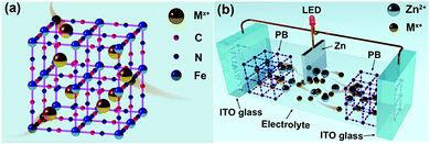
Similar to the requirement of electrochromic materials having open-framework structures for conventional high electro-optical modulation ECDs with fast switching times.18–20 The electrochromic materials also play an important role in the electrochromic battery platform. Materials having an open-framework structure, such as PB (represented as KFeFe(CN)6) and its analogs, have been extensively used in electrochromic devices and batteries.21–23 The open-framework structure of the PB lattice is similar to the perovskite-like (ABO3) structure having large interstitial A-sites (3.2 Å).24 Such a lattice structure facilitates rapid insertion of a variety of cations (e.g. Li+, Zn2+, K+, Al3+, Na+ and their corresponding hydrated ions) from aqueous solutions (Fig. 1(a)). Consequently, PB is expected to be an ideal cathode material for aqueous electrochromic batteries. However, the question of which cation is more suitable for high-performance PB-based aqueous electrochromic batteries is still unanswered.
Herein, we present a novel Zn–PB electrochromic battery system having excellent compatibility between dynamic transparency control and electrical energy storage. The utilization of a 1 M ZnSO4–KCl dual-ion electrolyte results in a significantly enhanced performance of the Zn–PB electrochromic batteries. The Zn2+/K+ Zn–PB electrochromic battery exhibits a high optical contrast (ΔT, 83% at 632.8 nm), a rapid self-bleaching time (2.8 s) and fast switching times (8.4 s/3 s for the bleaching/coloration processes). Remarkably, the Zn2+/K+ dual-ion Zn–PB electrochromic battery exhibits a compelling energy retrieval of 35.7 mW h m−2, where only 47.5 mW h m−2 is consumed during the round-trip coloration–bleaching processes. For a proof of concept, a large area (10 cm × 8 cm) Zn2+/K+ dual-ion Zn–PB electrochromic battery prototype was assembled (Fig. 1(b)). The device exhibits a high ΔT of 78.6%, fast switching times (16 s/18 s for the bleaching/coloration processes), and a high energy retrieval of 48 mW h m−2.
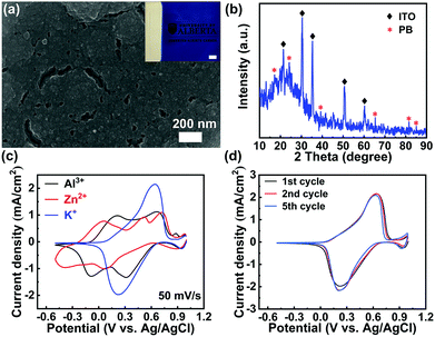
The PB films were electrodeposited on indium tin oxide (ITO) glass substrates by the well-established Neff method (see the Experimental section in the ESI†).25 Scanning Electron Microscopy (SEM) image analysis shows that the as-prepared film is compact (Fig. 2(a)), which is similar to the previously reported PB films.24 The weak asterisk peaks, shown in the X-ray diffraction (XRD) pattern (Fig. 2(b)), correspond to the plane-reflections of the Fe4(Fe(CN)6)3 phase (Joint Committee on Powder Diffraction Standards No. 01-0239).24 The Fourier transform infrared spectroscopy (FTIR) spectrum presented in Fig. S1 (ESI†) further confirms the successful deposition of the PB film on ITO glass via the well-established Neff method. To investigate a suitable aqueous electrolyte system for high-performance PB-based electrochromic batteries, K+, Zn2+, and Al3+ were explored for comparison. These ions represent typical cases of monovalent, divalent, and trivalent cations, respectively. Fig. 2(c) depicts the first cyclic voltammetry (CV) scan of the PB film in 1 M KCl, 1 M ZnSO4, and 1 M AlCl3, respectively. The corresponding reduction and oxidation peak potentials, observed from the CV curves, are summarized in Table S1 in the ESI.† The average redox potential decreases as the radius of the hydrated ion (Al3+ < K+ < Zn2+) increases, which is in good agreement with previous reports.26 The multiple cathodic and anodic peaks suggest the presence of multiple redox reactions during multivalent ion (Zn2+ and Al3+) insertion. As indicated in Fig. 2(c), the Zn2+ intercalation/de-intercalation process is less effective, compared to the Al3+ and K+. The CV curve of the PB film in 1 M ZnSO4 displays broad and multi-redox peaks with a drastic depreciation in current densities during successive cycling (Fig. S2(a) in the ESI†). The multi-redox peaks are attributed to the multiple processes of Zn2+ and Al3+ intercalation/de-intercalation, including the reduction/oxidation reactions of low-spin FeII/FeIII and high-spin FeII/FeIII coupling to C and N atoms, respectively.27 The multivalent cations (Zn2+, Al3+) may lead to a large lattice distortion, due to the strong electrostatic interactions, which results in redox peak shift during successive cycling (Fig. S2 in the ESI†). In contrast, only one pair of well-defined redox peaks was observed in 1 M KCl. This pair represents the reduction/oxidation processes of low-spin FeII/FeIII coupling to C atoms via the insertion/deintercalation of K+.28 Notably, the redox peaks of the PB film in 1 M KCl remain almost unchanged during cycling (Fig. 2(d)), suggesting a highly reversible redox reaction.
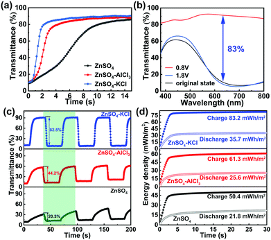
The above redox performance in different electrolytes reveals that the electrodeposited PB film is an inappropriate cathode material for Zn2+. However, Zn2+ is mandatory for the striping/plating of the Zn anode in the Zn–PB electrochromic batteries. Therefore, the utilization of an aqueous dual-ion electrolyte in the Zn–PB electrochromic battery system is considered to be an ideal strategy to fully exploit the advantages of a Zn anode and a PB cathode. To find an optimum dual-ion electrolyte for the demonstration of real-world applications, pure Zn2+ electrolyte, K+/Zn2+, and Al3+/Zn2+ dual-ion electrolytes were investigated in half-cell configurations for comparison (see detailed information of the electrolytes in the ESI†). Similar to our previous work,15 the redox potential difference (ΔE) between the Zn anode and the PB cathode serves as a driving force to cause the oxidation of Zn and reduction of PB. Thus, in this spontaneous thermodynamic downhill process, the PB cathode can be self-bleached when the Zn anode and PB cathode are connected together. The self-bleaching behavior of the PB cathode in the different electrolytes is shown in Fig. 3(a). Here, the PB cathode exhibits the fastest self-bleaching behavior in 1 M ZnSO4–KCl. The self-bleaching time (defined as the time required for the transmittance to change by 90% of the maximum optical contrast) is measured to be 2.8 s in 1 M ZnSO4–KCl, while the self-bleaching times are measured to be 4.5 s and 9.7 s in 1 M ZnSO4–AlCl3 and 1 M ZnSO4, respectively. The 2.8 s self-bleaching time is the fastest spontaneous bleaching/coloration time reported to date.15,29–31 The CV and ex situ X-ray photoelectron spectroscopy (XPS) analyses (Fig. S3 in the ESI†), support the conclusion that the different self-bleaching behaviors are attributed to the intercalation of different ions.
Fig. 3(b) depicts the change (ΔT) of the PB cathode configured with a Zn foil in a cuvette filled with 1 M ZnSO4–KCl. The PB cathode is colored when it is charged at 1.8 V, while it is bleached when discharged at 0.8 V. The original state transmittance is 10.6% at 632.8 nm (black curve in Fig. 3(b)), which is similar to the charged state (1.8 V) transmittance (8.4% at 632.8 nm, blue curve). This indicates that the charged/colored state is stable (in good agreement with the bistability results shown in Fig. S6, ESI†). The discharged state (0.8 V) transmittance is measured to be 91.3% at 632.8 nm. As such, the difference in the transmittance at the bleached and original states is 80.7%. The ΔT of the PB cathode, defined as the transmittance difference between the charged and discharged states, is calculated to be 83% at 632.8 nm (without subtracting the transmittance loss of an ITO/glass substrate). The ΔT is higher than the ones obtained when using 1 M ZnSO4–AlCl3 and 1 M ZnSO4 electrolytes (Fig. S4 in the ESI†). Notably, this ΔT is also higher than previously reported values.13,32–34 The switching times of a PB cathode in different electrolytes are shown in Fig. 3(c). The bleaching time (tb) and coloration time (tc), in 1 M ZnSO4–KCl, are measured to be 8.4 s and 3 s, respectively. The bleaching time of 8.4 s, slower than the self-bleaching time (2.8 s), is attributed to lower voltage bias during the self-bleaching process. The voltage is 0 V during the self-bleaching process, while the voltage is 0.8 V during the bleaching process. This low self-bleaching voltage accelerates the ion-intercalation process, thus resulting in a shorter switching time. The switching times, especially tb, are faster than those obtained from 1 M ZnSO4–AlCl3 (tb/tc = 11/2.5 s) and 1 M ZnSO4 (tb/tc = 23.6/3.4 s). The high ΔT and fast switching times make the Zn2+/K+ dual-ion Zn–PB electrochromic battery system a highly promising platform in comparison with the previously reported electrochromic batteries (see detailed comparisons in Table S2 in the ESI†). Along with the high ΔT and fast switching times shown in the Zn2+/K+ dual-ion Zn–PB electrochromic battery system, the coloration efficiency (CE) in such a hybrid system is calculated to be 138 cm2 C−1 (Fig. S5(a) in the ESI†). The CE value is higher than that measured in 1 M ZnSO4–AlCl3 (105.5 cm2 C−1, Fig. S5(b), ESI†) and 1 M ZnSO4 (84.9 cm2 C−1, Fig. S5(c), ESI†), indicating that K+ is efficient for PB cathodes. In addition, the Zn2+/K+ dual-ion Zn–PB electrochromic battery exhibits an excellent memory effect in its colored state and a remarkable self-rechargeability when bleached (Fig. S6 in the ESI†). Notably, the newly-enabled function of the Zn–PB electrochromic battery, compared to a conventional electrochromic device, is the ability to partially retrieve the consumed energy expended during coloration. An important metric that characterizes an electrochromic battery performance is the round-trip net-energy consumption. As shown in Fig. 3(d), the Zn2+/K+ dual-ion Zn–PB electrochromic battery recovers 35.7 mW h m−2 from 83.2 mW h m−2. The round-trip net-energy consumption of the Zn2+/K+ dual-ion Zn–PB electrochromic battery is 47.5 mW h m−2, which is slightly higher than the ones of the Zn–PB electrochromic batteries utilizing 1 M ZnSO4–AlCl3 (35.7 mW h m−2) and 1 M ZnSO4 (28.6 mW h m−2) electrolytes. The higher net-energy consumption is attributed to the high capacity achieved in 1 M ZnSO4–KCl (Fig. S7 in the ESI†). Even though the round-trip net-energy consumption in 1 M ZnSO4–KCl is slightly higher than that in 1 M ZnSO4–AlCl3 and 1 M ZnSO4, this electrochromic battery offers a much higher ΔT compared to others. Moreover, the Zn–PB electrochromic battery utilizing 1 M ZnSO4–KCl electrolyte exhibits improved galvanostatic cycling stability (i.e., 60% capacity retention after 300 cycles) in comparison to its performance (20% capacity retention after 300 cycles) utilizing 1 M ZnSO4–AlCl3 and 1 M ZnSO4 electrolytes (Fig. S8 in the ESI†). CV cycling measurement was conducted to investigate the stability of the Zn2+/K+ dual-ion Zn–PB electrochromic battery for extended cycles (Fig. S9 in the ESI†). Fig. S9 (ESI†) shows that the Zn2+/K+ dual-ion Zn–PB electrochromic battery retains 16% of its initial capacity and has 26.6% ΔT after 1000 CV cycles.
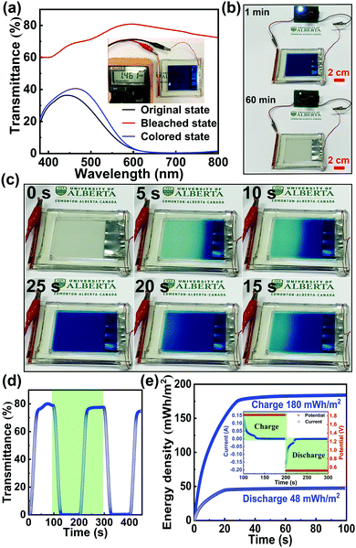
To illustrate the potential of this novel Zn2+/K+ dual-ion Zn–PB electrochromic battery for practical applications, a large-area prototype device (10 cm × 8 cm) was constructed. The schematic of the basic configuration is presented in Fig. 1(b). Here, a thin strip of Zn foil is sandwiched between two PB electrodes, and 1 M ZnSO4–KCl is used as the electrolyte. The optical transmittance spectra of the prototype device are shown in Fig. 4(a), where the as-assembled device is nearly opaque at 632.8 nm (∼1% transmittance), due to the utilization of the two PB cathodes. Interestingly, during the self-bleaching process (Fig. 4(b) and Fig. S10 in the ESI†), the as-assembled device supplies a voltage (OCV) of ∼1.46 V which is capable of lighting an LED (0.5 V regulated) for more than 60 minutes. Such a feature demonstrates the energy retrieval functionalities of this class of electrochromic devices. The device's bleached state transmittance is measured to be ∼79.6% at 632.8 nm (the red curve in Fig. 4(a)), as such, the measured ΔT = 78.6% is the highest ever reported for an electrochromic device.35–39 The bleached state transmittance (∼79.6%) of the prototype device is less than that of the single PB electrode (∼91.3%, Fig. 3(b)). This is attributed to the additional transmittance loss of the second PB electrode. Accordingly, owing to the synergistic coloration effect of the two PB electrodes in the prototype device, the device's colored state transmittance (∼1% at 632.8 nm) is lower than that of a single PB cathode (∼8%, Fig. 3(b)). The self-bleached device can be quickly charged/colored via applying an external voltage of 1.8 V. Fig. 4(c) shows the coloration/charging process of the self-bleached device. The transmittance of the device can be easily recovered to its original value of 1% at 632.8 nm in only 25 s (the blue curve in Fig. 4(a)). This is accompanied by an enhancement of the OCV to 1.77 V (Fig. S11 in the ESI†). The dynamic transmittance at 632.8 nm, shown in Fig. 4(d), further confirms the fast kinetics of the prototype device. The switching times are measured to be 18 s for coloration/charging and 16 s for bleaching/discharging. The slight increase in the switching times compared to that of a single PB electrode (Fig. 3(c)) is attributed to the higher electrode resistance of the large prototype device. The retrieved energy is calculated to be 48 mW h m−2 for the prototype device (Fig. 4(e)), and the round-trip consumed energy is 132 mW h m−2. This round-trip consumed energy is higher than that of the PB cathode tested in a cuvette via a two-electrode configuration (47.5 mW h m−2), which is also attributed to the high electrode resistance in large-area PB cathodes.
Conclusions
In summary, a novel Zn–PB electrochromic device, with a Zn2+/K+ dual-ion electrolyte, has been demonstrated for the first time. The device possesses a high energy retrieval capability which offers promising functionalities in reducing the ECD energy consumption. This class of electrochromic devices eliminates the requirement of an external voltage to trigger the bleaching process, while they partially retrieve the consumed energy for coloration. The reported Zn2+/K+ dual-ion Zn–PB electrochromic device exhibits a rapid self-bleaching time (2.8 s), fast switching times (3 s/8.4 s for coloration/bleaching state), and a high optical contrast (83%). These key properties mark a significant improvement over previously reported electrochromic devices, making the Zn2+/K+ dual-ion Zn–PB electrochromic device the most promising candidate for switchable optical filters, electrochromic tunable micro-optics, transparent displays, and electrochromic smart windows.Conflicts of interest
There are no conflicts to declare.Acknowledgements
This work was supported by the Natural Sciences and Engineering Research Council of Canada (Grant File No. CRDPJ 509210-17), Alberta Innovates, and All Weather Windows Ltd. The authors are grateful to Weilon Chang for the schematic illustrations.Notes and references
- F. H. Wang, M. E. Itkis, E. Bekyarova and R. C. Haddon, Nat. Photonics, 2013, 7, 460–466 Search PubMed.
- S. M. Islam, T. S. Hernandez, M. D. McGehee and C. Barile, Nat. Energy, 2019, 4, 223–229 CrossRef CAS.
- W. Zhang, X. Wang, Y. Wang, G. Yang, C. Gu, W. Zheng, Y. M. Zhang, M. Li and S. X. Zhang, Nat. Commun., 2019, 10, 1559 CrossRef PubMed.
- G. W. Kim, Y. C. Kim, I. J. Ko, J. H. Park, H. W. Bae, R. Lampande and J. H. Kwon, Adv. Opt. Mater., 2018, 6, 1701382 CrossRef.
- A. Hein, C. Kortz and E. Oesterschulze, Sci. Rep., 2019, 9, 15822 CrossRef PubMed.
- Y. Li, J. van de Groep, A. A. Talin and M. L. Brongersma, Nano Lett., 2019, 19, 7988–7995 CrossRef CAS PubMed.
- H. N. Kim and S. Yang, Adv. Funct. Mater., 2019 DOI:10.1002/adfm.201902597.
- S. Q. Zhao, Y. H. Liu, Z. Ming, C. Chen, W. W. Xu, L. Chen and W. Huang, Opt. Express, 2019, 27, 29547–29557 CrossRef PubMed.
- S. Cao, S. L. Zhang, T. R. Zhang, Q. F. Yao and J. Y. Lee, Joule, 2019, 3, 1152–1162 CrossRef CAS.
- H. Z. Li, L. McRae, C. J. Firby, M. Al-Hussein and A. Y. Elezzabi, Nano Energy, 2018, 47, 130–139 CrossRef CAS.
- H. Z. Li, J. M. Li, C. Y. Hou, D. Ho, Q. H. Zhang, Y. G. Li and H. Z. Wang, Adv. Mater. Technol., 2017, 2, 1700047 CrossRef.
- Y. Kim, M. Han, J. Kim and E. Kim, Energy Environ. Sci., 2018, 11, 2124–2133 RSC.
- T. G. Yun, M. Park, D. H. Kim, D. Kim, J. Y. Cheong, J. G. Bae, S. M. Han and I. D. Kim, ACS Nano, 2019, 13, 3141–3150 CrossRef CAS PubMed.
- P. H. Yang, P. Sun and W. J. Mai, Mater. Today, 2016, 19, 394–402 CrossRef CAS.
- H. Li, L. McRae, C. J. Firby and A. Y. Elezzabi, Adv. Mater., 2019, 31, e1807065 CrossRef PubMed.
- H. Z. Li, C. J. Firby and A. Y. Elezzabi, Joule, 2019, 3, 2268–2278 CrossRef CAS.
- W. Zhang, H. Li, M. Al-Hussein and A. Y. Elezzabi, Adv. Opt. Mater., 2019 DOI:10.1002/adom.201901224.
- G. W. Kim, R. Lampande, D. C. Choe, I. J. Ko, J. H. Park, R. Pode and J. H. Kwon, Opt. Express, 2018, 26, 8493–8502 CrossRef CAS PubMed.
- S. Zhang, S. Cao, T. Zhang, Q. Yao, H. Lin, A. Fisher and J. Y. Lee, Small Methods, 2019 DOI:10.1002/smtd.201900545.
- A. Agrawal, I. Kriegel, E. L. Runnerstrom, F. Scotognella, A. Llordes and D. J. Milliron, ACS Photonics, 2018, 5, 2044–2050 CrossRef CAS.
- J. Liu, W. Zhou, S. Walheim, Z. Wang, P. Lindemann, S. Heissler, J. Liu, P. G. Weidler, T. Schimmel, C. Woll and E. Redel, Opt. Express, 2015, 23, 13725–13733 CrossRef CAS PubMed.
- B. Wang, Y. Han, X. Wang, N. Bahlawane, H. Pan, M. Yan and Y. Jiang, iScience, 2018, 3, 110–133 CrossRef CAS PubMed.
- Y. Yue, H. Li, K. Li, J. Wang, H. Wang, Q. Zhang, Y. Li and P. Chen, J. Phys. Chem. Solids, 2017, 110, 284–289 CrossRef CAS.
- Z. Wang, Q. Z. Zhang, S. Cong, Z. G. Chen, J. X. Zhao, M. Yang, Z. H. Zheng, S. Zeng, X. W. Yang, F. X. Geng and Z. G. Zhao, Adv. Opt. Mater., 2017, 5, 1700194 CrossRef.
- V. D. Neff, J. Electrochem. Soc., 1978, 125, 886–887 CrossRef CAS.
- X. Wu, M. Shao, C. Wu, J. Qian, Y. Cao, X. Ai and H. Yang, ACS Appl. Mater. Interfaces, 2016, 8, 23706–23712 CrossRef CAS PubMed.
- Y. Lu, L. Wang, J. Cheng and J. B. Goodenough, Chem. Commun., 2012, 48, 6544–6546 RSC.
- Y. B. Chen, Z. J. Bi, X. M. Li, X. K. Xu, S. D. Zhang and X. M. Hu, Electrochim. Acta, 2017, 224, 534–540 CrossRef CAS.
- J. Wang, L. Zhang, L. Yu, Z. Jiao, H. Xie, X. W. Lou and X. W. Sun, Nat. Commun., 2014, 5, 4921 CrossRef CAS PubMed.
- J. Zhao, Y. Tian, Z. Wang, S. Cong, D. Zhou, Q. Zhang, M. Yang, W. Zhang, F. Geng and Z. Zhao, Angew. Chem., Int. Ed., 2016, 55, 7161–7165 CrossRef CAS PubMed.
- H. Zhang, Y. Yu, L. Zhang, Y. Zhai and S. Dong, Chem. Sci., 2016, 7, 6721–6727 RSC.
- W. Zhang, H. Li, C. J. Firby, M. Al-Hussein and A. Y. Elezzabi, ACS Appl. Mater. Interfaces, 2019, 11, 20378–20385 CrossRef CAS PubMed.
- P. Salles, D. Pinto, K. Hantanasirisakul, K. Maleski, C. E. Shuck and Y. Gogotsi, Adv. Funct. Mater., 2019, 29, 1809223 CrossRef.
- K.-H. Heckner and A. Kraft, Solid State Ionics, 2002, 152-153, 899–905 CrossRef CAS.
- G. F. Cai, P. Darmawan, X. Cheng and P. S. Lee, Adv. Energy Mater., 2017, 7, 1602598 CrossRef.
- W. Cheng, J. F. He, K. E. Dettelbach, N. J. J. Johnson, R. S. Sherbo and C. P. Berlinguette, Chem, 2018, 4, 821–832 CAS.
- M. Wang, X. Xing, I. F. Perepichka, Y. Shi, D. Zhou, P. Wu and H. Meng, Adv. Energy Mater., 2019, 9, 1900433 CrossRef.
- S. L. Zhang, S. Cao, T. R. Zhang, A. Fisher and J. Y. Lee, Energy Environ. Sci., 2018, 11, 2884–2892 RSC.
- S. M. Wang, Y. Kim, B. Kim, M. Han and E. Kim, Adv. Funct. Mater., 2019, 29, 1806590 CrossRef.
Footnote |
| † Electronic supplementary information (ESI) available. See DOI: 10.1039/c9nh00751b |
| This journal is © The Royal Society of Chemistry 2020 |


