 Open Access Article
Creative Commons Attribution 3.0 Unported Licence
Advances in electrode materials for Li-based rechargeable batteries
Hui Zhang
a,
Chengyu Mao
 b,
Jianlin Li
 bc and
Ruiyong Chen
 *de
*de
aQian Xuesen Laboratory of Space Technology, China Academy of Space Technology (CAST), Beijing 100094, China
bEnergy & Transportation Science Division, Oak Ridge National Laboratory, One Bethel Valley Road, P. O. Box 2008, Oak Ridge, TN 37831, USA
cBredesen Center for Interdisciplinary Research and Graduate Education, University of Tennessee, 418 Greve Hall, 821 Volunteer Blvd., Knoxville, TN 37996, USA
dKorea Institute of Science and Technology (KIST) Europe, 66123 Saarbrücken, Germany. E-mail: r.chen@kist-europe.de
eTransfercenter Sustainable Electrochemistry, Saarland University, 66125 Saarbrücken, Germany
First published on 5th July 2017
Abstract
Rechargeable lithium-ion batteries store energy as chemical energy in electrode materials during charge and can convert the chemical energy into electrical energy when needed. Tremendous attention has been paid to screen electroactive materials, to evaluate their structural integrity and cycling reversibility, and to improve the performance of electrode materials. This review discusses recent advances in performance enhancement of both anode and cathode through nanoengineering active materials and applying surface coatings, in order to effectively deal with the challenges such as large volume variation, instable interface, limited cyclability and rate capability. We also introduce and discuss briefly the diversity and new tendencies in finding alternative lithium storage materials, safe operation enabled in aqueous electrolytes, and configuring novel symmetric electrodes and lithium-based flow batteries.
1. Introduction
The commercial success of lithium-ion batteries (LIBs) since their initial invention in the 1990s has driven the technological revolution of our modern society. Broad applications, ranging from portable electronics, power tools to electric vehicles and stationary energy storage, have been achieved. Intensive technological development has been realized through the enrichment in knowledge of electrode materials, electrolyte chemistry, storage mechanisms (such as intercalation chemistry, conversion reactions, lithium storage based on cleavage/formation of covalent bonds in Li–O2 and Li–S batteries), design and fabrication of nanostructured materials and coatings.The materials chemistry related to the Li+ intercalation phenomena was first discovered in the late 1970s.1 Classic LIBs store energy by shuttling Li+ between the two electrodes through a rocking chair mechanism.2,3 Selections of electrode materials, electrolyte salts and solvents, binders, current collectors and separators have been recently reviewed by Blomgren.4 Current LIBs market is still dominated by those inorganic cathode materials (such as layered oxides, spinels and polyanion-type olivines) developed several decades ago.5 Great efforts have been devoted to reduce the cost and boost the performance of existing electrode materials. Our modern LIBs can hold more than twice as much as gravimetric energy density as those commercialized by Sony in 1991 and are ten time cheaper.6 However, the critical performance factors for LIBs such as accessible capacity, energy density, power density and service life need to be further improved to facilitate their market penetration. For instance, the driving range of electric vehicles powered by LIBs today is still unsatisfying.7
The specific capacity of electrode materials depends on the number of electrons that can be transferred per unit weight of the active materials. Numerous efforts have been made in the attempt to enhance the reversible capacity, including the development of multi-electron reaction materials,8–15 and novel battery systems such as new generations of Li–S, Li–air batteries.16 Recently, oxygen anion redox reaction has been recognized in electrode materials, leading to an increase in the reversible capacity.17 Compared to those classic insertion-type cathode and anode materials (mostly graphite-based), high capacity electrode materials are in general facing issues such as large volume change, insufficient coulombic efficiency (CE) and instable solid electrolyte interphase (SEI), leading to low rate capability, large polarization and limited cycle life.
Nanostructured electrodes have advantages such as reduced electron/Li+ diffusion length, and can improve the structural stability, and stabilize the SEI through preventing the build-up of internal stresses.18 In addition, nanosized particles also exhibit unique Li+ storage mechanisms.19–21 The present paper provides an overview for the recent developments of high capacity anode and cathode materials for Li-based rechargeable batteries through nanoengineering (Section 2), and significant performance improvement by applying nanostructured surface coatings (Section 3).
To obtain low-cost applications, safe operation and flexible systems, in Section 4, we discuss new trends in using metal-free electrode materials, novel electrolyte chemistry and new battery concepts and cell configurations for Li-based rechargeable batteries.
2. Nanostructured electrode materials
Due to the intrinsic low diffusivity of Li+ in solid state materials, the lithiation rate is seriously limited in bulky materials.22,23 In contrast, nanomaterials,24 which have reduced dimensions and thus short Li+ transportation distances, enable high reaction rates as well as fast electron transfer rates, and can boost the power of LIBs. Moreover, nanomaterials with high surface areas allow a high Li+ flux across the electrode/electrolyte interface. Modification on chemical potential for Li+ and e− for nanosized materials could also change the thermodynamics of electrode reactions and shift the electrode potential. However, nanosized materials inherit some drawbacks, such as low tap density, high reactivity towards the liquid medium during slurry preparation, and possible parasitic reactions with electrolytes.25 This section focuses on recent advances and discusses bottlenecks in the applications of nanomaterials for Li-based rechargeable batteries, organized as: (2.1) Si-based anodes; (2.2) carbon-based anodes; (2.3) lithium transition metal oxide-based cathodes; and (2.4) nanostructures in Li–S batteries.2.1 Si-based anodes
While several lithium transition metal oxide-based or polyanionic materials26 have been used as active cathode materials, graphite is the only commonly used active materials on anode side. However, graphite only allows one reversible Li+ intercalation per six carbon atoms with a stoichiometry of LiC6, leading to a limited theoretical capacity of 372 mA h g−1 (or 975 mA h cm−3). In order to increase the energy density to 250 W h kgcell−1 and reduce the cost below $125 kW h−1, several elements in Table 1 have been examined and proved feasible to react with lithium in conventional organic electrolytes, according to alloy/de-alloy mechanism (Li3.75Si, Li3.75Ge, and Li4.25Sn as final products for Si, Ge and Sn, respectively).27 Considering the high capacity, abundant resource, low cost and non-toxicity, Si has received most attention in recent years. Owing to the formation of intermetallic Li–Si binary alloy (from Li12Si7, Li7Si3 to Li13Si4), Si can deliver almost the highest gravimetric and volumetric capacity among all anode candidates with a discharging potential of only 0.2 V vs. Li+/Li.27 Unfortunately, a large volume change up to 380% accompanying the alloy formation during cycling can lead to rapid and severely deterioration of electrode (such as cracks and pulverization). As a result, active materials lose contact with the current collector after a few cycles. Moreover, the significant volume change also breaks down SEI layers, exposing fresh Si surface to the electrolytes again. Continuous formation of new SEI layer consumes electrolytes and causes increase in polarization, which becomes another main issue for Si anode failure.28,29| Element | Gravimetric capacity/mA h g−1 | Volumetric capacity/mA h cm−3 |
|---|---|---|
| Si | 3579 | 2190 |
| Sn | 960 | 1991 |
| Al | 993 | 1383 |
| Pb | 549 | 1790 |
| Ge | 1384 | 2180 |
| Sb | 660 | 1889 |
| P | 2600 | 2250 |
Reducing Si particles into nanoscale, the large stress and strains associated with the volume change can be accommodated by the available voids, which can deliver superior electrochemical performance over the bulk counterparts. Early study has shown that a mixture of nanoscale (78 nm) Si powder and carbon black can exhibit a reversible capacity of 1700 mA h g−1.30 Further work indicated a high reversible capacity of 3380 mA h g−1 and 81% capacity retention after 40 cycles when the particle size was further reduced to 10 nm (Fig. 1a).31 A 250 nm-thick Si film demonstrated a reversible capacity of 3800 mA h g−1 for 29 cycles with a fade of 0.09% per cycle at a C/2.5 rate.32 However, such structures tend to undergo pulverization during cycling, and to lose contact with current collector. Delamination and Si isolation can be clearly observed on cycled Si film anodes (Fig. 1b).33
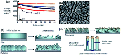 | ||
| Fig. 1 (a) Charge capacity versus cycle number for Si powder with different sizes (red: 5 nm, blue: 10 nm, orange: 10 nm after carbon coating, black circles: 20 nm). Reproduced with permission from ref. 31, copyright 2010, John Wiley and Sons. (b) SEM image of Si film cycled at C/3 for 40 cycles. Reproduced with permission from ref. 33, copyright 2010, American Chemical Society. (c, d) Schematics of morphological changes of Si over cycling. Reproduced with permission from ref. 34, copyright 2008, Nature Publishing Group. | ||
Si nanowires/nanotubes as anode have some advantages. Firstly, the small geometry allows better accommodation of the volume changes (Fig. 1c and d).34 Secondly, a direct contact between each wire/tube and current collector enables efficient charge transportation. Thirdly, the diffusion distance of Li+ is reduced. Nanowires, grown directly on stainless steel current collectors using the vapor–liquid–solid or vapor liquid template-free methods, demonstrated a high capacity of 4277 mA h g−1 during the first charge. It also showed good rate performance (2100 mA h g−1 at 1C) and good cyclability (3500 mA h g−1 for 20 cycles at C/5). Si nanotubes delivered 2600 mA h g−1 and 2100 mA h g−1 at C/20 and C/5 rate over 50 cycles, respectively.35 Furthermore, anisotropic expansion (smaller axial expansion, but larger radial expansion) was observed for Si nanotubes.
Embedding Si in a matrix that can buffer the volume expansion has been widely explored.36 Chan et al.37 uses the pyrolysis of sugar to coat carbon on Si nanowires. With additional carbon nanotubes as additive, the anode can remain a capacity of 1500 mA h g−1 over 75 cycles whereas the uncoated Si nanowires faded rapidly to 151 mA h g−1. Similarly, carbon coating has been utilized to stabilize the Si nanotubes/electrolyte interface and to promote formation of stable SEI.38 A reversible capacity of 3200 mA h g−1 and 89% capacity retention after 200 cycles at 1C was obtained in a full cell, using a LiCoO2 cathode. A rigid but ion-permeable SiO2, coated on the outer surface of Si nanotube (Fig. 2a),39 acts as a mechanical constraining layer to prevent the volume expansion, and thus can build up a thin and stable SEI layer. Such material demonstrated 88% capacity retention after 6000 cycles. Alternative to two-dimensional (2D) nanomaterials, mesoporous Si and other nanostructured Si, which can be produced in large scale and quantity, have emerged to address the issues of volume expansion. Yushin et al.40 used a hierarchical bottom-up approach to assemble Si spheres less than 30 nm on annealed carbon black substrates (Fig. 2b). Reversible capacity (1590 mA h g−1) of five times higher than that of the graphite anode and stable cycling were observed.
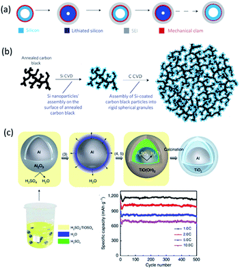 | ||
| Fig. 2 (a) Designing a mechanical constraining layer on the hollow Si nanotubes can enable the formation of a thin and stable SEI. Reproduced with permission from ref. 39, copyright 2012, Nature Publishing Group. (b) Schematic of Si–C nanocomposite granule formation through hierarchical bottom-up assembly. Reproduced with permission from ref. 40, copyright 2010, Nature Publishing Group. (c) Synthesis of Al@TiO2 and its half-cell performance.46 | ||
Interconnected Si hollow nanospheres, capable of accommodating large strain without pulverization, delivered a high initial discharge capacity of 2725 mA h g−1 and maintained 1420 mA h g−1 even after 700 cycles.41 Ma et al.42 reported nest-like Si nanospheres, prepared by a solvothermal method, with a first charge capacity of 3952 mA h g−1 and a fast capacity loss (only 36% capacity retention after 50 cycles at C/2). 3D porous bulk Si particles with a 40 nm thin pore wall to accommodate large strains can maintain a discharge capacity of 2800 mA h g−1 at 1C even after 1000 cycles.43 Monodisperse hollow porous Si nanoparticles (ca. 120 nm),44 formed by a template method and magnesiothermic reduction followed by Ag coating, showed a high specific capacity (3762 mA h g−1), long life time (99% retention after 99 cycles) and good rate performance (2000 mA h g−1 at 4 A g−1). Well-designed mesoporous Si with tunable porosity also exhibited a reversible capacity of 2111 mA h g−1 at C/5 and a promising stability over 50 cycles.45 Al/TiO2 yolk–shell nanoparticles with adjustable interspace were made recently by a one-pot synthesis route,46 which demonstrated significant improvement in capacity (1200 mA h g−1) and cycle life (average CE of ∼99.2% over 500 cycles at 1C, and 661 mA h g−1 remained after 500 cycles at 10C (Fig. 2c)).
Si-based intermetallic compounds, including Mg2Si, CaSi2, SiO, SiO2 and SiP2,47–49 have attracted intensive interest as promising anodes as well. For example, Mg2Si can deliver a large initial capacity of 1370 mA h g−1. A hydrogen-driven chemical reaction was used to produce hexagonal Li2MgSi anode material,50 which showed a discharge capacity 828 mA h g−1 after ball-milling. The capacity retention was 50% after 100 cycles. Park et al.49 reported a nanostructured SiP2/C composite. Lithiation of SiP2 proceeds through a topotactic transition, amorphization and conversion, leading to Li13Si4 and Li3P. A recombination reaction occurs upon delithiation. By controlling the cutoff voltage, high initial discharge and charge capacities of 1317 and 1137 mA h g−1, respectively, were observed. After 100 cycles, the composite still delivered a high reversible capacity of 980 mA h g−1.
2.2 Carbon-based anodes
Due to the abundance, thermal and chemical stability, good electronic conductivity, low cost and good reversibility,27 carbon materials still play an important role as anode materials. Nanosized carbon materials have features such as porous nature, reduction in diffusion distance, and increased number of storage sites for Li+,51 which enable higher capacity. A series of nanoporous hard carbons have been prepared by Tang et al.52 The obtained hierarchical porous carbons exhibited a maximum capacity of 503 mA h g−1 at C/5 and still delivered 332.8 mA h g−1 at 5C. Similarly, carbon nanorings with 20 nm outer diameters and 3.5 nm thick wall (Fig. 3) demonstrated a reversible capacity of 1200 mA h g−1 over 100 cycles at 0.4 A g−1.53 When increasing current density to 45 A g−1, the capacity dropped to 500 mA h g−1. Recently, Goodenough et al.54 produced a modified carbon by chemical introduction of ordered expanded nanographites and carbon microspheres with improved carbon interlayers alignment and H content. A high reversible capacity of 1180 mA h g−1 was preserved after 200 cycles at 0.1 A g−1 and it retained at 401 mA h g−1 after 1000 cycles even at 1 A g−1.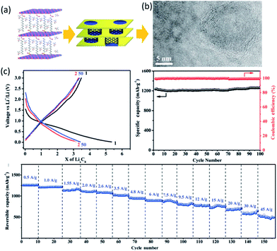 | ||
| Fig. 3 (a) Catalytic growth of carbon nanorings. (b) TEM image. (c) Cycling performance of the carbon nanorings. Reproduced with permission from ref. 53, copyright 2012, John Wiley and Sons. | ||
Since the discovery in 1991,55 single wall carbon nanotubes (SWCNTs) and multiple wall carbon nanotubes (MWCNTs) have been extensively investigated as both active anode materials and as additives. Ab initio studies showed such nanotube systems could substantially improve the capacity by utilizing both nanotube exteriors and interiors.56 Insertion and extraction capacities of 650 mA h g−1 have been achieved in coin cells using SWCNTs.57 Drilled MWCNTs with large quantity of functional groups by using CoOx as the oxidation catalyst showed a high capacity of 625 mA h g−1, long life time and high CE.58 Due to their outstanding flexibility, high tensile strength and good conductivity, a robust 3D composite network architecture can be built by incorporating CNTs with other active materials. Synergistic effects of cylindrical 3D nanostructured MoS2 directly grown on CNTs kept the porosity to Li+, prevented MoS2 aggregation and utilized high conductive CNTs.59 High specific capacity, excellent cycling property, and good rate capability were observed. Electrochemically prelithiated Fe2O3 nanoparticles confined in CNTs demonstrated the highest reversible capacity (2071 mA h g−1) ever reported for a Fe2O3 anode.60 The significantly improved Li+ storage was ascribed to the interfacial Li+ storage originating from the nanoconfinement of CNTs. TiO2,61 Co3O4,62 and NiO63 fabricated with CNTs were all reported to have a superior electrochemical performance towards Li+ storage.51
Thin graphene sheet with sp2-bonded carbon exhibits extraordinary electronic, mechanical and thermal properties. Experimental data showed that graphene itself can have a high reversible capacity of about 794–1054 mA h g−1.64 Owing to its high electronic conductivity, high surface area, and large number of active sites (edges and defects in graphene layers) for Li+ storage and short diffusion distance, graphene was used to hybridize with other active materials. Layered MoS2/graphene composites exhibited a high specific capacity of ∼1100 mA h g−1 at 100 mA g−1 and no capacity fading after 100 cycles. The synergistic effects between layered MoS2 and graphene preserved the high conductivity and greatly enhanced the electrochemical activity.65 3D porous monolayer MoS2–graphene composite aerogels also exhibited a large reversible capacity up to 1200 mA h g−1, and good cycling stability and rate performance.66 Metal oxide nanoparticles anchored on graphene surfaces in a hybrid form also showed significant improvement in electrode performance.67,68
2.3 Lithium transition metal oxide-based cathodes
Future applications of electronic devices and electric vehicles demand a significant power increase. As aforementioned, a shorter Li+ diffusion distance and larger electrolyte/electrode interface in cathode nanomaterials would enable much higher reaction rate. More importantly, size reduction could initiate certain phenomena which can't be observed in large particles. Olivine LiFePO4 has demonstrated reversible extraction of Li+ involving a Li-poor phase FePO4 and a Li-rich phase LiFePO4.3 Nucleation of the second phase and growth through interface motion during this process severely limited the rate capability of such materials. Ceder et al.69 discovered that ultrahigh discharge rate comparable to those of supercapacitors can be achieved when the LiFePO4 particle size was reduced to around 50 nm (Fig. 4a). Further study proved that a nonequilibrium solid solution phase70 that span the entire composition between two thermodynamic phases71 can be formed in nanoparticulate LiFePO4 at high rates (Fig. 4b and c).72 Similar phenomenon was also observed in nanosized NaxFePO4 and a high rate Na insertion/desertion could be achieved.73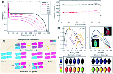 | ||
| Fig. 4 (a) Rate capability and capacity retention for LiFePO4 synthesized at 600 °C. Reproduced with permission from ref. 69, copyright 2009, Nature Publishing Group. (b) Phase transformation from LiFePO4 (blue) to FePO4 (red). Reproduced with permission from ref. 71, copyright 2014, The American Association for the Advancement of Science. (c) Quantifying the insertion kinetics and exchange current density. Reproduced with permission from ref. 72, copyright 2016, The American Association for the Advancement of Science. | ||
Nanosized LiFePO4 has also been utilized as a coating layer providing a fast Li+ transportation pathway. Pan et al.74 managed to coat 50 nm crystal oriented LiFePO4 onto LiNi0.5Mn0.3Co0.2O2 (NMC532) and created a core–shell cathode material (Fig. 5a). It showed superior cycling stability with a discharge capacity of 168.5 mA h g−1 (cycling between 3 and 4.5 V, 7.2% capacity loss) and 173.3 mA h g−1 (cycling between 3 and 4.6 V, 8.5% capacity loss) after 150 cycles at C/3, respectively (Fig. 5b).
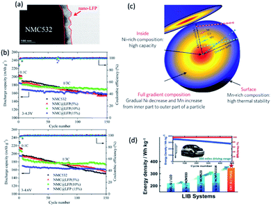 | ||
| Fig. 5 (a) TEM image of NMC@LFP, and (b) cycling performance of pristine NMC532 and NMC@LFP (5, 10, 15%) at different rates and cut-off voltages. Reproduced with permission from ref. 74, copyright 2016, American Chemical Society. (c) Schematic diagram of the FCG lithium transition-metal oxide particle with Ni-rich core and Mn-rich outer layer. Reproduced with permission from ref. 75, copyright 2012, Nature Publishing Group. (d) Schematic illustration of LIBs based on CNT–Si anode and two-sloped FCG cathode for vehicle application.76 | ||
Another example that illustrates the benefits of nanostructured materials is the full concentration gradient (FCG) layered metal oxide (Fig. 5c).75 Although Ni-rich layered lithium transition metal oxides have high specific capacity and relatively low cost, they suffer severely from poor thermal stability at fully charged state and insufficient cycle life. Using a nano-functional full-gradient approach, high energy density of the Ni-rich core and the high thermal stability and long life of the Mn-rich outer layers can be harnessed. High rate performance could also be realized from aligned needle-like nanosized primary particles.75 A full cell with an energy density of 350 W h kg−1 and excellent capacity retention for 500 cycles at 1C has been demonstrated accordingly (Fig. 5d).76 1D nanowire LT-LiCoO2 based on SBA-15 and highly ordered spinel LiNi0.5Mn1.5O2 array also showed superior electrochemical performance compared with bulk materials.77,78
2.4 Nanostructures in Li–S batteries
The maximum energy that can be stored and delivered in current LIB cathodes (such as layered oxides, polyanionic and spinel materials) is still too low to meet some demands like transportation applications.79 In contrast, Li–S batteries (S + 2Li+ + 2e− → Li2S) can deliver a theoretical energy density of 2567 W h kg−1 or 2199 W h L−1,80 making Li–S promising for future battery systems. However, its large scale application is impeded by three main challenges: (1) sluggish kinetics ascribed to the insulating nature of S and its lithiated products Li2Sx; (2) collapse in electrode structure due to large volume change during lithiation; and (3) a shuttle effect and rapid capacity fade due to dissolution of intermediates in the electrolyte (Fig. 6a).81 Such challenges can be tackled by rational design of nanostructures with interconnected electron pathways and ion diffusion channels.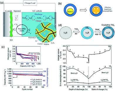 | ||
| Fig. 6 (a) Illustration of the dissolution and shuttling of polysulfides in a Li–S cell.81 (b) A yolk–shell structure with internal void space can accommodate the volume expansion of sulphur for effective trapping of polysulphides. Reproduced with permission from ref. 94, copyright 2013, Nature Publishing Group. (c) Electrochemical performance of Ti4O7/S electrodes. Reproduced with permission from ref. 98, copyright 2014, Nature Publishing Group. (d) Schematic of Li2S@TiS2 core–shell nanostructures, and reduced loss of total sulfur into the electrolyte detected at various intermediate stages of cycling, in comparison with bare Li2S cathodes. Reproduced with permission from ref. 99, copyright 2014, Nature Publishing Group. | ||
The first category of nanostructured sulfur cathodes lies in carbon materials and sulfur nanoparticles. It has been reported that sulfur nanoparticles encapsulated in nanoporous carbon matrix with ultrahigh sulfur loading (88.9 wt%) exhibited a high overall discharge capacity of 649.4 mA h g−1.82 The porous structure enabled higher capacity retention (84.6%) and CE (97.4%) after 50 cycles at C/10, attributed to the resulting electronic and ionic transfer channel. Sulfur content was further increased to 90% in a composite with nanoscale distribution of S in 3D porous graphitic carbon. This material has a high specific capacity (1382, 1242 and 1115 mA h g−1 at 0.5, 1 and 2C, respectively), long cycling life (capacity decay of 0.039% per cycle over 1000 cycles at 2C), and excellent rate capability.83 Carbon nanotubes,84 carbon nanofibers85 and hollow spheres44 also have demonstrated superior electrochemical performance with high specific capacity, excellent cycling stability and rate capability. To strengthen the interaction between nonpolar carbon and polar sulfur cluster and polysulfides, Cui et al. modified the hollow carbon nanotube surface with amphiphilic polymers,86 which allowed lithium sulfides to bind strongly with the carbon surface and resulted in less than 3% decay over the first 100 cycles at C/2. The capacity retention was >80% for more than 300 cycles with CE ∼ 99%. Carbon surface can be functionalized via elemental doping to create chemical anchoring sites. Nitrogen-doping on mesoporous carbon nanospheres and carbon nanotubes endowed electron-donating ability.87 The as-obtained composite delivered a high initial specific capacity (1480 mA h g−1) and excellent cycling stability (90% retention over 200 cycles after activation) with 70 wt% sulfur and 5 mg cm−2 areal loading. Other doping elements (such as S, B, O and P) have also been extensively explored for Li–S batteries. Graphene nanosheets with heteroatom doping built strong bound interface with sulfur and polysulfide to optimize the electrochemical performance. A high initial discharge capacity of 1302 mA h g−1 and retained discharge capacity of 978 mA h g−1 after 200 cycles at C/10 were obtained in a recent work.88
To further increase the anchoring ability of host materials, nanostructured polar inorganic materials such as metal oxides and sulfides have been investigated. Stronger adsorption of host materials towards polysulfides renders higher sulfur utilization and longer life span. In an early work,89 mesoporous silica SBA-15 (ref. 90) was used as a reservoir for S/C nanocomposite. The initial discharge capacity of the cell was 960 mA h g−1 and a capacity of about 650 mA h g−1 was maintained after 40 cycles. The sulfur content in the electrolyte was reduced from 54% to 23% with the presence of SiO2. In another work,91 a bifunctional MnO2 shell with 50 nm thick MnO2 shell coated on sulfur particles provided physical confinement and chemical interaction and demonstrated excellent efficiency in trapping the polysulfides even with 85% sulfur loading. In addition, stable Li–S cycling performance has been achieved by directly crystallizing nanoshells of MnO2 on micrometer-sized sublimed sulfur with 480 mA h g−1 after 800 cycles and only 0.048% capacity fade per cycle. Due to their intrinsic low electronic conductivity, conductive scaffold is often combined to create a robust electrode. Hollow carbon fibers (HCF) filled with intrinsic insulating MnO2 nanosheets was recently reported by Lou et al.92 With 71 wt% and 3.5 mg cm−2 of sulfur, the MnO2@HCF/S composite electrode delivered a specific capacity of 1161 mA h g−1 or 4.1 mA h cm−2 at C/20 and maintained stable cycling performance at C/2 over 300 cycles. Attributed to its good electronic conductivity as well as the polar surface, titanium oxides have also been applied extensively in Li–S batteries. For example, the soluble lithium polysulfides are preferentially absorbed within the pores of the nanoporous titania at intermediate discharge/charge. The addition of TiO2 with a 5 nm pore diameter enabled 37% improvement in capacity retention after 100 cycles.93 Using a yolk–shell architecture with internal void space to accommodate the volume expansion of sulfur (Fig. 6b), Cui et al. demonstrated an initial specific capacity of 1030 mA h g−1 at C/2 and CE of 98.4% over 1000 cycles in a coin cell with 0.4–0.6 mg cm−2 of sulfur.94 The capacity decay after 1000 cycles was 0.033% per cycle. Hydrogen treatment has been proven effective to produce Ti3+ and improve the electronic conductivity of TiO2.95 Hydrogen-treated TiO2 inverse opal with small dimensions of nanopores effectively confined polysulfides by both physical trapping and surface chemical adsorption.96 The fabricated sulfur cathode could deliver a high initial specific capacity of about 1100 mA h g−1, with a reversible capacity of about 890 mA h g−1 after 200 cycles at C/5. The CE was also maintained at about 99.5% during cycling. TiO2 nanotubes, nanofibers, hollow spheres and nanoparticles have all been reported to improve the performance of Li–S batteries. Conductive metallic Magneli phase Ti4O7 is another promising sulfur host.97 Nanocrystalline Ti4O7 impregnated with 60–70 wt% sulfur provided a discharge capacity of 1070 mA h g−1 at intermediate rates and good capacity retention (Fig. 6c).98
Given the conductive nature of metal chalcogenides and stronger sulfiphilic property of these sulfur containing species, metal sulfides offer more benefits and constitute another promising family as host materials for Li–S batteries. Using 2D conductive TiS2 to encapsulate Li2S core particles in a 20 nm thick shell (Fig. 6d),99 a high specific capacity of 503 mA h g−1 under 4C as well as high areal capacity of 3 mA h cm−2 was obtained. A thinner shell would have a faster fade rate due to its insufficient thickness to protect the core, while a thicker shell hindered rate performance. To further increase sulfur loading, S8 was infused into nanoporous TiS2 foams.100 The hybrid cathodes demonstrated high areal specific capacity (9 mA h cm−2) and capacity retention, even with ∼40 mg cm−2 and high current density (10 mA cm−2). Another highly conductive Co9S8 could form an interconnected graphene-like nano-architecture,101 where the 3D interconnected structure with hierarchical porosity not only manifested enhancement in the cycling stability (fade 0.045% per cycle over 1500 cycles at C/2) compared to standard porous carbons but also realized a high-loading sulfur electrode (up to 75 wt% sulfur and 4.5 mg cm−2). Another host material is CoS2. When incorporated into carbon/sulfur cathodes, a slow capacity decay of 0.034% per cycle at 2C and a high initial capacity of 1368 mA h g−1 at C/2 were achieved.102 FeS2,103 ZnS,104 WS2 (ref. 105) and other various sulfides80 have been used as host materials as well. Although nanostructured carbon, metal oxides and sulfides have demonstrated outstanding ability to create a cathode with high sulfur utilization and long cycle life, material abundance, areal loading and viable anode should be considered towards the practical application of Li–S batteries.
3. Nanostructured coatings for advanced electrodes
Many electrode materials of LIBs encounter critical issues including: huge volume expansion, low ionic/electronic conductivities, and/or side reactions with electrolytes etc. Surface modification of electrode materials by employing a thin nanoscale layer has proved effective way for improving the electrochemical performance of LIBs.106 Different types of nanoscale coatings depending on the nature of electrodes have been developed, such as carbon based materials, oxides, fluoride, phosphates, and other ionic and electronic conductive species.107 Associated with these benefits of the coating chemistries, the structure design for effectively combining the advantages of the coatings and active materials, such as core–shell108 and hollow shell,109 has been also performed to engender much improvement of the LIB electrodes. This section reviews the recent progress in nanostructured coatings for developing high-performance LIB components, including metallic anodes, metal oxide anodes, Li-rich layered oxide cathodes, high-voltage spinel cathodes, and sulfur based cathodes. Great interests have been put in multifunctional capabilities and unique characteristics of the surface modifications for advanced LIB techniques.3.1 Thin films on metallic Li and Li-alloy-based anodes
Extensive research has been focused on battery chemistries with metallic anodes (Li, Si, Ge, Sn, etc.) mainly due to their high specific capacities. For Li metal, it is an attractive anode material, possessing a high theoretical specific capacity (3860 mA h g−1), low density (0.534 g cm−3), and the lowest electrochemical potential (−3.04 V vs. standard hydrogen electrode). Although metallic Li anode is highly interesting for high-energy batteries such as Li–S battery, Li–air battery, and other advanced systems, the dendritic Li formation and high chemical reactivity of Li with most electrolytes remain challenging. Graphene,110 polymer membranes111 and ceramic electrolytes112 have been used as chemically and physically protective layers on Li anode. However, there still exist issues with safety and efficiency during prolonged cycles. More efforts to build a robust surface layer to suppress the growth of Li dendrites and enhance compatibility between Li anode and electrolyte after long-time operations are driven for enabling a variety of batteries using Li metal with high energy storage.Recently, Yan et al.113 demonstrated a promising novel electrode design by growing 2D atomic crystal layers including hexagonal boron nitride (h-BN) and graphene directly on Cu metal current collectors. They used the method of chemical vapor deposition (CVD) developed recently for synthesis of large-area h-BN. The thickness of the film was determined to vary from 1 to 10 atomic layers, depending on the growth time and pressure. Smooth Li metal deposition without dendritic and mossy Li formation was realized. Their results showed stable cycling over 50 cycles with CE ∼ 97% in organic carbonate electrolyte with current density and areal capacity up to 2 mA cm−2 and 5 mA h cm−2, respectively.114 Both graphene and h-BN were summarized with the following attractive properties: (1) they are known to be chemically inert and stable against most chemicals including Li metal; (2) their single atomic layers have very strong mechanical strength, resulted from strong interlayer bonding; (3) no chemical species can diffuse through the layers and Li metal cannot move through the ring pore, either; and (4) despite the large in-plane strength, 1–10 layers of graphene and h-BN are highly flexible due to their ultrathin thickness (<10 nm).
Liu et al.114 reported a new strategy to address the issue of dendrite growth of metallic Li by a polyimide-coating layer with vertical nanoscale channels of high aspect ratio. The nanosized channels with high aspect ratio were able to divide the space above the anode into small confinements. Thus, Li+ could prefer to move along the normal direction of the electrode rather than the parallel direction. The magnitude of Li+ flux in each nanochannel could be relatively homogeneous during Li deposition, resulting in a uniform nucleation and growth, and the Li deposit could not grow into elongated metal filaments. Meanwhile, the volumetric expansion of the Li deposition could be also partially negated within the volume of the pores due to the fixed thickness of the coating. More importantly, the porous polymer membrane contacted with the current collector tightly, which avoided the possibility of its lift up by the deposition of Li metal. Their results showed that the cells with modified electrodes exhibited significantly improved CE of 97.6% over 240 cycles, 92.9% over 150 cycles, and 88.6% over 140 cycles, respectively, at current densities of 1, 2, and 3 mA cm−2. In sharp contrast, the cells using bare electrode showed rapid decay after 125, 75, and 50 cycles, respectively. Subsequently, they reported a nanoporous, flexible, and electrochemically stable coating of silica@poly(methyl methacrylate) (SiO2@PMMA) core–shell nanospheres as a stable layer on Li metal anode.115 The cell with bare Cu electrode showed a gradual decrease in CE, which eventually decayed to 68% and 56% after 50 cycles at 0.5 and 1 mA cm−2, respectively. For the Cu electrode coated with SiO2@PMMA nanospheres of 450@20, 550@10, and 550@20 nm, the CE after 50 cycles was about 87%, 83%, and 81% at 0.5 mA cm−2, respectively. When tested at a higher current density of 1 mA cm−2, a CE of 90% after 50 cycles was achieved for the modified electrode with 550@10 nm nanosphere coating. It was well illustrated that the core–shell structure produced a synergistic effect between the core and shell to prevent Li dendrite growth. Compared to bare electrode, dendritic Li with large specific surface area could continuously decompose the electrolyte, resulting in low CE and short cycle life (Fig. 7a). An explanation for the beneficial effect of the coating of SiO2@PMMA core–shell nanospheres were proposed, as shown in Fig. 7b. They demonstrated that the SiO2 core with high Young's modulus could suppress Li dendrite growth. The nanoscaled pores formed by coating SiO2@PMMA core–shell nanospheres were so small that Li dendrites cannot penetrate the membrane, but Li+ could diffuse without being blocked. The PMMA shell can hold the SiO2 spheres together to form a robust and flexible membrane that could accommodate volume change during Li deposition/dissolution without cracking and could prevent reaction between SiO2 and Li metal.
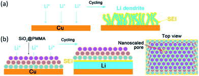 | ||
| Fig. 7 Schematic diagrams of different Li anode structures. (a) A thin film of SEI layer forms on bare Cu surface. Volumetric changes during the Li deposition can easily break the SEI layer, leading to ramified growth of Li dendrites and consumption of the electrolyte. (b) Modified Cu electrode coated with a SiO2@PMMA nanosphere layer. The volumetric change of Li deposition/dissolution is accommodated by the coating of SiO2@PMMA nanospheres. Nanoscaled pores are able to suppress lithium dendrites. Each monolayer is given a different color to indicate the packing of nanospheres. Reproduced with permission from ref. 115, copyright 2017, American Chemical Society. | ||
Recently, Si has been found to offer ten times more energy density as compared to carbon anode. However, Si anode suffers two major drawbacks: (1) low electronic conductivity; (2) large volume expansion during charging. To utilize the high energy density of Si while minimize its drawbacks, various Si–carbon composites116–118 have been developed and demonstrated to have enhanced performance. Unfortunately, cracking associated with volume expansion generally still occurs, leading to poor cycle stability and rate capability. To further improve electrochemical properties of Si anode, thin surface coatings with various materials, such as oxide119,120 and carbon based materials,121 have attracted considerable attention as a promising candidate approach to accommodate the large volume expansion and enhance the cyclability of Si electrodes. Xiao et al.122 deposited a 5 nm Al2O3 coating on Si anode by means of atomic layer deposition (ALD), and characterized the SEI features for both bare and Al2O3-coated Si anodes using time-of-flight secondary ion mass spectrometry. In contrast, the SEI thickness of Al2O3-coated Si anode was only a few nanometers, which was obviously smaller than that of bare Si anode (about 20–30 nm). The SEI layer on the Al2O3-coated Si anode contained much less Li2CO3 than that on bare Si anode. They ascribed this to the insulating Al2O3 coating, preventing electrons from reaching the anode surface to engender the decomposition of the electrolyte. Moreover, LiAlO2 was demonstrated to form in the top surface of SEI on the Al2O3-coated Si anode, reducing the energy barriers against the insertion of Li+ and thus enhancing the kinetics of Li+ transfer. However, the details of these reactions at the atomic scale have not yet been understood.
Liu et al.123 encapsulated Si anode materials with conductive polymer that had the elastic advantage during the charge and discharge process of Si anode. Meanwhile, conductive additives were not needed for the modified Si anode because of good conductive pathway to all the Si particles provided by the conductive polymer. This is an efficient way to enhance the loading of Si and increase the energy density. Combined with the high theoretical capacity of Si core (4200 mA h g−1), Chang et al.124 deposited multilayered reduced graphene oxide (RGO) with Si nanoparticles in between each layer, intending to suppress the issue of volume expansion. The RGO layers closest to each Si nanoparticle could allow enough space for the Si nanoparticle to expand during the lithiation process. The RGO layers away from each Si nanoparticle could provide mechanical stability due to the formation of 2D networks of graphite based on van de Waals forces. Moreover, the RGO layers possessed high electrical conductivity favoring the connection of each isolated Si nanoparticle.
For TiN in particular, its high electrical conductivity (resistivity of 25 μΩ cm) is one of its most important attributes. Nanoscale TiN coating was deposited on Si NWs by ALD, and to a lesser extent by magnetron sputtering. A 5 nm thick TiN coating resulted in optimum cycling capacity retention (55% vs. 30% for the bare Si NWs, after 100 cycles) and CE (98% vs. 95%, at 50 cycles), also enhanced rate capacity retention (e.g. 740 mA h g−1 vs. 330 mA h g−1, at 5C). The results indicated that the thin TiN coating significantly improved the cycling performance of Si NWs anode. Moreover, they employed a variety of advanced analytical techniques such as electron energy loss spectroscopy to elucidate the origin of these effects. The conformal 5 nm TiN remained sufficiently intact to limit the SEI growth, which in turn both improved the overall CE and reduced the life-ending delamination of the nanowire assemblies from the underlying current collector.125
To improve the electronic conduction properties of nanostructured Si anode, one way is to use metallic coatings.126 A metallic Cu coating partially deposited on the Si NWs was reported by McDowell et al.127 The Cu coating is only deposited on one side of the Si NWs for remaining transport pathways of Li+. It was observed that the width and length of the Cu-coated Si NWs almost unchanged during lithiation. Hence, the Cu coating not only provides high electrical conductivity in the composites, but also maintains structural integrity.
Jeong et al.128 encapsulated Si nanoparticles with TiO2−x/C nanocomposite to form core–shell structured Si nanoparticles@TiO2−x/C (SiNPs@T/C) mesoporous microfiber composite by an electrospinning method. The cycling performance and rate capability of the SiNPs@T/C were exhibited in Fig. 8a and b. For comparison, the simply mixed Si–TiO2–C electrode in the same weight ratio with the SiNPs@T/C electrode (the Si content in the SiNPs@T/C was ∼43%) was also tested. When cycled at C/5 and 1C, the SiNPs@T/C displayed excellent cycling performance with almost the same capacity retention (i.e. 90% of the initial capacity after 50 cycles). The SiNPs@T/C also exhibited outstanding rate capability, where a high capacity of 939 mA h g−1 was observed even at 12C (12 A g−1), which is 89% of the initial capacity at C/5. The SEM images of the SiNPs@T/C particle and the cross section of the SiNPs@T/C electrode after 50 cycles were shown in Fig. 8c–e. Significant collapse of the fibrous core–shell structure cannot be observed even after 50 cycles. Also, the volume expansion after the 50th discharge was still ∼53%, which was almost the same as the value after the first discharge step. The improved electrochemical properties were mainly ascribed to the structure reserving void space therein, as well as oxygen deficient TiO2−x and carbon providing an enhanced electrical pathway. Similarly, the double shells (i.e. carbon inner shell and TiO2 outer shell) were deposited on Si anodes, avoiding the direct contact of Si with electrolyte. With this architecture, the advantages of core–shell–shell nanostructures lay in the presence of the internal mesoporous space and the mechanically robust TiO2 layer. The elaborate double-shell Si nanoparticles were proven to show excellent Li-storage properties. It delivered high reversible capacity of 1726 mA h g−1 over 100 cycles, with outstanding cyclability of 1010 mA h g−1 at 0.42 A g−1 and high CE of >98% after 710 cycles.129 The carbon inner shell was considered to improve overall conductivity of the Si-based electrode and the TiO2 outer shell served as a rigid layer to achieve high structural integrity of the double-shell structure.
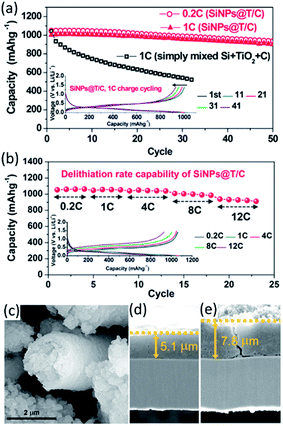 | ||
| Fig. 8 (a) Capacity retention of SiNPs@T/C during cycling and the corresponding voltage profiles (inset). (b) Rate capability of SiNPs@T/C and the corresponding voltage profiles (inset). (c) SEM image of SiNPs@T/C after 50 cycles (lithiated state). The cross-sectional SEM images of SiNPs@T/C electrode (d) before cycling and (e) after 50 cycles (lithiated state). Reproduced with permission from ref. 128, copyright 2014, American Chemical Society. | ||
3.2 Thin films on metal oxide anodes
Metal oxides used as anode materials for LIBs have received extensive attention due to their higher theoretic specific capacities than graphite and relatively smaller volume change than metal anodes. Unfortunately, they usually suffer from a severe capacity fade and poor cycling performance caused by volume expansion or the risk of secondary reactions during cycling. The widely used strategy is to coat the anodes with carbon nanomaterials130,131 that could accommodate the volume change based on their elastic features and increase the electronic conductivity of the anode materials, resulting in a better capacity retention and cyclic performance. For example, it was found that polymerization of pyrrole monomers lead to the simultaneous oxidation of Fe2O3 and polypyrrole (PPy) coating process, resulting in the successful formation of hierarchical nanocages of Fe3O4@PPy. By using as-prepared hierarchical Fe3O4@PPy nanocages as the anode, they exhibited excellent electrochemical performances, such as improved large reversible capacity, rate capability, and long-term cycling stability.132 Similarly, the synthesized Mn3O4 samples with a tetragonal structure (space group I41/amd) displayed nanorodlike morphology, with a width of 200–300 nm and a thickness of 15–20 nm. The carbon layers with a thickness of 5 nm could be homogeneously coated on the Mn3O4 nanorods, and the Mn3O4@C samples displayed enhanced capacity retention on cycling. Even after 50 cycles, the products remained stable capacity of 473 mA h g−1, which was as much three times as that of pure Mn3O4 samples.133 Besides carbon, surface modification with oxides, solid electrolytes and other compounds has been also proved to be effective for improving the electrochemical performance of metal oxide anodes.SnO2 anode, possessing a high theoretical capacity of 782 mA h g−1, however, has a large volume expansion of ∼300%, which would result in pulverization and deterioration of the active materials during cycling. Recently, Zhu et al.134 reported hierarchically porous TiO2 nanotube@SnO2 nanoflake core/branch arrays as the LIB electrode, which were synthesized with the ALD process and sacrificial Co2(OH)2CO3 nanorod template. The hydrothermally grown SnO2 were intimately connected with the vertical-standing TiO2 nanotubes, resembling a forest on the nanoscale (Fig. 9). The spaces between SnO2 nanoflakes could buffer the volume expansion and also assured full access by Li+. The core/branch material exhibited a specific discharge capacity of 498 mA h g−1 at 3.2 A g−1. When the current density was set back to 0.2 A g−1 after 50 cycles, the loss of discharge capacity of the core/branch electrode was about 200 mA h g−1. For the commercial powder, the capacity dropped to near zero when the current density increased above 0.8 A g−1. The results indicated that the outer TiO2 may block or retard the direct access of Li+ to SnO2 that was supposed to be the main capacity contributor. Meanwhile, SnO2 was released outside of the core/shell structure to assure a direct contact with Li+, in order to achieve large contact area between SnO2 and the electrolyte. Other works aiming at protecting SnO2 from collapse by enwrapping SnO2 inside TiO2 have been also reported.135–137
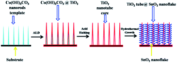 | ||
| Fig. 9 Schematics of the fabrication process of TiO2 nanotube@SnO2 nanoflake core-branch nanostructures. Reproduced with permission from ref. 134, copyright 2014, Elsevier. | ||
A ZnO nanorod anode was coated with a ∼11 nm TiO2 layer by ALD. An increased reversible capacity of the coated anode could be observed with 447 mA h g−1 compared to 358 mA h g−1 for the uncoated one.138 The thin TiO2 layer could not only sustain the mechanical integrity of ZnO nanorods, but also acted as an “artificial” SEI reducing the degree of reactions between ZnO and the electrolyte, and thereby improving the cycle stability. It was demonstrated that excellently structural stability and semiconducting nature of TiO2 materials made it a suitable backbone or protective layer for other metal oxides through smart hybridization. An effective strategy to overcome the degradation of MoO3 nanorod anodes at high-rate cycling was achieved by HfO2 surface coating using ALD. At 1.5 A g−1, the specific capacity of HfO2-coated MoO3 electrodes (657 mA h g−1) was much higher than that of bare MoO3 electrodes (460 mA h g−1) after 50 cycles. Furthermore, they observed that HfO2-coated MoO3 electrodes tended to stabilize faster than bare MoO3 electrodes because nanoscale HfO2 layer prevented structural degradation of MoO3 nanorods.139
Of particular interest, Xu et al.140 employed a sulfur-assisted decomposition process to create agglomerates of large (200–500 nm) yet highly nanoporous 3D MoO2 single crystals partially covered with a few atomic layers of MoS2 (“MoS2/MoO2 nanonetworks”). As a highly reactive species toward Mo, S would disrupt the orderly growth of largely and fully dense MoO2 crystallites, rather promote highly porous nanostructures. Meanwhile, MoS2 was also a highly active electrode materials, which meant that the formation of any secondary sulfide phase would also contribute to the overall capacity. At 100 mA g−1, the MoS2/MoO2 nanonetworks exhibited a reversible discharge specific capacity of 1233 mA h g−1, with only 5% degradation after 80 cycles. Moreover, at fast discharging rates of 0.2 and 0.5 A g−1, the capacities were 1158 and 826 mA h g−1, respectively. In addition, solid electrolytes have been also used as protective coatings for metal oxide anodes. Lithium phosphorus oxynitride (LiPON) as a nanocladding layer was successfully coated on a 3D MWCNT@RuO2 electrode by means of ALD. The 17 nm ALD LiPON layer minimized parasitic SEI formation, provided facile ion transport through the LiPON solid electrolyte, and constrained electrode nanostructure. Without LiPON protection, the MWCNT@RuO2 electrode lost capacity with cycling, retaining only 55% of the second discharge capacity after 20 cycles. In striking contrast, the MWCNT@RuO2@LiPON retained >95% of the second cycle capacity after 50 cycles. Such favorable capacity retention is unusual for a conversion electrode, where lithiation involves insertion of 4Li+ per transition metal, significant volume expansion, and chemical/structural transformation of materials and phases.141
3.3 Surface coatings of Li-rich layered oxide cathodes
Li-rich layered oxides, xLi2MnO3·(1 − x)LiMO2 (M = Mn, Co, Ni), have drawn extensive attention recently owing to their larger specific capacity of over 250 mA h g−1.142 However, sluggish reaction kinetics resulted from intrinsic low electronic conductivity and slow Li+ diffusion due to the occupancy of the excess Li+ in the transition metal layer, blocking the flow of electrons and diffusion of Li+ in the Li-rich layered oxides.143,144 To improve its electrochemical characteristics, different surface coatings with oxides (Al2O3,145 Li2SiO3,146 Li2ZrO3 (ref. 147) and CeO2 (ref. 148)), fluorite (AlF3 (ref. 149)), phosphates150 and metallic Al151 have been reported to improve the electrochemical performance of Li-rich layered materials. However, the surface modification has not been optimized, and yet cannot achieve high capacity and remarkable rate capability and enhanced cycle performance simultaneously. New effective way of surface modification would be anticipated.Recently, Li-rich Li1.2Mn0.525Ni0.175Co0.1O2 (Li-rich NMC) material was coated by a nanometer layer coating of a Li+ conducting solid electrolyte, LiPON, by RF-magnetron sputtering method.152 The LiPON coated Li-rich NMC composite electrode showed stable reversible capacities of >275 mA h g−1 when cycled to 4.9 V over 300 cycles, and showed improvements in the rate performance compared to the uncoated ones at current rates of 5C and higher. Increasing the thickness of the LiPON layer would lead to capacity fade due to increasing electronic resistance.
The active Li2MnO3 in the layered material Li1.2Ni0.13Mn0.54Co0.13O2 reacted with hydrazine vapor that was employed to extract Li+ from the surface region. Thus, a Li-deficient and proton-incorporated layer was formed on the surface. The removal of the incorporated protons and migration of transition metal ions from the transition metal layer into the Li layer at 300 °C resulted in a spinel Li1−xM2O4 phase on the surface of the layered material. Compared to the pristine material, the surface modified sample annealed at 300 °C delivered a larger initial discharge capacity of 296 mA h g−1 with a CE of 89.5% and a better rate performance (192 mA h g−1 at 0.4 A g−1).153
Olivine-type LiMnPO4 is regarded as one of the most promising electroactive materials with a high charge potential, in analogy to that of Li-rich layered oxides. The surface modification via a thin amorphous Li–Mn–PO4 with a thickness of 5–7 nm was introduced onto Li-rich layered oxide Li(Li0.17Ni0.25Mn0.58)O2,154 leading to enhanced performance. With increasing calcination temperature after the surface coating, a strong interaction could be induced on the interface between the amorphous layer and the top surface of Li(Li0.17Ni0.25Mn0.58)O2 grains. The initial discharge capacity of the as-prepared sample was 261 mA h g−1 with CE of 80.7%. For the coated sample after calcination at 400 °C, the initial discharge capacity and CE were 293 mA h g−1 and 85.5%, respectively. The maximum discharge capacity of the as-prepared Li(Li0.17Ni0.25Mn0.58)O2 was 97.9 mA h g−1 at 5C rate (1.5 A g−1). For Li–Mn–PO4-coated samples after calcination at 400 and 500 °C, the maximum discharge capacities at 5C were 158.8 and 140.5 mA h g−1, respectively.
Instead of classic physical-adsorption/deposition techniques, Guo et al.155 proposed a novel chemical-adsorption strategy to synthesize double-shell modified Li-rich layered cathodes with enhanced mass transfer kinetics. Based on experimental measurement and first-principles calculation, MoO2S2 ions were proved to join the layered phase via chemical bonding. Specifically, the Mo–O or Mo–S bonds could flexibly rotate to bond with the cations in the layered phase, leading to the good compatibility between the thiomolybdate adsorption layer and layered cathode. The double-shell modified sample delivered an enhanced discharge capacity almost twice as much as that of the unmodified one at 1 A g−1 after 100 cycles, demonstrating the superiority of the surface modification based on chemical adsorption.155
The surface nitridation was introduced into a Li-rich layered oxide Li(Li0.17Ni0.25Mn0.58) via heating at 400 °C in the ammonia atmosphere. It was demonstrated that a trace amount of nitrogen existed on the surface of the active material after the nitridation treatment. After 60 cycles, the discharge capacity of the nitrided sample still retained at 256 mA h g−1, showing good capacity retention. On the contrary, the discharge capacity of bare sample quickly decreased from 224 to 141 mA h g−1 after 57 cycles.156 Therefore, the surface nitridation was an effective way to improve the electrochemical performance of the electroactive materials for LIBs. The same strategy adapted in this work could be helpful to explore and develop desired cathode materials for new generation LIBs.
Wu et al.157 proposed a biomimetic design and versatile synthesis strategy of ultrathin spinel membrane-encapsulated layered Li-rich cathode material. A polymer dispersant (polyvinylpyrrolidone) was initially dispersed on the pristine layered Li-rich materials Li1.2Mn0.6Ni0.2O2 to assist the subsequent homogeneous decoration of the manganese salt. Eventually, spinel Li1+xMn2O4 membrane could be yielded on the surface after heat treatment, due to the ion diffusion from the bulk. Therefore, surface modification with an ultrathin nanolayer of spinel Li1+xMn2O4 as a “membrane” encapsulating on a layered Li-rich cathode were explored as shown in Fig. 10a. TEM image of the ultrathin spinel membrane encapsulated-layered Li-rich cathode (Fig. 10b) showed the existence of a homogeneously ultrathin layer. As shown in Fig. 10c, the pristine sample showed a poor rate capability, a dramatic capacity drop with the increasing of C-rate, and nearly no capacity was obtained at a 10C rate. When cycling back to C/10 rate, a capacity of only 190 mA h g−1 was maintained. On the contrary, the spinel-encapsulated sample yielded maximal discharge capacities of 247.9 mA h g−1, 223.8 mA h g−1, and 200.1 mA h g−1 at 1C, 2C, and 5C rates, respectively. Surprisingly, it delivered a high capacity of 124.8 mA h g−1 even at 10C, over 40% of the capacity at C/10 (inset of Fig. 10c). It even maintained 275 mA h g−1 when returned to the C/10 rate. Hence, the spinel-encapsulated material combined advantages of high capacity from the bulk layered Li-rich cathode and high rate capability from the spinel membrane. It was demonstrated that this high Li+ conductive membrane could rapidly transport Li+ between the electrolytes and the layered bulk as a “Li+ pump”.
 | ||
| Fig. 10 (a) Schematic structure, and (b) TEM images for spinel-encapsulated cathode material. (c) Rate performance of the pristine and spinel-encapsulated samples, at a fixed charge rate of C/10 and different discharge rates. Reproduced with permission from ref. 157, copyright 2014, American Chemical Society. | ||
Xia et al.158 fabricated a novel Layered@Spinel@Carbon (LSC) heterostructured cathode material via a carbothermal reduction route. A spinel phase in situ formed along the layered bulk/carbon interface with the assistance of carbon reduction, which expedited Li+ (de)intercalation between electrolyte and Li-rich layered cores. Thus, the LSC material comprised a core of Li-rich layered oxide (R![[3 with combining macron]](https://www.rsc.org/images/entities/char_0033_0304.gif) m), a spinel phase (Fd
m), a spinel phase (Fd![[3 with combining macron]](https://www.rsc.org/images/entities/char_0033_0304.gif) m) interlayer and a carbon nanocoating (Fig. 11). The rate capability was galvanostatically investigated to 4.8 V from 0.2 to 20C. When discharged at 2C, the LSC sample delivered a higher discharge capacity of 273.2 mA h g−1, whereas the pristine sample showed a lower capacity of 187 mA h g−1. By increasing the discharge rate to 10C, more surprisingly, the LSC sample exhibited a discharge capacity of 234 mA h g−1, which was approximate 3.2 times that of the pristine sample. Even for ultra-high discharge rates of 20C, nearly no discharge capacity was observed for the pristine sample, while the LSC sample achieved a reversible discharge capacity of more than 120 mA h g−1. They illustrated that the unique structure of the LSC cathode materials combined the advantages of the high capacity Li-rich layered structure, 3D fast Li+ diffusion channels of the spinel structure, and the high conductivity of the carbon coating.
m) interlayer and a carbon nanocoating (Fig. 11). The rate capability was galvanostatically investigated to 4.8 V from 0.2 to 20C. When discharged at 2C, the LSC sample delivered a higher discharge capacity of 273.2 mA h g−1, whereas the pristine sample showed a lower capacity of 187 mA h g−1. By increasing the discharge rate to 10C, more surprisingly, the LSC sample exhibited a discharge capacity of 234 mA h g−1, which was approximate 3.2 times that of the pristine sample. Even for ultra-high discharge rates of 20C, nearly no discharge capacity was observed for the pristine sample, while the LSC sample achieved a reversible discharge capacity of more than 120 mA h g−1. They illustrated that the unique structure of the LSC cathode materials combined the advantages of the high capacity Li-rich layered structure, 3D fast Li+ diffusion channels of the spinel structure, and the high conductivity of the carbon coating.
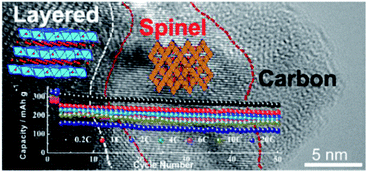 | ||
| Fig. 11 A Li-rich LSC heterostructured cathode material, comprised of a Li-rich layered core, a spinel interlayer, and a carbon nanocoating. Reproduced with permission.158 | ||
Chen et al.159 proposed and constructed a spinel-structure skin and ferric oxide islands on the surface of layered Li-rich cathode materials through a facile wet chemical method. The modified sample displayed a high discharge capacity of 166 mA h g−1 at 1.25 A g−1, and more stable capacity retention of 84.0% after 50 cycles at C/10, in contrast to 60.6% for pristine material. Their surface modification strategy, combining with the advantages of spinel structure and chemically inert ferric oxide nanoparticles, realized the layered Li-rich cathodes with surface construction of fast ion diffusing capability as well as robust electrolyte corroding durability. This design is able to modify the subsurface structure and surface environment of layered lithium–metal oxides particles, simultaneously.
3.4 Surface modification for high voltage spinel cathodes
Spinel LiMn2−xMxO4 (M = Ni, Cr, Cu, Fe, and Co) materials generally have a high voltage plateau at >4.5 V and deliver a high capacity in the range of 130–150 mA h g−1. However, these materials suffer from structural instability, electrolyte decomposition, dissolution of Mn and Ni, and Jahn–Teller distortion, particularly under high voltage and elevated temperatures. Previous reports on surface coatings, such as ZnO,160 TiO2,161 SiO2,162 Y2O3,163 CuO,164 and V2O5,165 have indicated the improvement over the electrochemical performance of the cathode materials. Unfortunately, the high-voltage spinels still undergo poor rate performances, large capacity fade, or discharge voltage decay because of low conductivity or stability issue of these oxide materials. Efficient route needs be designed to further enhance their cyclic properties for practical applications of the high-voltage spinel materials in LIBs.Recently, Gao et al.166 explored conductive PPy-coated LiNi0.5Mn1.5O4 (LNMO) cathodes for LIBs, considering the electrical conductivity of PPy could reach a few tenths of S cm−1. They compared the cycling performances of bare LNMO and PPy-coated LNMO at 1C and 55 °C (Fig. 12a and b). The bare LNMO delivered a discharge capacity of 94.5 mA h g−1 and exhibited capacity retention of only 81.4% after 100 cycles. While the LNMO-5 wt% PPy still retained a reversible capacity of 105.2 mA h g−1, corresponding to a retention of 91% after 100 cycles. The CEs of all the cells with PPy coating could reach 92% after 5 cycles, while that for bare LNMO was only around 90%. They also demonstrated (Fig. 12c) that a uniform PPy coating on the surface of the LNMO could not only act as an ion-conductive layer, but also suppress the decomposition of Mn and Ni at elevated temperatures.
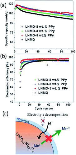 | ||
| Fig. 12 Cycling performance of LNMO, LNMO-3 wt% PPy, LNMO-5 wt%, and LNMO-8 wt% PPy at 1C and 55 °C: (a) specific capacity, and (b) CE. (c) Illustration of how the PPy layer acts as a conductive and protective layer to suppress the dissolution of Mn, as well as the unwanted electrolyte decomposition at elevated temperature. Reproduced with permission.166 | ||
FeF3-coated LiMn2O4 materials were synthesized by chemical deposition method. The FeF3-coated LiMn2O4 electrodes displayed enhanced cycling stabilities compared with that of pristine LiMn2O4. Especially, the 5 wt% FeF3-coated LiMn2O4 achieved the capacity retentions of 68.2% after 200 cycles at 25 °C, and 61.5% after 100 cycles at 55 °C, which were much better than those of the pristine materials (49.8% and 40.2%). They explained the effect of FeF3 surface coating including: (1) preventing the dissolution of Mn ions; (2) suppressing the impedance increase in repeated cycling; and (3) improving thermal stability of electrode material.167 Similarly, Wu et al.168 modified spinel LNMO cathode material synthesized by a sol–gel method with thin AlF3 coatings through simple chemical deposition. The AlF3-coated LNMO materials displayed enhanced cycling stabilities. The 1 wt% AlF3-coated LNMO showed improved reversibility with capacity retention of 93.6% after 50 cycles, which was much higher than that of the pristine material (77.6%).
AlPO4-coated LNMO was prepared by a sol–gel method with citric acid.169 The thickness of the coated layers of LNMO/AlPO4 (1 wt%) was determined to be about 15 nm by AES with sputtering. It was found that the surface and charge-transfer resistances of the modified electrode (4.3 and 20.7 Ω) were much lower than those of the pristine sample (5.9 and 52.8 Ω), and the Li+ diffusion rate of the modified electrode was also significantly enhanced. As a result, AlPO4 could be employed as a coating material to improve the thermal stability and electrochemical performance of LNMO cathodes.
The Li2ZrO3-coated spherical spinel LiMn2O4 samples were synthesized via sol–gel method.170 It was found that the Li2ZrO3 coating uniformly deposited on the surface of the spherical spinel LiMn2O4 with a thickness of 3 nm. The electrochemical results indicated that the 3 wt% Li2ZrO3 coated LiMn2O4 sample possessed excellent cycling performance with 99.0% and 90.2% capacity retention after 100 cycles at 1C at 25 °C and 55 °C, compared to 89.9% and 58.0% of uncoated spinel LiMn2O4. It was demonstrated that Li2ZrO3 as a ceramic material not only had excellent stability and chemical inert towards HF erosion, but also the structure of Li2ZrO3 was compatible for Li+ transportation.
Spinel LiMn2O4 and multi-doped spinel LiMn1.9Co0.025Cr0.025Ni0.025Fe0.025O4 (LMCCNF) were synthesized by the glycine-nitrate method and coated with Li borosilicate (LBS) via the simple solution method in order to enhance the electrochemical performance at room temperature.171 Compared with the uncoated samples, the LBS-coated LMCCNF sample exhibited an improved cycling stability. The capacity losses in the first 70 cycles between 3.5 and 4.5 V decreased significantly from 25.4%, 16.1% to 11% for uncoated LiMn2O4, LMCCNF and LBS coated LiMn2O4, respectively. The LBS-coated LMCCNF showed 8.5% capacity loss of the initial discharge capacity.
A novel spinel cathode material with an average composition of LiMn1.912Ni0.072Co0.016O4, in which the LiMn2O4 core material was completely encapsulated by a stable spinel structure concentration-gradient shell (CGS), was successfully synthesized via co-precipitation process.172 This arterial consisted of a core of LiMn2O4 and a CGS with decreasing Mn concentration and increasing Ni and Co concentration toward the particle surface. It was found that the electrochemical properties of the LiMn1.912Ni0.072Co0.016O4 material were superior to those of the alone LiMn2O4 core material. Besides, the core-CGS LiMn1.912Ni0.072Co0.016O4 sample delivered a discharge capacity of 118 mA h g−1 between 3.0 and 4.4 V vs. Li+/Li with a retention of 96% over 200 cycles at 1C (148 mA g−1) and 55 °C. It could still deliver a high discharge capacity of over 110 mA h g−1 even at 5C.
3.5 Nanostructured films on sulfur based cathodes
World-wide attention has been gained to sulfur and metal sulfides as promising cathode materials for LIBs due to their high theoretical specific capacity (1672 mA h g−1 for S, and 1166 mA h g−1 for Li2S). However, there are two major disadvantages that limit practical applications of the S-based cathodes. One is associated with uncontrolled dissolution and loss of intermediate lithium polysulphide (Li2Sn, n = 4–8) species into the electrolyte, leading to fast capacity decay and low CE. The other one is the large volume change during charge–discharge process, leading to pulverization and inactivity of cathode materials and thus poor cycling life and rate capability. Typical strategy to address these challenges is to encapsulate S-based materials with electronically conductive carbon-based materials.173–176 Although such approaches have shown many progresses with improved electrochemical performance for the S-based electrodes, electrochemical reversibility and rate capacity of the modified S-based materials are still unsatisfactory. It is considered that the nonpolar nature of carbon-based materials leads to weak interaction with polar S-containing species,177 which greatly reduces their ability to bind and confine these species within the carbon-based shell during cycling. Therefore, there is an urgent need in new modification routes for S-based cathodes that can achieve both high conductivity and strong binding with S-based materials simultaneously.Recently, Seh et al.177 encapsulated Li2S cathodes by using 2D layered transition metal disulphides that possessed a combination of high conductivity and strong binding with Li2S/Li2Sn species. Using TiS2 with a thickness of ∼20 nm as an encapsulation material, the Li2S@TiS2 cathodes showed stable cycling performance at C/2 over 400 cycles. Relative to the initial specific capacity of 666 mA h gLi2S−1 (956 mA h g−1) at C/2, the cells retained 77% of their capacity after 400 cycles (i.e., a capacity decay of 0.058% per cycle). The average CE was 98%. Moreover, they also demonstrated a high specific capacity of 503 mA h gLi2S−1 at 4C as well as a high areal capacity of 3 mA h cm−2 under high mass-loading conditions (5.3 mgLi2S cm−2). The improvement of electrochemical performance should be related to the facts that TiS2 possessed high conductivity, and polar Ti–S groups could potentially interact strongly with Li2S/Li2Sn species. By using ZrS2 and VS2 as further examples, this work open up the new concept of using 2D layered transition metal disulphides as a general class of effective encapsulation materials for achieving high performance in Li2S cathodes.
In addition, Tan et al.178 reported a facile and novel method to prepare pyrite nano-FeS2 wrapped in an N-graphene framework (core–shell nano-FeS2@N-graphene). The N-doped graphene as shell had optimized electronic conductivity, which made the FeS2 nanoparticles possess more fast charge transfer channels. As a result, the cells with FeS2@N-graphene cathode exhibited a high specific energy (950 W h kg−1 at 0.1 A g−1), high specific power (543 W h kg−1 at 2 A g−1) than the commercial cathodes, as well as stable cycling performance (∼600 W h kg−1 at 0.75 kW g−1 after 400 cycles). Compared to the reported LiCoO2 (504 W h kg−1), LiNi0.5Co0.2Mn0.3O2 (530 W h kg−1 at 0.5 A g−1), LiFePO4 (450 W h kg−1 at 0.5 A g−1) and LiMn2O4, (390 W h kg−1 at 0.5 A g−1), the FeS2@N-graphene showed a potential cathode material for the next generation LIBs.
Li et al.179 developed a feasible strategy to deposit double-layered films containing conducting polymer of PPy and carbon nanofiber (CNF) on NiS to form high-performance free-standing LIB cathodes. Using the PPy–CNF hybrid films with a high NiS loading of 5.5 mg cm−2 as a cathode, they demonstrated a high discharge capacity of 635 mA h g−1 at 0.1 A g−1 and exceptional areal capacity of 3.03 mA h cm−2 at 0.7 mA cm−2 with long cycling life over 700 cycles. It was emphasized that PPy coating maintained the structural integrity and accommodated volumetric change of NiS upon cycling, and also enhanced electronic conduction, while CNF film provided a well mechanical and effectively electrical interconnection in the entire electrode. This work provides new avenues for further improvement by conductive hybrid coatings on NiS cathodes to yield high capacity and long-term stability. This promising design and concept can be extended to other high-capacity cathodes with high volumetric expansion, such as S and Li2S.
Zhu et al.180 fabricated an FeS2@carbon fiber electrode consisting of FeS2 nanoparticles embedded into carbon fibers by electrospinning, the whole FeS2@carbon fiber electrode was then coated with a thin layer of Al2O3 (∼5 nm) by using ALD. It was observed from Fig. 13a that the Al2O3-coated FeS2@carbon fiber electrode presented great electrochemical performance in the voltage range of between 1 and 3 V (vs. Li+/Li). The discharge energy density of the Al2O3-coated FeS2@carbon fiber electrode initially reached 1000 W h kg−1 at electrode level and ∼1300 W h kg−1 at material level with a retention of 840 W h kgelectrode−1 (∼1110 W h kgFeS2−1) after 100 cycles. They also illustrated the mechanisms for the enhanced cycling stability by Al2O3 coating (Fig. 13b). First, it could improve the integrity of electrodes, which should be attributed to the mechanical protection provided by the conformal Al2O3 coating. Second, the Al2O3 coating could serve as an artificial barrier to restrain the lithium polysulfides dissolution and mitigate the shuttle effects. Third, upon electrochemical cycling, AlF3 and LiAlO2 with enhanced ionic conductivity would be formed on the top of Al2O3 coating layer due to the interactions between electrolyte salt and Al2O3.
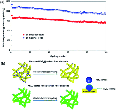 | ||
| Fig. 13 (a) Cycling stability at material level (W h kgFeS2−1) and electrode level (W h kgFeS2 electorde−1) for Al2O3-coated FeS2@carbon fiber electrode; (b) illustration of mechanisms for the enhanced cycling stability by Al2O3 coating. Reproduced with permission from ref. 180, copyright 2016, American Chemical Society. | ||
4. New materials and chemistry for Li-based batteries
Issues such as cost, safety and energy density should be addressed for conventional rechargeable LIBs when they are considered for electric vehicle and smart grid applications. New demonstration using low material cost, facile battery manufacture and flexible cell design offers possibilities that are not easily accessible for traditional materials and setup. This section discusses the recent development in organic electrode materials, novel electrolyte chemistry (high voltage aqueous electrolytes, and dual-ion electrolytes), new electrodes and cell configurations (symmetric electrodes, and semi-solid flow suspension) for Li-based rechargeable batteries. LIBs use typically static transition metal-based inorganic solid state electrode materials and organic solvent-based electrolyte to achieve high operation voltage and broad electrochemical window, respectively. Affordable green energy storage technologies using alternative materials/electrolytes, versatile battery structure are desirable for practical applications.4.1 Organic active materials
Rechargeable batteries with organic electrode materials are promising in terms of resource availability, cost and sustainability. Physiochemical and electrochemical properties of organic compounds can be altered by modifying their structures. Comprehensive summaries of organic electrode materials for energy storage have been overviewed elsewhere.181,182 Organic electrode materials can be classified as: organosulfur, radical and carbonyl compounds, polymers and layered materials etc. (Fig. 14a).183 Many organic materials show high practical capacities beyond 300 mA h g−1.184 For instance, benzoquinone has theoretical capacity of 496 mA h g−1, and can be operated at 2.8 V with a corresponding energy density up to 1400 W h kg−1, compared to about 400–500 W h kg−1 for the common inorganic LiCoO2 and LiFePO4. A carbonyl compound calix[4]quinone (C28H16O8, theoretical capacity 446 mA h g−1) has an initial capacity of about 422 mA h g−1 (Fig. 14b), and can still deliver a capacity of about 380 mA h g−1 after 100 cycles at C/5 using a gel polymer electrolyte.184 Active organic material such as Li4C6O6 containing C![[double bond, length as m-dash]](https://www.rsc.org/images/entities/char_e001.gif) O functionalities enables a multiple-electron transfer reaction in a symmetric cell Li2C6O6/Li6C6O6 with a good cyclability of about 200 mA h g−1 (Fig. 14c).185
O functionalities enables a multiple-electron transfer reaction in a symmetric cell Li2C6O6/Li6C6O6 with a good cyclability of about 200 mA h g−1 (Fig. 14c).185
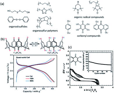 | ||
| Fig. 14 (a) Selected samples of organic electrode materials for LIBs. Reproduced with permission from ref. 183, copyright 2012, John Wiley and Sons. (b) A 8Li+/8e− reaction of a high capacity carbonyl compound calix[4]quinone (C28H16O8) and its voltage profile at C/5. Reproduced with permission from ref. 184, copyright 2013, John Wiley and Sons. (c) Structure and voltage profile of a lithium salt of tetrahydroxybenzoquinone in a symmetric configuration cycled between Li2C6O6 and Li6C6O6 at a rate of 1 Li+/10 h. Reproduced with permission from ref. 185, copyright 2009, American Chemical Society. | ||
Recently, an all-organic rechargeable battery with aqueous electrolyte with a high charge cutoff voltage of 2.1 V has been reported.186 An aqueous electrolyte containing lithium bis(trifluoromethanesulfonyl)imide (LiTFSI) with a concentration of 21 molarity allows a high redox potential of polytriphenylamine cathode (Fig. 15a), and a low negative potential of 1,4,5,8-naphthalenetetracarboxylic dianhydride-derived polyimide anode (Fig. 15b), without causing unwanted oxygen evolution (between 0.9 and 1.1 V vs. SCE) and hydrogen evolution reactions. A full cell test from 0.05 to 2.1 V showed a discharge capacity of 105 mA h g−1 at 0.5 A g−1, and 74 mA h g−1 at 10 A g−1, respectively. Over 700 cycles, the full cell exhibits stable cycling and a CE of about 100%. The application of aqueous electrolyte for high voltage operation will be further discussed in the next section.
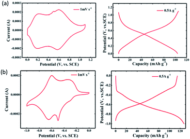 | ||
| Fig. 15 CV and charge/discharge curves (0.5 A g−1) for (a) polytriphenylamine cathode, (b) 1,4,5,8-naphthalenetetracarboxylic dianhydride-derived polyimide anode. Reproduced with permission from ref. 186, copyright 2017, John Wiley and Sons. | ||
4.2 Application of traditional electrode materials in aqueous electrolytes
Conventionally, organic solvents are used for Li-ion batteries with broad electrochemical window and enable high-voltage electrodes. In contrast to the conventional organic carbonate electrolytes, recent efforts to develop high-voltage aqueous electrolytes open new opportunity for safe and low-cost operation.187,188 Concentrated aqueous electrolyte of LiTFSI enables an electrochemical window of about 3 V, and an aqueous LiMn2O4/Mo6S8 cell to be operated at about 2 V with stable cycling performance (capacity retention 68% with 1000 cycles at 4.5C, 78% with 100 cycles at 0.15C) (Fig. 16a).187 At highly concentrated electrolytes, the onset of oxygen evolution reaction was shifted to higher potential and the inner Helmholtz layer of the electrode is almost only covered by the TFSI− anions.189 The hydrogen and oxygen evolution reactions are largely inhibited. In addition, aqueous electrolytes have high ionic conductivity. The mass transport limitations of organic electrolytes can be alleviated. Accordingly, thicker electrode fabrication and fast charging/discharging are expected. Gordon et al. has demonstrated a salt concentration-dependent lithiation potential of LiFePO4 (Fig. 16b), and a good cyclability of LiFePO4 in saturated LiNO3 aqueous solutions over 500 cycles (Fig. 16c).190 Higher salt concentration leads to higher lithiation potential and improved cycling stability. It also alleviated electrolyte depletion at high current densities.191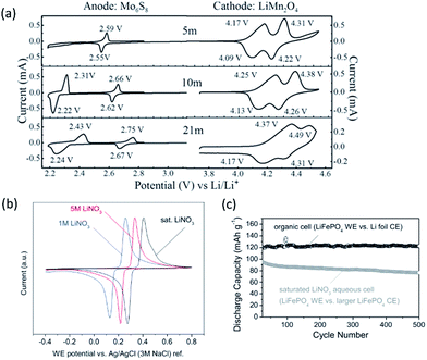 | ||
| Fig. 16 (a) CV response (0.1 mV s−1) of active materials LiMn2O4 and Mo6S8 in the concentrated LiTFSI/H2O electrolytes with different molality (m). Reproduced with permission from ref. 187, copyright 2015, The American Association for the Advancement of Science. (b) CV (0.3 mV s−1) of LiFePO4 electrodes in aqueous LiNO3 solutions of varying molarity, and (c) discharge capacities (at 1.1C rate) of LiFePO4 in aqueous (partially delithiated LiFePO4 as counter electrode) and organic (1 M LiPF6 in FEC/EMC, Li foil as counter electrode) electrolytes. Reproduced with permission from ref. 190, copyright 2015, John Wiley and Sons. | ||
4.3 Dual-ion batteries
Graphite can act as a redox-amphoteric host for intercalating anions and cations, yielding acceptor-type and donor-type intercalated graphite, respectively. In contrast to conventional rocking-chair LIBs, wherein Li+ ions are shuttled between the anode and cathode, the dual-ion batteries (also named as dual-graphite batteries, dual-carbon batteries) work through a simultaneous uptake of cations (for instance Li+) and anions (for instance TFSI−) from the electrolyte (for instance LiTFSI) into graphite anode and graphite cathode during charge, and a reversible release of both ions into the electrolyte during discharge (as schematically shown in Fig. 17a).192,193 In addition, dual-ion batteries are cost-effective and can be operated with higher voltage (for instance about 5 V) without safety issues. Over cycling, a continuous change in the salt concentration in electrolyte occurs, leading to a variation of ionic conductivity. The success of such dual-ion batteries relies on the anion intercalation chemistry and formation of stable SEI.192 Numerous anion intercalation guests have been studied, including fluorinated anions (BF4−, PF6−), oxo-complexes (SO4−, NO3−, ClO4−), chlorocomplex anions (GaCl4−, AlCl4−) and large anions such as bis(fluorosulfonyl)imide (FSI−) and TFSI−.194 The high intercalation potential of anions into graphite (typically beyond 4.4 V vs. Li+/Li, Fig. 17b)193 may cause oxidative decomposition of conventional carbonate solvents. The reversible capacity and CE depend largely on the character of anions (such as concentration, anion size, solvation with supporting solvents), the feature of carbon-based materials and the cycling voltage range.195,196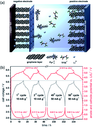 | ||
| Fig. 17 (a) Schematic illustration of a dual-ion battery using graphite as both cathode and anode, with the formation of a stable SEI layer at the negative graphite electrode. (b) Cathode potential, anode potential (red curves) and cell voltage (dotted black curve) profiles. Reprinted with permission.193 | ||
Recently, organic intercalation materials to host anions have been demonstrated,197,198 which pave the way for developing new low cost Li-based organic rechargeable dual-ion batteries. Organic dilithium 2,5-(dianilino)terephthalate (Li2DAnT) shows reversible anion intercalation behavior (Fig. 18a).197 Different voltage plateau profiles have been observed, depending on the type and size (ClO4− < PF6− < TFSI−) of anions. The smallest ClO4− gives rise to the lowest voltage polarization, suggesting a lower level structural variation when accommodating smaller anion in the organic host. The electrochemical incorporation of ClO4− anions has also been demonstrated using a porous-honeycomb organic framework (Fig. 18b and c).198 Fast ion transport and accordingly high rate capability can be achieved in such electrolyte-filled porous host structure. The capacity retention is about 60% by increasing the current density from 0.01 A g−1 (200 mA h g−1) to 0.1 A g−1 (120 mA h g−1). At 1 A g−1, high capacity retention of about 80% was observed over 7000 cycles.
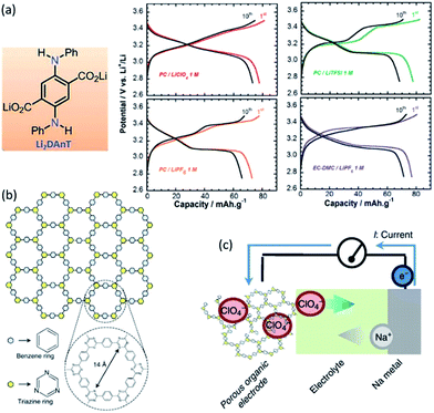 | ||
| Fig. 18 (a) Structure of Li2DAnT and voltage profiles of Li2DAnT when hosting different anions.197 (b) Porous organic anion host of having a honeycomb structure with a pore diameter of 1.4 nm, and (c) discharging process with ClO4− anions move out from the organic host. Reproduced with permission from ref. 198, copyright 2013, Nature Publishing Group. | ||
4.4 Symmetric electrodes
Besides graphite, many other materials can also be used as both cathode and anode in a symmetric battery system,199 relying on the fact that an identical electrode material can work at different potential ranges (Fig. 19a).200–202 Fig. 19b shows that for LiVPO4F, V4+/V3+ and V3+/V2+ redox reactions can occur at about 4.3 and 1.8 V, respectively, allowing a cell voltage of 2.4 V in a symmetric LIB.202 Li-based batteries with symmetric electrodes have merits of reduced manufacture cost, simple process, improved safety and ability of charging in both directions. Such batteries are expected to be able to tolerate large volume variation during (de)lithiation. Volume expansion from one side of the cell can be buffered from the volume shrinkage in the other side. Table 2 summarizes several electrode materials that can be used in symmetric rechargeable batteries.202–208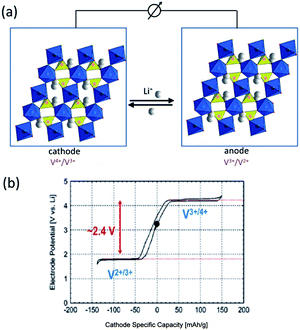 | ||
| Fig. 19 (a) Schematic illustration of a symmetric LIB with two redox couples of V4+/V3+ and V3+/V2+ in the LiVPO4F. Reproduced with permission from ref. 201, copyright 2011, American Chemical Society. (b) (De)lithiation reactions for a Li/LiVPO4F cell from 1.6 to 4.4 V showing two potential steps with a gap of about 2.4 V. Reproduced with permission from ref. 202, copyright 2013, American Chemical Society. | ||
| Symmetric electrodes | Positive electrode | Negative electrode | Ref. |
|---|---|---|---|
| LiMn2O4 | Mn4+/Mn3+ at 0.8 V vs. Ag/AgCl | Mn3+/Mn2+ at −0.3 V vs. Ag/AgCl | 203 |
| Li3V2(PO4)3 | V4+/V3+ at 4 V vs. Li+/Li | V3+/V2+ at 2 V vs. Li+/Li | 204 |
| LiVPO4F | V4+/V3+ at 4.2 V vs. Li+/Li | V3+/V2+ at 1.8 V vs. Li+/Li | 202 and 205 |
| Na1.16V3O8 | V4+/V3+ at 0.5 V vs. SCE | V3+/V2+ at −0.5 V vs. SCE | 206 |
| Na0.8Ni0.4Ti0.6O2 | Ni4+/Ni2+ at 3.5 V vs. Na+/Na | Ti4+/Ti3+ at 0.7 V vs. Na+/Na | 207 |
| Tetrasodium salt of 2,5-dihydroxyterephthalic acid (Na4C8H2O6) | Na2C8H2O6/Na4C8H2O6 at 2.3 V | Na4C8H2O6/Na6C8H2O6 at 0.3 V | 208 |
Symmetric cells are well-suited for studying the cycling reactions between electrode materials and electrolyte,209 and the degradation mechanism.210 Symmetric electrodes have also been assembled and demonstrated in supercapacitors,211 fuel cells,212 and in redox flow batteries with the attempt to avoid cross-contamination of active species.213–216
4.5 Semi-solid Li-flow batteries
Although significant advances in electrochemical energy storage devices, development of low-cost and high energy density system remains a challenge, especially for medium- and large-scale applications. Nowadays, many flow-assisted electrochemical systems based on different active materials are considered as an alternative route toward scalable and versatile energy storage. For such system, active electrolytes (soluble solutions or solid suspensions) are stored in two external individual tanks and circulated through the electrochemical cell to achieve a full redox reaction.217 For the conventional redox flow batteries, the solubility of active species in both the catholyte and anolyte is normally less than 2 M, which limits the volumetric energy density (typically below 30 W h L−1).218In 2011, a new concept of semi-solid lithium flow battery was first introduced by Chiang et al.219 as a way to utilize flowable intercalation materials as active suspension for enhanced energy storage (Fig. 20a). A high energy density of 397 W h L−1 has been achieved for a semi-solid LiCoO2/Li4Ti5O12 battery. Such system combines the advantages of both lithium-ion batteries with high energy-dense materials, and redox flow batteries with large design flexibility. The electron transfer between the active suspension materials and the current collector occurs through the formation of a percolation network among the agglomerated active solid materials and conductive carbon additives. A high volumetric capacity of 550 A h Lcatholyte−1 (corresponding to 580 W h Lcatholyte+Li−1) has been achieved with high CE (>95%) for a redox flow battery with multiple redox couples of I3−/I− and S/S2−.220
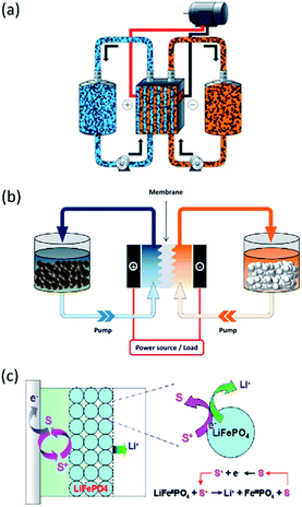 | ||
| Fig. 20 (a) Schematics of a semi-solid redox flow battery. Reproduced with permission from ref. 219, copyright 2011, John Wiley and Sons. (b) Illustration of a redox flow battery with statically stored solid active compounds in the tanks, and redox shuttle molecules circulating through the cell.221 (c) Working principle of reactions between the statically stored solid LiFePO4 with the flowing redox shuttle molecule (S+/S).221 Reproduced with permission. | ||
For semi-solid Li-flow batteries, carbon additives are needed for facilitating the electron transfer between the current collector and active solid particles (typically with low electrical conductivity). High content of carbon is necessary to form a percolating conductive network, which however leads to increased viscosity of the suspension and high pressure drop through the flow field. Reaction rate drops due to reduced bulk diffusion. The full utilization of active materials in this case cannot be realized. A redox targeting concept has been developed by Wang et al.221,222 to achieve carbon-free operation with statically stored active solid particles (Fig. 20b). A redox shuttle molecule is added into the electrolyte to have electron transfer reaction on the current collector inside the cell, while having chemical (de)lithiation reaction of active solid materials in the external tank (Fig. 20c). High solid content up to about 10 M can be used, whereas a diluted concentration of shuttle molecule of only several mM is sufficient in such system.
The concept of redox flow lithium batteries has been further expanded to the applications of redox flow Li–O2 batteries,223,224 redox flow Li–S batteries.225–228 For the traditional Li–S batteries, the formation of soluble polysulfide species leads to detrimental self-discharge. However, such attributes can be utilized in flow battery systems. The successful development of such new systems relies on the progress of selection and modification of carbon-based electrode materials,229 electrocatalysts,230 electrolytes231,232 and membranes.233,234
5. Conclusions and perspective
Electrodes with the issues of low electron/ion conductivities, large structure variation, and poor interfacial stability with electrolytes during the charge–discharge process limit the practical application of LIBs. The significant development of nanomaterials employed in both cathode and anode of LIBs to boost the performance has been discussed. By rationally controlling the nanoarchitectures of Si-based anode materials and using novel carbon-based anode materials, steady and high capacity over long-term cycling has been demonstrated. Nanoscale cathode materials with stable frameworks and fast Li+ conductivities can be applied as protective surface layer to promote the cycling performance of other high-capacity cathode materials. With a concentration gradient of transition metals from the outer surface to inner bulk, high energy density lithium metal oxide-based cathode materials can reach a compromise between good thermal and interface stabilities, high capacity and high rate. To tackle with the sluggish kinetics and shuttle effects encountered in Li–S batteries, chemical binding and physical confinement are effective strategies to assure electric contact and to inhibit dissolution loss of active species, respectively. Accordingly, durable and high capacity cathode materials can be achieved.Parallel to the studies of electrodes themselves, intensive efforts have been also taken by applying a nanoscale coating through various strategies. Surface modifications of the electrode materials make it possible to tolerate volume change and suppress side reactions. Further extensive investigations in surface modifications are required: (1) a rational design of strong chemical bonding between bulk and coating; (2) a multifunctional coating (e.g. fabricated by layer/layer and hollow shell) is desirable to simultaneously meet requirements, including large capacity, good rate capability and cycling stability; (3) detailed fundamental investigations of surface coating mechanisms are still needed.
Efforts to develop new low-cost active electrode materials using multi-electron transfer organic compounds, safe systems with high-voltage aqueous electrolytes, versatile battery design including dual-ion configuration, symmetric electrodes, semi-solid electrodes and flexible operation with flow electrolytes may open new avenue for advanced energy storage technologies in the future.
Acknowledgements
H. Z. gratefully acknowledges the financial support from the National Natural Science Foundation of China (no. 21603272). C. M. and J. L. acknowledge the funding support from the U.S. Department of Energy (DOE) under contract DE-AC05-00OR22725, and the Office of Energy Efficiency and Renewable Energy (EERE) Vehicle Technologies Office (VTO) (Deputy Director: David Howell) Applied Battery Research subprogram (Program Manager: Peter Faguy). R. C. thanks the basic research funding from KIST Europe.References
- M. S. Whittingham, Chem. Rev., 2004, 104, 4271–4301 CrossRef CAS PubMed.
- K. Mitzushima, P. C. Jones, P. J. Wiseman and J. Goodenough, Mater. Res. Bull., 1980, 15, 783–789 CrossRef.
- A. K. Padhi, K. S. Nanjundaswamy and J. B. Goodenough, J. Electrochem. Soc., 1997, 144, 1188–1194 CrossRef CAS.
- G. E. Blomgren, J. Electrochem. Soc., 2017, 164, A5019–A5025 CrossRef CAS.
- J. B. Goodenough and K.-S. Park, J. Am. Chem. Soc., 2013, 135, 1167–1176 CrossRef CAS PubMed.
- R. Van Noorden, Nature, 2014, 507, 26–28 CrossRef CAS PubMed.
- D. Andre, S.-J. Kim, P. Lamp, S. F. Lux, F. Maglia, O. Paschos and B. Stiaszny, J. Mater. Chem. A, 2015, 3, 6709–6732 CAS.
- Y. Lyu, N. Zhao, E. Hu, R. Xiao, X. Yu, L. Gu, X.-Q. Yang and H. Li, Chem. Mater., 2015, 27, 5238–5252 CrossRef CAS.
- D. Mohanty, J. Li, D. P. Abraham, A. Huq, E. A. Payzant, D. L. Wood and C. Daniel, Chem. Mater., 2014, 26, 6272–6280 CrossRef CAS.
- M. S. Islam, R. Dominko, C. Masquelier, C. Sirisopanaporn, A. R. Armstrong and P. G. Bruce, J. Mater. Chem., 2011, 21, 9811–9818 RSC.
- R. Chen, S. Ren, M. Knapp, D. Wang, R. Witter, M. Fichtner and H. Hahn, Adv. Energy Mater., 2015, 5, 1401814 CrossRef.
- R. Chen, E. Maawad, M. Knapp, S. Ren, P. Beran, R. Witter and R. Hempelmann, RSC Adv., 2016, 6, 65112–65118 RSC.
- M. N. Obrovac and V. L. Chevrier, Chem. Rev., 2014, 114, 11444–11502 CrossRef CAS PubMed.
- R. Chen, R. Heinzmann, S. Mangold, V. S. K. Chakravadhanula, H. Hahn and S. Indris, J. Phys. Chem. C, 2013, 117, 884–893 CAS.
- G. Hernández, N. Casado, R. Coste, D. Shanmukaraj, L. Rubatat, M. Armand and D. Mecerreyes, RSC Adv., 2015, 5, 17096–17103 RSC.
- J. W. Choi and D. Aurbach, Nat. Rev. Mater., 2016, 1, 16013 CrossRef CAS.
- N. Yabuuchi, Chem. Lett., 2017, 46, 412–422 CrossRef CAS.
- J. Lu, Z. Chen, Z. Ma, F. Pan, L. A. Curtiss and K. Amine, Nat. Nanotechnol., 2016, 11, 1031–1038 CrossRef CAS PubMed.
- M. Okubo, Y. Mizuno, H. Yamada, J. Kim, E. Hosono, H. Zhou, T. Kudo and I. Honma, ACS Nano, 2010, 4, 741–752 CrossRef CAS PubMed.
- C. Lai, Y. Y. Dou, X. Li and X. P. Gao, J. Power Sources, 2010, 195, 3676–3679 CrossRef CAS.
- V. Augustyn, J. Come, M. A. Lowe, J. W. Kim, P.-L. Taberna, S. H. Tolbert, H. D. Abruña, P. Simon and B. Dunn, Nat. Mater., 2013, 12, 518–522 CrossRef CAS PubMed.
- L. Croguennec and M. R. Palacin, J. Am. Chem. Soc., 2015, 137, 3140–3156 CrossRef CAS PubMed.
- J. Li, B. L. Armstrong, J. Kiggans, C. Daniel and D. L. Wood, J. Electrochem. Soc., 2013, 160, A201–A206 CrossRef CAS.
- P. G. Bruce, B. Scrosati and J. M. Tarascon, Angew. Chem., Int. Ed., 2008, 47, 2930–2946 CrossRef CAS PubMed.
- J. Li, C. Daniel and D. Wood, J. Power Sources, 2011, 196, 2452–2460 CrossRef CAS.
- G. Hautier, A. Jain, T. Mueller, C. Moore, S. P. Ong and G. Ceder, Chem. Mater., 2013, 25, 2064–2074 CrossRef CAS.
- S. Goriparti, E. Miele, F. De Angelis, E. Di Fabrizio, R. Proietti Zaccaria and C. Capiglia, J. Power Sources, 2014, 257, 421–443 CrossRef CAS.
- T. Chen, Q. Zhang, J. Xu, J. Pan and Y.-T. Cheng, RSC Adv., 2016, 6, 29308–29313 RSC.
- S. J. An, J. Li, C. Daniel, H. M. Meyer III, S. E. Trask, B. J. Polzin and D. L. Wood III, ACS Appl. Mater. Interfaces, 2017, 9, 18799–18808 CAS.
- H. Li, X. Huang, L. Chen, Z. Wu and Y. Liang, Electrochem. Solid-State Lett., 1999, 2, 547–549 CrossRef CAS.
- H. Kim, M. Seo, M. H. Park and J. Cho, Angew. Chem., Int. Ed., 2010, 49, 2146–2149 CrossRef CAS PubMed.
- J. P. Maranchi, A. F. Hepp, A. G. Evans, N. T. Nuhfer and P. N. Kumta, J. Electrochem. Soc., 2006, 153, A1246 CrossRef CAS.
- L.-F. Cui, L. Hu, J. W. Choi and Y. Cui, ACS Nano, 2010, 4, 3671–3678 CrossRef CAS PubMed.
- C. K. Chan, H. Peng, G. Liu, K. McIlwrath, X. F. Zhang, R. A. Huggins and Y. Cui, Nat. Nanotechnol., 2008, 3, 31–35 CrossRef CAS PubMed.
- T. Song, J. Xia, J. H. Lee, D. H. Lee, M. S. Kwon, J. M. Choi, J. Wu, S. K. Doo, H. Chang, W. I. Park, D. S. Zang, H. Kim, Y. Huang, K. C. Hwang, J. A. Rogers and U. Paik, Nano Lett., 2010, 10, 1710–1716 CrossRef CAS PubMed.
- K. McCormac, I. Byrd, R. Brannen, B. Seymour, J. Li and J. Wu, Phys. Status Solidi A, 2015, 212, 877–881 CrossRef CAS.
- C. K. Chan, R. N. Patel, M. J. O'Connell, B. A. Korgel and Y. Cui, ACS Nano, 2010, 4, 1443–1450 CrossRef CAS PubMed.
- M.-H. Park, M. G. Kim, J. Joo, K. Kim, J. Kim, S. Ahn, Y. Cui and J. Cho, Nano Lett., 2009, 9, 3844–3847 CrossRef CAS PubMed.
- H. Wu, G. Chan, J. W. Choi, I. Ryu, Y. Yao, M. T. McDowell, S. W. Lee, A. Jackson, Y. Yang, L. Hu and Y. Cui, Nat. Nanotechnol., 2012, 7, 310–315 CrossRef CAS PubMed.
- A. Magasinski, P. Dixon, B. Hertzberg, A. Kvit, J. Ayala and G. Yushin, Nat. Mater., 2010, 9, 353–358 CrossRef CAS PubMed.
- Y. Yao, M. T. McDowell, I. Ryu, H. Wu, N. Liu, L. Hu, W. D. Nix and Y. Cui, Nano Lett., 2011, 11, 2949–2954 CrossRef CAS PubMed.
- H. Ma, F. Cheng, J. Y. Chen, J. Z. Zhao, C. S. Li, Z. L. Tao and J. Liang, Adv. Mater., 2007, 19, 4067–4070 CrossRef CAS.
- H. Kim, B. Han, J. Choo and J. Cho, Angew. Chem., Int. Ed., 2008, 47, 10151–10154 CrossRef CAS PubMed.
- D. Chen, X. Mei, G. Ji, M. Lu, J. Xie, J. Lu and J. Y. Lee, Angew. Chem., Int. Ed., 2012, 51, 2409–2413 CrossRef CAS PubMed.
- X. Li, C. Yan, J. Wang, A. Graff, S. L. Schweizer, A. Sprafke, O. G. Schmidt and R. B. Wehrspohn, Adv. Energy Mater., 2015, 5, 1401556 CrossRef.
- S. Li, J. Niu, Y. C. Zhao, K. P. So, C. Wang, C. A. Wang and J. Li, Nat. Commun., 2015, 6, 7872 CrossRef CAS PubMed.
- H. Zhang, X. Zhong, J. C. Shaw, L. Liu, Y. Huang and X. Duan, Energy Environ. Sci., 2013, 6, 2621–2625 CAS.
- U. Kasavajjula, C. Wang and A. J. Appleby, J. Power Sources, 2007, 163, 1003–1039 CrossRef CAS.
- H.-T. Kwon, C. K. Lee, K.-J. Jeon and C.-M. Park, ACS Nano, 2016, 10, 5701–5709 CrossRef CAS PubMed.
- Y. Liu, R. Ma, Y. He, M. Gao and H. Pan, Adv. Funct. Mater., 2014, 24, 3944–3952 CrossRef CAS.
- G. Chen, L. Yan, H. Luo and S. Guo, Adv. Mater., 2016, 28, 7580–7602 CrossRef CAS PubMed.
- J. Yang, X.-Y. Zhou, J. Li, Y.-L. Zou and J.-J. Tang, Mater. Chem. Phys., 2012, 135, 445–450 CrossRef CAS.
- J. Sun, H. Liu, X. Chen, D. G. Evans, W. Yang and X. Duan, Adv. Mater., 2013, 25, 1125–1130 CrossRef CAS PubMed.
- Z. L. Yu, S. Xin, Y. You, L. Yu, Y. Lin, D. W. Xu, C. Qiao, Z. H. Huang, N. Yang, S. H. Yu and J. B. Goodenough, J. Am. Chem. Soc., 2016, 138, 14915–14922 CrossRef CAS PubMed.
- S. Iijima, Nature, 1991, 354, 56–58 CrossRef CAS.
- V. Meunier, J. Kephart, C. Roland and J. Bernholc, Phys. Rev. Lett., 2002, 88, 075506 CrossRef PubMed.
- C. M. Schauerman, M. J. Ganter, G. Gaustad, C. W. Babbitt, R. P. Raffaelle and B. J. Landi, J. Mater. Chem., 2012, 22, 12008 RSC.
- H. S. Oktaviano, K. Yamada and K. Waki, J. Mater. Chem., 2012, 22, 25167 RSC.
- H. Yoo, A. P. Tiwari, J. Lee, D. Kim, J. H. Park and H. Lee, Nanoscale, 2015, 7, 3404–3409 RSC.
- W.-J. Yu, L. Zhang, P.-X. Hou, F. Li, C. Liu and H.-M. Cheng, Adv. Energy Mater., 2016, 6, 1501755 CrossRef.
- J.-Y. Hwang, H. M. Kim, S.-K. Lee, J.-H. Lee, A. Abouimrane, M. A. Khaleel, I. Belharouak, A. Manthiram and Y.-K. Sun, Adv. Energy Mater., 2016, 6, 1501480 CrossRef.
- G. Huang, F. Zhang, X. Du, Y. Qin, D. Yin and L. Wang, ACS Nano, 2015, 9, 1592–1599 CrossRef CAS PubMed.
- R. A. Susantyoko, X. Wang, Q. Xiao, E. Fitzgerald and Q. Zhang, Carbon, 2014, 68, 619–627 CrossRef CAS.
- D. Pan, S. Wang, B. Zhao, M. Wu, H. Zhang, Y. Wang and Z. Jiao, Chem. Mater., 2009, 21, 3136–3142 CrossRef CAS.
- K. Chang and W. Chen, ACS Nano, 2011, 5, 4720–4728 CrossRef CAS PubMed.
- L. Jiang, B. Lin, X. Li, X. Song, H. Xia, L. Li and H. Zeng, ACS Appl. Mater. Interfaces, 2016, 8, 2680–2687 CAS.
- M. Srivastava, J. Singh, T. Kuila, R. K. Layek, N. H. Kim and J. H. Lee, Nanoscale, 2015, 7, 4820–4868 RSC.
- J. Wu, I. Byrd, C. Jin, J. Li, H. Chen, T. Camp, R. Bujol, A. Sharma and H. Zhang, ChemElectroChem, 2017, 4, 1181–1189 CrossRef CAS.
- B. Kang and G. Ceder, Nature, 2009, 458, 190–193 CrossRef CAS PubMed.
- R. Malik, F. Zhou and G. Ceder, Nat. Mater., 2011, 10, 587–590 CrossRef CAS PubMed.
- H. Liu, F. C. Strobridge, O. J. Borkiewicz, K. M. Wiaderek, K. W. Chapman, P. J. Chupas and C. P. Grey, Science, 2014, 344, 1252817 CrossRef PubMed.
- J. Lim, Y. Li, D. H. Alsem, H. So, S. C. Lee, P. Bai, D. A. Cogswell, X. Liu, N. Jin, Y.-s. Yu, N. J. Salmon, D. A. Shapiro, M. Z. Bazant, T. Tyliszczak and W. C. Chueh, Science, 2016, 353, 566 CrossRef CAS PubMed.
- F. Boucher, J. Gaubicher, M. Cuisinier, D. Guyomard and P. Moreau, J. Am. Chem. Soc., 2014, 136, 9144–9157 CrossRef CAS PubMed.
- Z. Wu, S. Ji, T. Liu, Y. Duan, S. Xiao, Y. Lin, K. Xu and F. Pan, Nano Lett., 2016, 16, 6357–6363 CrossRef CAS PubMed.
- Y. K. Sun, Z. Chen, H. J. Noh, D. J. Lee, H. G. Jung, Y. Ren, S. Wang, C. S. Yoon, S. T. Myung and K. Amine, Nat. Mater., 2012, 11, 942–947 CrossRef CAS PubMed.
- J. H. Lee, C. S. Yoon, J.-Y. Hwang, S.-J. Kim, F. Maglia, P. Lamp, S.-T. Myung and Y.-K. Sun, Energy Environ. Sci., 2016, 9, 2152–2158 CAS.
- F. Jiao, K. M. Shaju and P. G. Bruce, Angew. Chem., Int. Ed., 2005, 44, 6550–6553 CrossRef CAS PubMed.
- Y. Zhou and H. Li, J. Mater. Chem., 2002, 12, 681–686 RSC.
- P. G. Bruce, S. A. Freunberger, L. J. Hardwick and J. M. Tarascon, Nat. Mater., 2011, 11, 19–29 CrossRef PubMed.
- X. Liu, J.-Q. Huang, Q. Zhang and L. Mai, Adv. Mater., 2017, 29, 1601759 CrossRef PubMed.
- M. Wild, L. O'Neill, T. Zhang, R. Purkayastha, G. Minton, M. Marinescu and G. J. Offer, Energy Environ. Sci., 2015, 8, 3477–3494 CAS.
- G. L. Xu, Y. F. Xu, J. C. Fang, X. X. Peng, F. Fu, L. Huang, J. T. Li and S. G. Sun, ACS Appl. Mater. Interfaces, 2013, 5, 10782–10793 CAS.
- G. Li, J. Sun, W. Hou, S. Jiang, Y. Huang and J. Geng, Nat. Commun., 2016, 7, 10601 CrossRef CAS PubMed.
- M. Q. Zhao, H. J. Peng, G. L. Tian, Q. Zhang, J. Q. Huang, X. B. Cheng, C. Tang and F. Wei, Adv. Mater., 2014, 26, 7051–7058 CrossRef CAS PubMed.
- J. S. Lee, W. Kim, J. Jang and A. Manthiram, Adv. Energy Mater., 2017, 5, 1601943 CrossRef.
- G. Zheng, Q. Zhang, J. J. Cha, Y. Yang, W. Li, Z. W. She and Y. Cui, Nano Lett., 2013, 13, 1265–1270 CrossRef CAS PubMed.
- J. Song, M. L. Gordin, T. Xu, S. Chen, Z. Yu, H. Sohn, J. Lu, Y. Ren, Y. Duan and D. Wang, Angew. Chem., Int. Ed., 2015, 54, 4325–4329 CrossRef CAS PubMed.
- L. Fei, X. Li, W. Bi, Z. Zhuo, W. Wei, L. Sun, W. Lu, X. Wu, K. Xie, C. Wu, H. L. Chan and Y. Wang, Adv. Mater., 2015, 27, 5936–5942 CrossRef CAS PubMed.
- X. Ji, S. Evers, R. Black and L. F. Nazar, Nat. Commun., 2011, 2, 325 CrossRef PubMed.
- W. Miao, C. Zhang, Y. Cai, Y. Zhang and H. Lu, Analyst, 2016, 141, 2435–2440 RSC.
- X. Liang and L. F. Nazar, ACS Nano, 2016, 10, 4192–4198 CrossRef CAS PubMed.
- Z. Li, J. Zhang and X. W. Lou, Angew. Chem., Int. Ed., 2015, 54, 12886–12890 CrossRef CAS PubMed.
- S. Evers, T. Yim and L. F. Nazar, J. Phys. Chem. C, 2012, 116, 19653–19658 CAS.
- Z. Wei Seh, W. Li, J. J. Cha, G. Zheng, Y. Yang, M. T. McDowell, P. C. Hsu and Y. Cui, Nat. Commun., 2013, 4, 1331 CrossRef PubMed.
- C. Mao, F. Zuo, Y. Hou, X. Bu and P. Feng, Angew. Chem., Int. Ed., 2014, 53, 10485–10489 CrossRef CAS PubMed.
- Z. Liang, G. Zheng, W. Li, Z. W. Seh, H. Yao, K. Yan, D. Kong and Y. Cui, ACS Nano, 2014, 8, 5249–5256 CrossRef CAS PubMed.
- X. Tao, J. Wang, Z. Ying, Q. Cai, G. Zheng, Y. Gan, H. Huang, Y. Xia, C. Liang, W. Zhang and Y. Cui, Nano Lett., 2014, 14, 5288–5294 CrossRef CAS PubMed.
- Q. Pang, D. Kundu, M. Cuisinier and L. F. Nazar, Nat. Commun., 2014, 5, 4759 CrossRef CAS PubMed.
- Z. W. Seh, J. H. Yu, W. Li, P. C. Hsu, H. Wang, Y. Sun, H. Yao, Q. Zhang and Y. Cui, Nat. Commun., 2014, 5, 5017 CrossRef CAS PubMed.
- L. Ma, S. Wei, H. L. Zhuang, K. E. Hendrickson, R. G. Hennig and L. A. Archer, J. Mater. Chem. A, 2015, 3, 19857–19866 CAS.
- Q. Pang, D. Kundu and L. F. Nazar, Mater. Horiz., 2016, 3, 130–136 RSC.
- Z. Yuan, H. J. Peng, T. Z. Hou, J. Q. Huang, C. M. Chen, D. W. Wang, X. B. Cheng, F. Wei and Q. Zhang, Nano Lett., 2016, 16, 519–527 CrossRef CAS PubMed.
- L. Xu, Y. Hu, H. Zhang, H. Jiang and C. Li, ACS Sustainable Chem. Eng., 2016, 4, 4251–4255 CrossRef CAS.
- Y. Feng, Y. Zhang, Y. Wei, X. Song, Y. Fu and V. S. Battaglia, Phys. Chem. Chem. Phys., 2016, 18, 30630–30642 RSC.
- T. Lei, W. Chen, J. Huang, C. Yan, H. Sun, C. Wang, W. Zhang, Y. Li and J. Xiong, Adv. Energy Mater., 2017, 7, 1601843 CrossRef.
- K. X. Wang, X. H. Li and J. S. Chen, Adv. Mater., 2015, 27, 527–545 CrossRef CAS PubMed.
- X. Meng, X. Q. Yang and X. Sun, Adv. Mater., 2012, 24, 3589–3615 CrossRef CAS PubMed.
- Q. Wang, D.-A. Zhang, Q. Wang, J. Sun, L.-L. Xing and X.-Y. Xue, Electrochim. Acta, 2014, 146, 411–418 CrossRef CAS.
- C. Guan, X. Wang, Q. Zhang, Z. Fan, H. Zhang and H. J. Fan, Nano Lett., 2014, 14, 4852–4858 CrossRef CAS PubMed.
- J.-S. Kim, D. W. Kim, H. T. Jung and J. W. Choi, Chem. Mater., 2015, 27, 2780–2787 CrossRef CAS.
- I. V. Ferrari, M. Braglia, T. Djenizian, P. Knauth and M. L. Di Vona, J. Power Sources, 2017, 353, 95–103 CrossRef CAS.
- N. Kamaya, K. Homma, Y. Yamakawa, M. Hirayama, R. Kanno, M. Yonemura, T. Kamiyama, Y. Kato, S. Hama, K. Kawamoto and A. Mitsui, Nat. Mater., 2011, 10, 682–686 CrossRef CAS PubMed.
- K. Yan, H.-W. Lee, T. Gao, G. Zheng, H. Yao, H. Wang, Z. Lu, Y. Zhou, Z. Liang, Z. Liu, S. Chu and Y. Cui, Nano Lett., 2014, 14, 6016–6022 CrossRef CAS PubMed.
- W. Liu, D. Lin, A. Pei and Y. Cui, J. Am. Chem. Soc., 2016, 138, 15443–15450 CrossRef CAS PubMed.
- W. Liu, W. Li, D. Zhuo, G. Zheng, Z. Lu, K. Liu and Y. Cui, ACS Cent. Sci., 2017, 3, 135–140 CrossRef CAS PubMed.
- H. Zhang, M. Yao and X. Liu, Composite anode of lithium-ion batteries, West Virginia University, Morgantown, WV, United States, 2014 Search PubMed.
- A. Magasinski, P. Dixon, B. Hertzberg, A. Kvit, J. Ayala and G. Yushin, Nat. Mater., 2010, 9, 353–358 CrossRef CAS PubMed.
- B. Fuchsbichler, C. Stangl, H. Kren, F. Uhlig and S. Koller, J. Power Sources, 2011, 196, 2889–2892 CrossRef CAS.
- J. Li, X. Xiao, Y.-T. Cheng and M. W. Verbrugge, J. Phys. Chem. Lett., 2013, 4, 3387–3391 CrossRef CAS.
- B. Zhu, N. Liu, M. McDowell, Y. Jin, Y. Cui and J. Zhu, Nano Energy, 2015, 13, 620–625 CrossRef CAS.
- W. Li, Y. Tang, W. Kang, Z. Zhang, X. Yang, Y. Zhu, W. Zhang and C.-S. Lee, Small, 2015, 11, 1345–1351 CrossRef CAS PubMed.
- X. Xiao, P. Lu and D. Ahn, Adv. Mater., 2011, 23, 3911–3915 CrossRef CAS PubMed.
- G. Liu, S. Xun, N. Vukmirovic, X. Song, P. Olalde-Velasco, H. Zheng, V. S. Battaglia, L. Wang and W. Yang, Adv. Mater., 2011, 23, 4679–4683 CrossRef CAS PubMed.
- J. Chang, X. Huang, G. Zhou, S. Cui, P. B. Hallac, J. Jiang, P. T. Hurley and J. Chen, Adv. Mater., 2014, 26, 758–764 CrossRef CAS PubMed.
- A. Kohandehghan, P. Kalisvaart, K. Cui, M. Kupsta, E. Memarzadeh and D. Mitlin, J. Mater. Chem. A, 2013, 1, 12850–12861 CAS.
- E. L. Memarzadeh, W. P. Kalisvaart, A. Kohandehghan, B. Zahiri, C. M. B. Holt and D. Mitlin, J. Mater. Chem., 2012, 22, 6655–6668 RSC.
- M. T. McDowell, S. Woo Lee, C. Wang and Y. Cui, Nano Energy, 2012, 1, 401–410 CrossRef CAS.
- G. Jeong, J. G. Kim, M. S. Park, M. Seo, S. M. Hwang, Y. U. Kim, Y. J. Kim, J. H. Kim and S. X. Dou, ACS Nano, 2014, 8, 2977–2985 CrossRef CAS PubMed.
- W. Luo, Y. Wang, L. Wang, W. Jiang, S.-L. Chou, S. X. Dou, H. K. Liu and J. Yang, ACS Nano, 2016, 10, 10524–10532 CrossRef CAS PubMed.
- J. Liu, Y. Wen, P. A. van Aken, J. Maier and Y. Yu, Nano Lett., 2014, 14, 6387–6392 CrossRef CAS PubMed.
- Y. Xu, H. Wang, R. Zhu, C. Liu, X. Wu and B. Zhang, Chem.–Asian J., 2013, 8, 1120–1127 CrossRef CAS PubMed.
- J. Liu, X. Xu, R. Hu, L. Yang and M. Zhu, Adv. Energy Mater., 2016, 6, 1600256 CrossRef.
- C. Wang, L. Yin, D. Xiang and Y. Qi, ACS Appl. Mater. Interfaces, 2012, 4, 1636–1642 CAS.
- C. Zhu, X. Xia, J. Liu, Z. Fan, D. Chao, H. Zhang and H. J. Fan, Nano Energy, 2014, 4, 105–112 CrossRef CAS.
- X. Hou, X. Wang, B. Liu, Q. Wang, Z. Wang, D. Chen and G. Shen, ChemElectroChem, 2014, 1, 108–115 CrossRef.
- J.-H. Jeun, K.-Y. Park, D.-H. Kim, W.-S. Kim, H.-C. Kim, B.-S. Lee, H. Kim, W.-R. Yu, K. Kang and S.-H. Hong, Nanoscale, 2013, 5, 8480–8483 RSC.
- G. Ji, B. Ding, Y. Ma and J. Y. Lee, Energy Technol., 2013, 1, 567–572 CrossRef CAS.
- J.-H. Lee, M.-H. Hon, Y.-W. Chung and I.-C. Leu, Appl. Phys. A, 2011, 102, 545–550 CrossRef CAS.
- B. Ahmed, M. Shahid, D. H. Nagaraju, D. H. Anjum, M. N. Hedhili and H. N. Alshareef, ACS Appl. Mater. Interfaces, 2015, 7, 13154–13163 CAS.
- Z. Xu, H. Wang, Z. Li, A. Kohandehghan, J. Ding, J. Chen, K. Cui and D. Mitlin, J. Phys. Chem. C, 2014, 118, 18387–18396 CAS.
- C.-F. Lin, M. Noked, A. C. Kozen, C. Liu, O. Zhao, K. Gregorczyk, L. Hu, S. B. Lee and G. W. Rubloff, ACS Nano, 2016, 10, 2693–2701 CrossRef CAS PubMed.
- D. Mohanty, J. Li, S. C. Nagpure, D. L. Wood and C. Daniel, MRS Energy & Sustainability, 2015, 2, E15 Search PubMed.
- D. Mohanty, A. Huq, E. A. Payzant, A. S. Sefat, J. Li, D. P. Abraham, D. L. Wood III and C. Daniel, Chem. Mater., 2013, 25, 4064–4070 CrossRef CAS.
- D. Mohanty, A. S. Sefat, J. Li, R. A. Meisner, A. J. Rondinone, E. A. Payzant, D. P. Abraham, D. L. Wood III and C. Daniel, Phys. Chem. Chem. Phys., 2013, 15, 19496–19509 RSC.
- X. Zhang, I. Belharouak, L. Li, Y. Lei, J. W. Elam, A. Nie, X. Chen, R. S. Yassar and R. L. Axelbaum, Adv. Energy Mater., 2013, 3, 1299–1307 CrossRef CAS.
- E. Zhao, X. Liu, H. Zhao, X. Xiao and Z. Hu, Chem. Commun., 2015, 51, 9093–9096 RSC.
- X. Zhang, S. Sun, Q. Wu, N. Wan, D. Pan and Y. Bai, J. Power Sources, 2015, 282, 378–384 CrossRef CAS.
- W. Yuan, H. Z. Zhang, Q. Liu, G. R. Li and X. P. Gao, Electrochim. Acta, 2014, 135, 199–207 CrossRef CAS.
- T. Zhao, S. Chen, R. Chen, L. Li, X. Zhang, M. Xie and F. Wu, ACS Appl. Mater. Interfaces, 2014, 6, 21711–21720 CAS.
- H. Liu, C. Chen, C. Du, X. He, G. Yin, B. Song, P. Zuo, X. Cheng, Y. Ma and Y. Gao, J. Mater. Chem. A, 2015, 3, 2634–2641 CAS.
- J. Liu, B. Reeja-Jayan and A. Manthiram, J. Phys. Chem. C, 2010, 114, 9528–9533 CAS.
- S. K. Martha, J. Nanda, Y. Kim, R. R. Unocic, S. Pannala and N. J. Dudney, J. Mater. Chem. A, 2013, 1, 5587–5595 CAS.
- J. Zhang, Z. Lei, J. Wang, Y. NuLi and J. Yang, ACS Appl. Mater. Interfaces, 2015, 7, 15821–15829 CAS.
- Q. Q. Qiao, H. Z. Zhang, G. R. Li, S. H. Ye, C. W. Wang and X. P. Gao, J. Mater. Chem. A, 2013, 1, 5262–5268 CAS.
- L. Guo, J. Li, T. Cao, H. Wang, N. Zhao, F. He, C. Shi, C. He and E. Liu, ACS Appl. Mater. Interfaces, 2016, 8, 24594–24602 CAS.
- H. Z. Zhang, Q. Q. Qiao, G. R. Li, S. H. Ye and X. P. Gao, J. Mater. Chem., 2012, 22, 13104–13109 RSC.
- F. Wu, N. Li, Y. Su, L. Zhang, L. Bao, J. Wang, L. Chen, Y. Zheng, L. Dai, J. Peng and S. Chen, Nano Lett., 2014, 14, 3550–3555 CrossRef CAS PubMed.
- Q. Xia, X. Zhao, M. Xu, Z. Ding, J. Liu, L. Chen, D. G. Ivey and W. Wei, J. Mater. Chem. A, 2015, 3, 3995–4003 CAS.
- S. Chen, Y. Zheng, Y. Lu, Y. Su, L. Bao, N. Li, Y. Li, J. Wang, R. Chen and F. Wu, ACS Appl. Mater. Interfaces, 2017, 9, 8669–8678 CAS.
- R. Alcántara, M. Jaraba, P. Lavela and J. L. Tirado, J. Electroanal. Chem., 2004, 566, 187–192 CrossRef.
- S. Tao, F. Kong, C. Wu, X. Su, T. Xiang, S. Chen, H. Hou, L. Zhang, Y. Fang, Z. Wang, W. Chu, B. Qian and L. Song, J. Alloys Compd., 2017, 705, 413–419 CrossRef CAS.
- Y. Fan, J. Wang, Z. Tang, W. He and J. Zhang, Electrochim. Acta, 2007, 52, 3870–3875 CrossRef CAS.
- B. Ju, X. Wang, C. Wu, Q. Wei, X. Yang, H. Shu and Y. Bai, J. Solid State Electrochem., 2014, 18, 115–123 CrossRef CAS.
- X. Li, W. Guo, Y. Liu, W. He and Z. Xiao, Electrochim. Acta, 2014, 116, 278–283 CrossRef CAS.
- J. Wang, S. Yao, W. Lin, B. Wu, X. He, J. Li and J. Zhao, J. Power Sources, 2015, 280, 114–124 CrossRef CAS.
- X.-W. Gao, Y.-F. Deng, D. Wexler, G.-H. Chen, S.-L. Chou, H.-K. Liu, Z.-C. Shi and J.-Z. Wang, J. Mater. Chem. A, 2015, 3, 404–411 CAS.
- S. Zhao, Y. Bai, Q. Chang, Y. Yang and W. Zhang, Electrochim. Acta, 2013, 108, 727–735 CrossRef CAS.
- Q. Wu, Y. Yin, S. Sun, X. Zhang, N. Wan and Y. Bai, Electrochim. Acta, 2015, 158, 73–80 CrossRef CAS.
- J. Y. Shi, C.-W. Yi and K. Kim, J. Power Sources, 2010, 195, 6860–6866 CrossRef CAS.
- X. Yi, X. Wang, B. Ju, H. Shu, W. Wen, R. Yu, D. Wang and X. Yang, Electrochim. Acta, 2014, 134, 143–149 CrossRef CAS.
- H. Şahan, M. N. Ateş, F. K. Dokan, A. Ülgen and Ş. Patat, Bull. Mater. Sci., 2015, 38, 141–149 CrossRef.
- W. Wen, S. Chen, Y. Fu, X. Wang and H. Shu, J. Power Sources, 2015, 274, 219–228 CrossRef CAS.
- N. Ding, Y. Lum, S. Chen, S. W. Chien, T. S. A. Hor, Z. Liu and Y. Zong, J. Mater. Chem. A, 2015, 3, 1853–1857 CAS.
- Z. W. Seh, H. Wang, N. Liu, G. Zheng, W. Li, H. Yao and Y. Cui, Chem. Sci., 2014, 5, 1396–1400 RSC.
- C. Zhang, H. B. Wu, Z. Guo and X. W. Lou, Electrochem. Commun., 2012, 20, 7–10 CrossRef CAS.
- T. Takeuchi, H. Sakaebe, H. Kageyama, H. Senoh, T. Sakai and K. Tatsumi, J. Power Sources, 2010, 195, 2928–2934 CrossRef CAS.
- Z. W. Seh, J. H. Yu, W. Li, P.-C. Hsu, H. Wang, Y. Sun, H. Yao, Q. Zhang and Y. Cui, Nat. Commun., 2014, 5, 5017 CrossRef CAS PubMed.
- R. Tan, J. Yang, J. Hu, K. Wang, Y. Zhao and F. Pan, Chem. Commun., 2016, 52, 986–989 RSC.
- X. Li, Y. Chen, J. Zou, X. Zeng, L. Zhou and H. Huang, J. Power Sources, 2016, 331, 360–365 CrossRef CAS.
- Y. Zhu, X. Fan, L. Suo, C. Luo, T. Gao and C. Wang, ACS Nano, 2016, 10, 1529–1538 CrossRef CAS PubMed.
- T. B. Schon, B. T. McAllister, P.-F. Li and D. S. Seferos, Chem. Soc. Rev., 2016, 45, 6345–6404 RSC.
- J. Xie and Q. Zhang, J. Mater. Chem. A, 2016, 4, 7091–7106 CAS.
- Y. Liang, Z. Tao and J. Chen, Adv. Energy Mater., 2012, 2, 742–769 CrossRef CAS.
- W. Huang, Z. Zhu, L. Wang, S. Wang, H. Li, Z. Tao, J. Shi, L. Guan and J. Chen, Angew. Chem., Int. Ed., 2013, 52, 9162–9166 CrossRef CAS PubMed.
- H. Chen, M. Armand, M. Courty, M. Jiang, C. P. Grey, F. Dolhem, J.-M. Tarascon and P. Poizot, J. Am. Chem. Soc., 2009, 131, 8984–8988 CrossRef CAS PubMed.
- X. Dong, H. Yu, Y. Ma, J. L. Bao, D. G. Truhlar, Y. Wang and Y. Xia, Chem.–Eur. J., 2017, 23, 2560–2565 CrossRef CAS PubMed.
- L. Suo, O. Borodin, T. Gao, M. Olguin, J. Ho, X. Fan, C. Luo, C. Wang and K. Xu, Science, 2015, 350, 938–943 CrossRef CAS PubMed.
- R. Chen and R. Hempelmann, Electrochem. Commun., 2016, 70, 56–59 CrossRef CAS.
- L. Coustan, G. Shul and D. Bélanger, Electrochem. Commun., 2017, 77, 89–92 CrossRef CAS.
- D. Gordon, M. Y. Wu, A. Ramanujapuram, J. Benson, J. T. Lee, A. Magasinski, N. Nitta, C. Huang and G. Yushin, Adv. Energy Mater., 2015, 6, 1501805 CrossRef.
- Z. Du, D. L. Wood, C. Daniel, S. Kalnaus and J. Li, J. Appl. Electrochem., 2017, 47, 405–415 CrossRef CAS.
- K. Xu, Chem. Rev., 2014, 114, 11503–11618 CrossRef CAS PubMed.
- S. Rothermel, P. Meister, G. Schmuelling, O. Fromm, H.-W. Meyer, S. Nowak, M. Winter and T. Placke, Energy Environ. Sci., 2014, 7, 3412–3423 CAS.
- T. Placke, O. Fromm, S. F. Lux, P. Bieker, S. Rothermel, H.-W. Meyer, S. Passerini and M. Winter, J. Electrochem. Soc., 2012, 159, A1755–A1765 CrossRef CAS.
- J. A. Read, A. V. Cresce, M. H. Ervin and K. Xu, Energy Environ. Sci., 2014, 7, 617–620 CAS.
- K. Beltrop, P. Meister, S. Klein, A. Heckmann, M. Grünebaum, H.-D. Wiemhöfer, M. Winter and T. Placke, Electrochim. Acta, 2016, 209, 44–55 CrossRef CAS.
- É. Deunf, P. Moreau, É. Quarez, D. Guyomard, F. Dolhem and P. Poizot, J. Mater. Chem. A, 2016, 4, 6131–6139 Search PubMed.
- K. Sakaushi, E. Hosono, G. Nickerl, T. Gemming, H. Zhou, S. Kaskel and J. Eckert, Nat. Commun., 2013, 4, 1485 CrossRef PubMed.
- L. Zhang, S. X. Dou, H. K. Liu, Y. Huang and X. Hu, Adv. Sci., 2016, 3, 1600115 CrossRef PubMed.
- Y. Zhang, H. Zhao and Y. Du, J. Mater. Chem. A, 2016, 4, 7155–7159 CAS.
- B. L. Ellis, T. N. Ramesh, L. J. M. Davis, G. R. Goward and L. F. Nazar, Chem. Mater., 2011, 23, 5138–5148 CrossRef CAS.
- C. Masquelier and L. Croguennec, Chem. Rev., 2013, 113, 6552–6591 CrossRef CAS PubMed.
- S.-I. Park, S. Okada and J.-i. Yamaki, J. Novel Carbon Res. Sci., 2011, 3, 27–31 Search PubMed.
- E. Kobayashi, L. S. Plashnitsa, T. Doi, S. Okada and J.-i. Yamaki, Electrochem. Commun., 2010, 12, 894–896 CrossRef CAS.
- L. S. Plashnitsa, E. Kobayashi, S. Okada and J.-i. Yamaki, Electrochim. Acta, 2011, 56, 1344–1351 CrossRef CAS.
- V. S. Nair, Y. L. Cheah and S. Madhavi, J. Electrochem. Soc., 2014, 161, A256–A263 CrossRef CAS.
- S. Guo, H. Yu, P. Liu, Y. Ren, T. Zhang, M. Chen, M. Ishida and H. Zhou, Energy Environ. Sci., 2015, 8, 1237–1244 CAS.
- S. Wang, L. Wang, Z. Zhu, Z. Hu, Q. Zhao and J. Chen, Angew. Chem., Int. Ed., 2014, 53, 5892–5896 CrossRef CAS PubMed.
- Y.-J. Zhang, X.-H. Xia, X.-L. Wang, C.-D. Gu and J.-P. Tu, RSC Adv., 2016, 6, 66161–66168 RSC.
- J.-J. Woo, V. A. Maroni, G. Liu, J. T. Vaughey, D. J. Gosztola, K. Amine and Z. Zhang, J. Electrochem. Soc., 2014, 161, A827–A830 CrossRef CAS.
- H. Xia, B. Li and L. Lu, RSC Adv., 2014, 4, 11111–11114 RSC.
- L. dos Santos-Gómez, J. M. Compana, S. Bruque, E. R. Losilla and D. Marrero-López, J. Power Sources, 2015, 279, 419–427 CrossRef.
- R. A. Potash, J. R. McKone, S. Conte and H. D. Abruña, J. Electrochem. Soc., 2016, 163, A338–A344 CrossRef CAS.
- W. Duan, R. S. Vemuri, J. D. Milshtein, S. Laramie, R. D. Dmello, J. Huang, L. Zhang, D. Hu, M. Vijayakumar, W. Wang, J. Liu, R. M. Darling, L. Thompson, K. Smith, J. S. Moore, F. R. Brushett and X. Wei, J. Mater. Chem. A, 2016, 4, 5448–5456 CAS.
- S. H. Oh, C.-W. Lee, D. H. Chun, J.-D. Jeon, J. Shim, K. H. Shin and J. H. Yang, J. Mater. Chem. A, 2014, 2, 19994–19998 CAS.
- J. Winsberg, C. Stolze, S. Muench, F. Liedl, M. D. Hager and U. S. Schubert, ACS Energy Lett., 2016, 1, 976–980 CrossRef CAS.
- Q. Huang, H. Li, M. Grätzel and Q. Wang, Phys. Chem. Chem. Phys., 2013, 15, 1793–1797 RSC.
- G. L. Soloveichik, Chem. Rev., 2015, 115, 11533–11558 CrossRef CAS PubMed.
- M. Duduta, B. Ho, V. C. Wood, P. Limthongkul, V. E. Brunini, W. C. Carter and Y.-M. Chiang, Adv. Energy Mater., 2011, 1, 511–516 CrossRef CAS.
- H. Chen and Y.-C. Lu, Adv. Energy Mater., 2016, 6, 1502183 CrossRef.
- F. Pan and Q. Wang, Molecules, 2015, 20, 20499–20517 CrossRef CAS PubMed.
- F. Pan, Q. Huang, H. Huang and Q. Wang, Chem. Mater., 2016, 28, 2052–2057 CrossRef CAS.
- Y. G. Zhu, C. Jia, J. Yang, F. Pan, Q. Huang and Q. Wang, Chem. Commun., 2015, 51, 9451–9454 RSC.
- I. Ruggeri, C. Arbizzani and F. Soavi, Electrochim. Acta, 2016, 206, 291–300 CrossRef CAS.
- F. Y. Fan, W. H. Woodford, Z. Li, N. Baram, K. C. Smith, A. Helal, G. H. McKinley, W. C. Carter and Y.-M. Chiang, Nano Lett., 2014, 14, 2210–2218 CrossRef CAS PubMed.
- C. Li, A. L. Ward, S. E. Doris, T. A. Pascal, D. Prendergast and B. A. Helms, Nano Lett., 2015, 15, 5724–5729 CrossRef CAS PubMed.
- H. Pan, X. Wei, W. A. Henderson, Y. Shao, J. Chen, P. Bhattacharya, J. Xiao and J. Liu, Adv. Energy Mater., 2015, 5, 1500113 CrossRef.
- H. Chen, Q. Zou, Z. Liang, H. Liu, Q. Li and Y.-C. Lu, Nat. Commun., 2015, 6, 5877 CrossRef CAS PubMed.
- M. L. Perry and A. Z. Weber, J. Electrochem. Soc., 2016, 163, A5064–A5067 CrossRef CAS.
- Y. Shao, Y. Cheng, W. Duan, W. Wang, Y. Lin, Y. Wang and J. Liu, ACS Catal., 2015, 5, 7288–7298 CrossRef CAS.
- R. Dmello, J. D. Milshtein, F. R. Brushett and K. C. Smith, J. Power Sources, 2016, 330, 261–272 CrossRef CAS.
- R. Chen, S. Kim and Z. Chang, Redox Flow Batteries: Fundamentals and Applications, Redox: Principles and Advance Applications, ed. M. A. A. Khalid, Publisher: InTech, 2017, ISBN 978-953-51-5421-1 Search PubMed.
- X. Li, H. Zhang, Z. Mai, H. Zhang and I. Vankelecom, Energy Environ. Sci., 2011, 4, 1147–1160 CAS.
- J. R. Varcoe, P. Atanassov, D. R. Dekel, A. M. Herring, M. A. Hickner, P. A. Kohl, A. R. Kucernak, W. E. Mustain, K. Nijmeijer, K. Scott, T. Xu and L. Zhang, Energy Environ. Sci., 2014, 7, 3135–3191 CAS.
| This journal is © The Royal Society of Chemistry 2017 |

