Metamagnetism with TN = 97 K in a layered assembly of paddlewheel [Ru2] units and TCNQ: an empirical rule for interlayer distances determining the magnetic ground state†
Wataru
Kosaka
 ab,
Masahisa
Itoh
b and
Hitoshi
Miyasaka
 *ab
*ab
aInstitute for Materials Research, Tohoku University, 2-1-1 Katahira, Aoba-ku, Sendai 980-8577, Japan. E-mail: miyasaka@imr.tohoku.ac.jp
bDepartment of Chemistry, Graduate School of Science, Tohoku University, 6-3 Aramaki-Aza-Aoba, Aoba-ku, Sendai 980-8578, Japan
First published on 10th January 2018
Abstract
A donor (D)/acceptor (A) assembly reaction of the paddlewheel-type diruthenium(II,II) complex [Ru2(m-ClPhCO2)4(THF)2] (m-ClPhCO2− = meta-chlorobenzoate; abbreviated hereafter as [Ru2]) with 2,5-dimethoxy-7,7,8,8-tetracyano-p-quinodimethane (TCNQ(MeO)2) in a dichloromethane (DCM)/1,1,2,2-tetrachloroethane (TCE) solvent system led to the formation of a two-dimensional layered D2A compound with crystallization solvents located between layers: [{Ru2(m-ClPhCO2)4}2{TCNQ(MeO)2}]·3.3DCM·2TCE (1). Compound 1 undergoes an intra-lattice one-electron transfer to form a charge-distributed state with the formula [{RuII,III2}+–TCNQ˙−–{RuII,II2}] with intra-layer ferrimagnetic spin ordering through dπ*–pπ* orbital overlap that results in ferrimagnetic arrangement with antiferromagnetic interactions over heterospins of S = 1 for [RuII,II2] and S = 3/2 for [RuII,III2] via S = 1/2 for TCNQ˙−. Consequently, because of the presence of interlayer antiferromagnetic interactions, 1 has an antiferromagnetic ground state with TN = 97 K. On applying a field of less than 0.5 T, a spin flip is induced, yielding a field-induced ferrimagnet (a type of metamagnet) with a large coercive field of 1.2 T at 1.8 K. Compound 1 has interlayer translational (i.e., interlayer [Ru2]⋯[Ru2] or TCNQ⋯TCNQ distance) (l2) and interlayer vertical (l1) distances of 10.30 and 9.82 Å, respectively. By comparison of the magnetostructural correlations of this type of layered magnet, this class of antiferromagnets, including 1, reveal a trend of having l2 ≤ 10.3 Å.
Introduction
Carboxylate-bridged paddlewheel diruthenium complexes (abbreviated hereafter as [Ru2]) are useful secondary building units for constructing metal–organic frameworks (MOFs) because they act as rigid, linear coordinating acceptor building units and do not undergo significant geometric change on redox variation.1,2 Thus, they are suitable functional modules that could mediate electronic or magnetic correlations in bulk assemblies with appropriate coordinating donor building units.3–27 A striking feature of [Ru2] is its redox activity, which reversibly changes between [RuII,II2] and [RuII,III2]+,28–30 as well as their spin states of S = 1 and S = 3/2, respectively.2 Our groups have used a family of [RuII,II2] complexes as electron-donor (D) building units for assembly reactions with electron-acceptor (A) building units such as the polycyano organic molecules 7,7,8,8-tetracyano-p-quinodimethane (TCNQ)31–54 and N,N′-dicyanoquinodiimine (DCNQI)55–58 to construct multi-dimensional frameworks composed of D and A building units (i.e., D/A-MOFs; TCNQ derivatives are hereafter abbreviated as TCNQRx), where TCNQRx, as well as DCNQI, experiences two-step reductions to be TCNQRx˙− with S = 1/2 and TCNQRx2− with S = 0. Even in coordination polymers, the D → A charge transfer and electron transfer is controllable and can be tuned by the relationship between the ionization potential of D and the electron affinity of A, taking into account the Madelung stability of the electron-transferred ionic states.1 The family of benzoate-bridged paddlewheel [RuII,II2] complexes is a good modular building block, and the donation ability is finely tunable by the introduction of substituent groups in the phenyl group of benzoate.28,29 [Ru2]2TCNQRx compounds (i.e., D2A-type compounds) can take two ionic states, a one-electron transferred state (1e-I) with a charge-distributed form of D+D0A− or a charge-delocalized form D20.5+A− and a two-electron transferred state (2e-I) with D2+A2−, in addition to the neutral state (N) with D20A0 (Fig. 1).44 Among these states, the 1e-I state is particularly intriguing because it could be magnetic, having the Ru–Ru frontier orbital dπ* (S = 1 and S = 3/2 for [RuII,II2] and [RuII,III2]+, respectively)2,3 and pπ* (TCNQ˙−) spins antiferromagnetically coupled over the framework (i.e., dπ–pπ conjugated frameworks, Fig. 1b).32,38,39,41,45,46,48,54,55 Most D2A-type compounds have two-dimensional layered structures, although ladder-type D2A chains are also possible,33 as well as three-dimensional infinite networks,38,42,43 so the ground state of the magnet is determined as a function of the interlayer dipole interactions and is significantly affected by the interlayer environment;32,39,41,45,46 for example, the antiferromagnetic interactions can converge to a singlet ground state32,41,45 or generate random ordering, producing a spin-glass-like magnet.39 In contrast, interlayer ferromagnetic interactions result in the formation of a ferrimagnet.39,46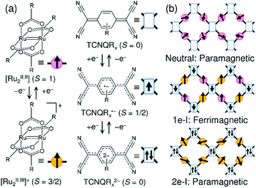 | ||
| Fig. 1 (a) Representations of [RuII,II2(RCO2)4] (S = 1) as a donor (D) with its oxidized forms of [RuII,III2(RCO2)4]+ (S = 3/2) and TCNQRx (S = 0) as an acceptor (A) with its reduced forms of TCNQRx˙− (S = 1/2) and TCNQRx2− (S = 0). (b) Schematic figures of the electronic state and magnetic property expected in a [Ru2]2TCNQRx framework. | ||
Herein, we present a new antiferromagnet with TN = 97 K, [{Ru2(m-ClPhCO2)4}2(TCNQ(MeO)2)]·3.3DCM·2TCE (1; m-ClPhCO2− = meta-chlorobenzoate, DCM = dichloromethane, TCE = 1,1,2,2-tetrachloroethane), which undergoes a metamagnetic transition on the application of fields less than 0.5 T, eventually resulting in a field-induced ferrimagnet. A comparison of the magnetostructural correlations among this type of layered magnets reveals that this class of antiferromagnets with interlayer antiferromagnetic interactions tends to have a shorter interlayer translational distance (l2), i.e., interlayer inter-unit distance such as [Ru2]⋯[Ru2] or TCNQRx⋯TCNQRx, than in the class of ferrimagnets with interlayer ferromagnetic interactions.
Results and discussion
Syntheses and characterization
Compound 1 was synthesized via a unit-assembly method using two types of subunits of coordinating donors (TCNQ(MeO)2) in TCE and coordinating acceptor ([RuII,II2(m-ClPhCO2)4(THF)2]) in DCM, which has been previously used for similar [Ru2]2TCNQRx materials.31–58 This reaction involves a redox reaction between the electron-donor [RuII,II2] complex and the acceptor TCNQ(MeO)2, so the reaction should be carried out very slowly using a solvent-diffusion method in a narrow glass tube to obtain a crystalline sample (see Experimental section). The obtained compound contains crystallization solvents, which were relatively stable at room temperature; however, they begin to be eliminated when the temperature is raised up to 373 K, as indicated by thermal gravimetric analysis curve (Fig. S1, ESI†).The infrared spectra of 1 exhibited two characteristic ν(C![[triple bond, length as m-dash]](https://www.rsc.org/images/entities/char_e002.gif) N) stretches at 2195 and 2161 cm−1, which are lower frequencies than the corresponding band at 2220 cm−1 of neutral TCNQ(MeO)2 (Fig. S2, ESI†), indicating the presence of the reduced form of the TCNQ(MeO)2 moiety. UV powder reflection spectra of 1 measured on its pellet diluted with BaSO4 show a wide range of absorptions in the low-energy region of E < 1.5 eV, which are attributed to overlapped bands characteristically found in this type of charge transfer compounds with a π–π* transition on the TCNQ(MeO)˙− moieties59 and charge transfer bands between [Ru2] units and TCNQ(MeO)˙−, including the ligand-to-metal charge transfer (LMCT) of TCNQ(MeO)2˙− → [RuII,III2]+ and metal-to-ligand charge transfer (MLCT) of [RuII,II2] → TCNQ(MeO)2˙− (Fig. S3, ESI†).34,41,46
N) stretches at 2195 and 2161 cm−1, which are lower frequencies than the corresponding band at 2220 cm−1 of neutral TCNQ(MeO)2 (Fig. S2, ESI†), indicating the presence of the reduced form of the TCNQ(MeO)2 moiety. UV powder reflection spectra of 1 measured on its pellet diluted with BaSO4 show a wide range of absorptions in the low-energy region of E < 1.5 eV, which are attributed to overlapped bands characteristically found in this type of charge transfer compounds with a π–π* transition on the TCNQ(MeO)˙− moieties59 and charge transfer bands between [Ru2] units and TCNQ(MeO)˙−, including the ligand-to-metal charge transfer (LMCT) of TCNQ(MeO)2˙− → [RuII,III2]+ and metal-to-ligand charge transfer (MLCT) of [RuII,II2] → TCNQ(MeO)2˙− (Fig. S3, ESI†).34,41,46
Theoretical prediction of the ionicity of 1
If possible, the use of an ionicity diagram is convenient for predicting the ionicity of charge transfer compounds. Recently, we proposed a simple ionicity diagram to predict the electronic state, either neutral (N) or ionic (I), of this series of D/A-MOFs.1 The ionicity is indicated by the energy gap between the highest occupied molecular orbital (HOMO) level of D and the lowest occupied molecular orbital (LUMO) level of A, ELUMO(A) − EHOMO(D) = ΔEH–L(DA), with boundaries of ΔEH–L(DA) > 0 and ΔEH–L(DA) < 0 for the N and I regimes, respectively (the diagram is square with a vertical axis of ΔEH–L(DA) and a horizontal axis of the differences in the respective first redox potentials, ΔE1/2(DA) = 1E1/2(A) − 1E1/2(D); Fig. S4, ESI†).1,44 The EHOMO(D) value calculated based on [Ru2(m-ClPhCO2)4(THF)2] and the ELUMO(A) value for TCNQ(MeO)2 are −4.5323 and −4.6262 eV, respectively;1,29,35,44,45 thus, ΔEH–L(DA) is −0.0939 eV, which suggests the formation of an ionic state in the assembly formed by the reaction of these components. To determine the degree of ionicity, i.e., the 1e-I state or the 2e-I state, another diagram plotting ΔEH–L(DA) vs. the on-site Coulomb repulsion (U = |2E1/2(A) − 1E1/2(A)|, where 2E1/2(A) and 1E1/2(A) are the second and first redox potentials of TCNQRx, respectively) was used, in which a boundary energy of ΔEH–L(DA)/eV = −0.006405U + 2.9110 (an empirically estimated line) separates the 1e-I state and the 2e-I state.1,35,44 TCNQ(MeO)2 has U = 481 mV,44 so the boundary energy level between the 1e-I and 2e-I states for TCNQ(MeO)2 was predicted to be −0.1917 eV, i.e., the ΔEH–L(DA) region from −0.1917 eV to 0 eV corresponds to the 1e-I regime for the assemblies with TCNQ(MeO)2 (Fig. S5, ESI†), which is consistent with the 1e-I state in 1.Structure of 1 and the evaluation of the charge distribution
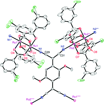
Compound 1 crystallized in the triclinic space group P![[1 with combining macron]](https://www.rsc.org/images/entities/char_0031_0304.gif) , in which two types of [Ru2] units and one TCNQ(MeO)2 unit with an inversion center in each unit were determined as the asymmetric unit (Z = 1). An ORTEP drawing of the formula unit with an atom-numbering scheme is shown in Fig. 2. The [Ru2] and TCNQ(MeO)2 units, acting as a linear coordination acceptor and an μ4-bridging coordination donor, respectively, form a fishnet-like hexagonal two-dimensional network similar to those of other D2A systems reported previously (Fig. 3a).31,32,34–37,39,41,44–46,51,52 Relevant geometrical parameters are listed in Table S1 (ESI†). The Ru–Ru bond distances are 2.2814(7) and 2.2830(7) Å for Ru(1)–Ru(1) and Ru(2)–Ru(2), respectively, slightly longer than that of [RuII,II2(m-ClPhCO2)4(THF)2] (2.2682(3) Å).29 The Ru–Oeq (Oeq = carboxylate oxygen) bond distances are more sensitive to the oxidation state and are generally found in the range of 2.07–2.09 Å for [RuII,II2] and 2.01–2.03 Å for [RuII,III2]+.2,3 The average Ru–Oeq bond lengths for the [Ru(1)2] and [Ru(2)2] units are 2.018 and 2.058 Å, which indicate that the [Ru(1)2] and [Ru(2)2] units are likely to be [RuII,III2]+ and [RuII,II2], respectively (i.e., a charge-distributed form of D+D0A−; vide infra). The Ru–Nax (Nax = cyano nitrogen of TCNQ(MeO)2) distances are 2.219 and 2.253 Å for Ru(1)–N(1) and Ru(2)–N(2), respectively, which also reflects the respective oxidation states of each [Ru2] unit; those for [RuII,II2] tend to be longer than those for [RuII,III2]+.31,38,47,49,51,54,55
, in which two types of [Ru2] units and one TCNQ(MeO)2 unit with an inversion center in each unit were determined as the asymmetric unit (Z = 1). An ORTEP drawing of the formula unit with an atom-numbering scheme is shown in Fig. 2. The [Ru2] and TCNQ(MeO)2 units, acting as a linear coordination acceptor and an μ4-bridging coordination donor, respectively, form a fishnet-like hexagonal two-dimensional network similar to those of other D2A systems reported previously (Fig. 3a).31,32,34–37,39,41,44–46,51,52 Relevant geometrical parameters are listed in Table S1 (ESI†). The Ru–Ru bond distances are 2.2814(7) and 2.2830(7) Å for Ru(1)–Ru(1) and Ru(2)–Ru(2), respectively, slightly longer than that of [RuII,II2(m-ClPhCO2)4(THF)2] (2.2682(3) Å).29 The Ru–Oeq (Oeq = carboxylate oxygen) bond distances are more sensitive to the oxidation state and are generally found in the range of 2.07–2.09 Å for [RuII,II2] and 2.01–2.03 Å for [RuII,III2]+.2,3 The average Ru–Oeq bond lengths for the [Ru(1)2] and [Ru(2)2] units are 2.018 and 2.058 Å, which indicate that the [Ru(1)2] and [Ru(2)2] units are likely to be [RuII,III2]+ and [RuII,II2], respectively (i.e., a charge-distributed form of D+D0A−; vide infra). The Ru–Nax (Nax = cyano nitrogen of TCNQ(MeO)2) distances are 2.219 and 2.253 Å for Ru(1)–N(1) and Ru(2)–N(2), respectively, which also reflects the respective oxidation states of each [Ru2] unit; those for [RuII,II2] tend to be longer than those for [RuII,III2]+.31,38,47,49,51,54,55
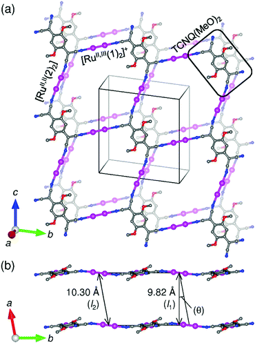 | ||
| Fig. 3 Packing diagrams projected onto the (1 0 0) plane (a) and along the c-axis (b), where C, N, and Ru atoms are represented in gray, blue, and purple, respectively. The equatorial carboxylate ligands for [Ru2] units, crystallization solvents, and hydrogen atoms are omitted for clarity. The interlayer vertical distance l1 and the interlayer translational distance l2 in Fig. 2b are defined by the vertical distance and the nearest [Ru2]⋯[Ru2] distance between the (100) planes, respectively, where θ is defined as a tilt angle made by l1 and l2. | ||
Correspondingly, the TCNQ(MeO)2 moiety has a mono-anionic form (TCNQ(MeO)2˙−). The Kistenmacher relationship for TCNQRxρ,60ρ = A[c/(b + d)] + B with A = −41.667 and B = 19.833, was evaluated based on neutral TCNQ (ρ = 0)61 and RbTCNQ (ρ = −1),62 where b, c, and d are the respective C–C bond distances between the 7,9-, 1,7-, and 1,2-positions in the TCNQ moiety (Table S2, ESI†). The estimated ρ value for the TCNQ(MeO)2 moiety is −1.08, i.e., ρ ≈ −1, which is in good agreement with the IR data and with the valance charges of the [Ru2] units, indicating a one-electron transfer from a [Ru(1)2] unit to TCNQ(MeO)2, resulting in a formal oxidation state of [{RuII,III(1)2}+–(TCNQ(MeO)2˙−)–{RuII,II(2)2}]).
The two-dimensional network lies on the (100) plane, resulting in a layer structure with an interlayer vertical distance of 9.82 Å (l1 in Fig. 3b). The interlayer translational distance is defined as the nearest interlayer [Ru2]⋯[Ru2] or TCNQ(MeO)2⋯TCNQ(MeO)2 distance, corresponding to the cell dimension a in 1, and is 10.30 Å (l2 in Fig. 3b). The layers are stacked in an almost in-phase manner, but translated with a tilt angle of θ = 17.5°, related by l1 = l2![[thin space (1/6-em)]](https://www.rsc.org/images/entities/char_2009.gif) cos
cos![[thin space (1/6-em)]](https://www.rsc.org/images/entities/char_2009.gif) θ.44 Several DCM and TCE molecules are intercalated as interstitial crystallization solvents in the void space between the layers (Fig. S6, ESI†).
θ.44 Several DCM and TCE molecules are intercalated as interstitial crystallization solvents in the void space between the layers (Fig. S6, ESI†).
Magnetic properties
The temperature dependence of the magnetic susceptibility (χ = M/H) was measured for a polycrystalline sample of 1 applying a 1 kOe dc field in the temperature range of 1.82 to 300 K (cooling process). The χ and χT products are plotted in Fig. 4a. The χT value of 2.61 cm3 K mol−1 at 300 K is much higher than that expected from the spin-only value of 2.00 cm3 K mol−1 for the N state with a set of two S = 1 spins for the isolated [RuII,II2] units (g = 2.00) but smaller than 3.25 cm3 K mol−1, which is expected for a paramagnetic 1e-I state with isolated spins of S = 3/2 for [RuII,III2]+, S = 1 for [RuII,II2], and S = 1/2 for TCNQRx˙−, indicating that 1 is in a ferrimagnetically arranged 1e-I state even at 300 K. Upon decreasing the temperature, the χT value gradually increased, reaching 31.4 cm3 K mol−1 at 110 K and abruptly increasing to 631 cm3 K mol−1 at 82 K. This was followed by a sudden decrease to 17.1 cm3 K mol−1 at 1.8 K. The χ–T plot also displays an abrupt increase of χ at around 100 K, but no decrease is observed at lower temperatures at H = 1 kOe. The abrupt increase of both χ and χT at around 100 K indicates the onset of long-range ferrimagnetic ordering.32,38,39,41,45,46 However, the χ–T plots measured by applying an external field of less than 200 Oe contain a peak at around 97 K, indicating a spin flip from an antiferromagnetic (AF) phase to a paramagnetic (P) phase (Fig. 4b). To thoroughly investigate the nature of the ordering, the temperature dependence of the ac magnetic susceptibility (χ′, real part; χ′′, imaginary part) was measured under zero dc field with a 3 Oe oscillating field in the frequency range of 1 Hz to 1.5 kHz (Fig. 5). The χ′ value exhibits a single distinct peak at 97 K without any noticeable frequency dependence, and there are no anomalies in the χ′′ value, indicating the occurrence of an antiferromagnetic phase transition with TN = 97 K.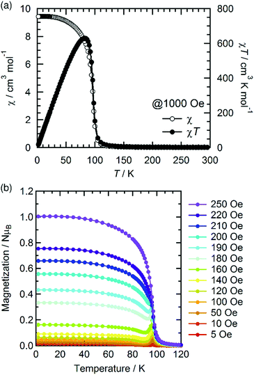 | ||
| Fig. 4 Temperature dependence of χ and χT measured under a 1 kOe dc field (a) and the field-cooled magnetization curves measured under different external fields from 5 to 250 Oe (b) for 1. | ||
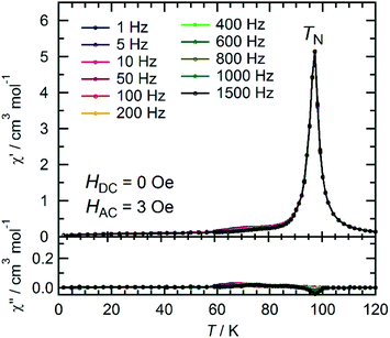 | ||
| Fig. 5 Temperature dependence of the ac magnetic susceptibilities χ′ (in-phase) and χ′′ (out-of-phase) at zero dc field and a 3 Oe ac oscillating field for 1. | ||
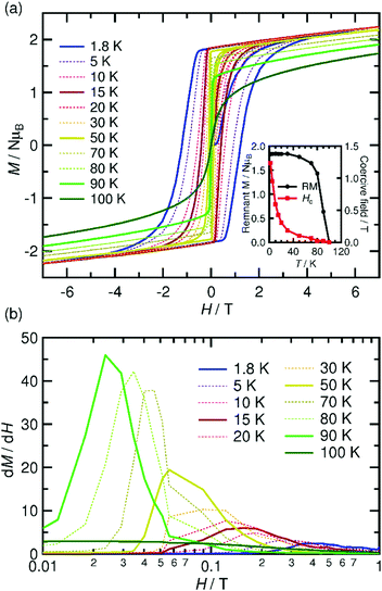
The spin–flip phenomenon can also be observed in the field dependence of the magnetization measured in the field range of −7 to 7 T at various temperatures (1.8–100 K, Fig. 6a); the magnetization variation in the initial field sweep from zero to 7 T undergoes a spin flip at a flipping field (Hex), which is detectable in the dM/dH plot (Fig. 6b). Ultimately, these data produce an H–T phase diagram for 1, as shown in Fig. 7, showing a typical diagram for metamagnetism. Nevertheless, after achieving the P-phase upon the application of a field, 1 maintains a ferrimagnetically ordered phase, even at low temperatures below TN, showing field-induced ferrimagnetism with a remnant magnetization (RM) of 1.83 μB and a large coercivity (Hc) of 1.2 T at 1.8 K (Fig. 6a). The Hc quasi-exponentially decreases with increasing temperature and finally disappears at ca. 90 K, very close to TN (inset of Fig. 6a). The RM begins to decrease rapidly at T > 70 K and disappears at 100 K (inset of Fig. 6a), indicating the relatively hard character of the magnetic domain for 1. The magnetization at 7 T (Ms) is 2.24 μB at 1.8 K, which is significantly smaller than 4 μB for a ferrimagnetically coupled total spin (g = 2.00). The small Ms value could be due to the strong intrinsic anisotropy of the component [Ru2] units (D ≈ 270 cm−1 for [RuII,II2] with S = 1, and D ≈ 70 cm−1 for [RuII,III2] with S = 3/2)2–5 along with the structural anisotropy expected for layered magnets. The nature of the strong anisotropy in 1 could allow the observation of field-induced ferrimagnetism with a large RM and Hc.
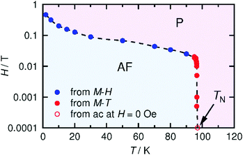 | ||
| Fig. 7 H–T phase diagram for 1, where AF and P represent the antiferromagnetic and paramagnetic phases, respectively. TN (97 K) was determined from the χ′ versus T data at H = 0 (Fig. 4). | ||
Magnetostructural correlation concerning interlayer dipole interactions
Some [Ru2]2TCNQRx-type magnets with a layered framework have been reported so far, but the spin-flipping field at 1.8 K, Hex = 0.46 T, in 1 is relatively small compared to those in other antiferromagnets (e.g., Hex = 4.74 T for [{Ru2(CF3CO2)4}2(TCNQF4)]·3(p-xylene) (2, CF3CO2− = trifluoroacetate; TCNQF4 = 2,3,5,6-tetrafluoro-7,7,8,8-tetracyanoquinodimethane),32,34Hex = 1.0 T for [{Ru2(o-FPhCO2)4}2(BTDA-TCNQ)]·4DCM (3, BTDA-TCNQ = bis[1,2,5]thiadizolotetracyanoquinodimethane),39Hex = 1.3 T for [{Ru2(o-ClPhCO2)4}{TCNQ(MeO)2}]·DCM (4, o-ClPhCO2− = ortho-chlorobenzoate),41 and Hex = 1.5 T for [{Ru2(o-FPhCO2)4}{TCNQ(MeO)2}]·4DCM (5, o-FPhCO2− = ortho-fluorobenzoate);45Fig. 8a). Probably, the interlayer environment, including structural factors, is the main cause of this phenomenon; indeed, this question has been a longstanding theme in the subject of low-dimensional structural magnets.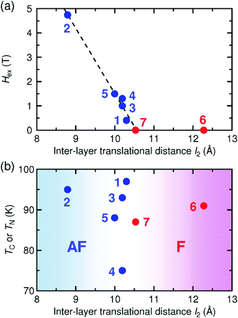 | ||
| Fig. 8 Spin-flipping field (Hex) at 1.8 K (a) and magnetic phase transition temperature (TC or TN) (b) as a function of interlayer translational distance l2 for 1 and relevant [Ru2]2TCNQRx layered magnets reported previously, where the compounds with ferromagnetic and antiferromagnetic ground states are colored in red and blue, respectively: 1, [{Ru2(m-ClPhCO2)4}2{TCNQ(MeO)2}]·3.3DCM·2TCE; 2, [{Ru2(CF3CO2)4}2(TCNQF4)]·3(p-xylene);32,343, [{Ru2(o-FPhCO2)4}2(BTDA-TCNQ)]·4DCM;394, [{Ru2(o-ClPhCO2)4}{TCNQ(MeO)2}]·DCM;415, [{Ru2(o-FPhCO2)4}{TCNQ(MeO)2}]·4DCM;456, [{Ru2(2,4,6-F3PhCO2)4}(TCNQ)]·2DCM·2(p-xylene);46 and 7, [{Ru2(p-FPhCO2)4}(BTDA-TCNQ)]·2DCM·2(p-chlorotoluene).39 | ||
To investigate the cause of the small spin-flipping field, the Hex values of these antiferromagnets were plotted as a function of the vertical distance (l1) (Fig. S7, ESI†) and the translational distance (l2) (Fig. 8a). The Hex value decreases with increasing l2; thus, the smaller Hex value in 1 can be ascribed to a larger l2 value. Intriguingly, Hex is expected to be zero at l2 ≈ 10.5 Å, suggesting the existence of a threshold distance separating the interlayer antiferromagnetic and ferromagnetic interactions. Indeed, the series of ferrimagnets is found in the region where l2 ≥ 10.5 Å, at which point Hex is zero (Fig. 8a).39,46 In contrast, the correlation with l1 is unclear (Fig. S7, ESI†), indicating that l2 is a more appropriate parameter to make a correlation with the interlayer magnetic interaction in the [Ru2]2TCNQRx layered system.
The TC or TN values have no linear correlation with l2, but reveal a rough boundary between ferrimagnetic (l2 ≥ 10.3 Å) and antiferromagnetic (l2 ≤ 10.3 Å) states; that is, a shorter l2 tends to result in antiferromagnets (Fig. 8b). This observation suggests that the transition temperature is, instead, strongly associated with the intra-layer magnetostructural correlation, such as the overlap between the frontier π* SOMOs (singly occupied molecular orbital) of [RuII,II2]/[RuII,III2]+ and TCNQ(MeO)2˙−, which determines the magnitude of exchange coupling, as well as subsequent interlayer dipole interactions. Unfortunately, we do not have any appropriate answer for why l2 is more critical than l1 in the determination of magnetic ordering, but our investigation indicates that interlayer local spin–spin interactions still play a key role in the interlayer coupling between ordered moments. To clarify this question, more example compounds should be investigated.
Conclusions
The reaction of [RuII,II2(m-ClPhCO2)4(THF)2] and TCNQ(MeO)2 led to a two-dimensional layered assembly with a D2A formula (1). The electronic state of 1 was assigned to be the charge-distributed 1e-I state with [{Ru2}+–TCNQ˙−–{Ru2}]. Strong antiferromagnetic couplings through the dπ*–pπ* orbital overlaps between [RuII,II2] (S = 1) or [RuII,III2] (S = 3/2) and TCNQ˙− (S = 1/2) result in intra-layer ferrimagnetic ordering, but subsequent interlayer antiferromagnetic coupling eventually results in the formation of an antiferromagnet with TN = 97 K. Interestingly, 1 becomes a non-volatile ferrimagnet (i.e., field-induced ferrimagnet) on applying an external field greater than Hex.In layered magnetic systems such as 1, the nature of the interlayer interactions, i.e., either antiferromagnetic or ferromagnetic, determines the nature of the magnet, which is strongly affected by the interlayer environment and layer-stacking. Hence, it is difficult to pre-organize the interlayer interactions via self-assembly for layered systems, and an alternative method must be used, such as the insertion of another paramagnetic species.49 Thus, the control of inter-framework interactions remains a crucial issue in the design of low-dimensional magnetic systems. That is to say, the inter-framework interactions are a trigger to induce drastic changes in the magnetic phase of low-dimensional magnets; this is an intriguing advantage in such low-dimensional magnetic systems.
A comparison of the [Ru2]2TCNQRx systems revealed the existence of threshold value of ca. 10.5 Å in the interlayer translational distance l2. Thus, the interlayer translational distance (i.e., inter-unit distances) l2 is, empirically, more important than the interlayer vertical distance l1. The value of l2 is not easy to control because it involves the packing mode of the layers, as well as the interlayer steric hindrance; however, the threshold value offers a promising strategy for designing this type of D/A-MOFs with intriguing magnetic properties, such as chemical/physical stimuli-induced magnetic switching.
Experimental section
General procedures and materials
All synthetic procedures were performed under an inert atmosphere using standard Schlenk techniques and a commercial glovebox. All chemicals were purchased from commercial sources and were of reagent grade. The solvents were dried using common drying agents and distilled under ultrapure nitrogen before use. The starting materials for the [RuII,II2] units were prepared by following previously reported methods.29 Fresh samples picked out of the mother liquids and used for magnetic measurements.Synthesis of 1
A TCE solution (30 mL) of TCNQ(MeO)2 (20 mg, 0.075 mmol) was divided into 2 mL aliquots, and each aliquot was placed in a narrow-diameter sealed glass tube (ϕ 8 mm) as the bottom layer. The middle layer, a mixture of DCM and TCE (1![[thin space (1/6-em)]](https://www.rsc.org/images/entities/char_2009.gif) :
:![[thin space (1/6-em)]](https://www.rsc.org/images/entities/char_2009.gif) 1 v/v; 1 mL), was added carefully to the bottom layer. A 2 mL aliquot of a DCM solution (30 mL) of [Ru2(m-ClPhCO2)4(THF)2] (145 mg, 0.13 mmol) was carefully added on top of the middle layer in each tube. The glass tubes were left undisturbed in the glovebox for two weeks or more, after which block-shaped dark brown crystals of 1 were obtained. Yield: 12.9%. X-ray crystallography measurements indicated that the crystals contained crystallization solvents (i.e., 2DCM·2TCE), although the elemental analysis indicated crystallization solvent contents of 3.3DCM·2TCE. Elemental analysis (%) calcd for C77.3H50.6Cl22.6N4O18Ru4: C, 36.71; H, 2.02; N, 2.22; found: C, 36.68; H, 2.06; N, 2.39. FT-IR (KBr, cm−1): ν(C
1 v/v; 1 mL), was added carefully to the bottom layer. A 2 mL aliquot of a DCM solution (30 mL) of [Ru2(m-ClPhCO2)4(THF)2] (145 mg, 0.13 mmol) was carefully added on top of the middle layer in each tube. The glass tubes were left undisturbed in the glovebox for two weeks or more, after which block-shaped dark brown crystals of 1 were obtained. Yield: 12.9%. X-ray crystallography measurements indicated that the crystals contained crystallization solvents (i.e., 2DCM·2TCE), although the elemental analysis indicated crystallization solvent contents of 3.3DCM·2TCE. Elemental analysis (%) calcd for C77.3H50.6Cl22.6N4O18Ru4: C, 36.71; H, 2.02; N, 2.22; found: C, 36.68; H, 2.06; N, 2.39. FT-IR (KBr, cm−1): ν(C![[triple bond, length as m-dash]](https://www.rsc.org/images/entities/char_e002.gif) N) 2195, 2161.
N) 2195, 2161.
General physical measurements
A thermogravimetric analyses (TGA) were recorded on a Shimadzu DTG-60H apparatus under N2 atmosphere in the temperature range between 298 and 673 K at a heating rate of 5 K min−1. The infrared spectra were measured on KBr disks with a Jasco FT-IR 620 spectrophotometer. Powder reflection spectra were measured on pellets diluted with BaSO4 using a Shimadzu UV-3150 spectrometer. The magnetic susceptibility measurements were conducted with a Quantum Design SQUID magnetometer (MPMS-XL) in temperature and dc field ranges of 1.8 to 300 K and −7 to 7 T, respectively. Polycrystalline samples embedded in liquid paraffin were measured. The experimental data were corrected for the sample holder and liquid paraffin and for the diamagnetic contributions calculated from the Pascal constants.63Crystallography
Single crystals with dimensions of 0.140 × 0.113 × 0.055 mm3 were mounted on cryo-loops using Nujol and cooled by a stream of N2 gas. Measurements were made on a CCD diffractometer (Rigaku Saturn 70) with graphite monochromated Mo-Kα radiation (λ = 0.71075 Å). The structures were solved by direct methods (SIR 92)64 and expanded using Fourier techniques (DIRDIF99).65 All non-hydrogen atoms were refined anisotropically. Hydrogen atoms were introduced as fixed contributors. Full-matrix least-squares refinements of F2 were based on observed reflections and variable parameters and converged with unweighted and weighted agreement factors of R1 = Σ||Fo| − |Fc||/Σ|Fo| (I > 2.00σ(I)) and wR2 = [Σw(Fo2 − Fc2)2/Σw(Fo2)2]1/2 (all data). All calculations were performed using the CrystalStructure crystallographic software package.66 The structural diagrams were prepared using VESTA.67 CCDC 1586453.†Crystallographic data for 1
Formula: C76H48Cl20N4O18Ru4, Mr = 2418.57, triclinic, P![[1 with combining macron]](https://www.rsc.org/images/entities/char_0031_0304.gif) (#2), a = 10.295(3) Å, b = 15.211(4) Å, c = 15.710(4) Å, α = 97.505(3)°, β = 103.952(3)°, γ = 98.491(2)°, V = 2325.8(10) Å3, T = 93(1) K, Z = 1, Dcalc = 1.727 g cm−3, F000 = 1192.00, λ = 0.71075 Å, μ(Mo-Kα) = 12.757 cm−1, 15
(#2), a = 10.295(3) Å, b = 15.211(4) Å, c = 15.710(4) Å, α = 97.505(3)°, β = 103.952(3)°, γ = 98.491(2)°, V = 2325.8(10) Å3, T = 93(1) K, Z = 1, Dcalc = 1.727 g cm−3, F000 = 1192.00, λ = 0.71075 Å, μ(Mo-Kα) = 12.757 cm−1, 15![[thin space (1/6-em)]](https://www.rsc.org/images/entities/char_2009.gif) 622 measured reflections, 7980 unique (Rint = 0.0198). R1 = 0.0503 (I > 2σ(I)), R1 = 0.0612 (all data), and wR2 = 0.1569 with goodness-of-fit (GOF) = 1.076.
622 measured reflections, 7980 unique (Rint = 0.0198). R1 = 0.0503 (I > 2σ(I)), R1 = 0.0612 (all data), and wR2 = 0.1569 with goodness-of-fit (GOF) = 1.076.
Conflicts of interest
There are no conflicts to declare.Acknowledgements
This study was supported by a Grant-in-Aid for Scientific Research (Grant No. 16H02269) from the Ministry of Education, Culture, Sports, Science, and Technology, Japan; a Grand-in-Aid for Scientific Research on Innovative Areas (“π-System Figuration” Area 2601, No. JP17H05137) from the Japan Society for the Promotion of Science (JSPS); and the E-IMR project.Notes and references
- H. Miyasaka, Acc. Chem. Res., 2013, 46, 248–257 CrossRef CAS PubMed
.
-
F. A. Cotton and R. A. Walton, Multiple Bonds between Metal Atoms, Oxford University Press, Oxford, 2nd edn, 1993 Search PubMed
.
- M. A. S. Aquino, Coord. Chem. Rev., 1998, 170, 141–202 CrossRef CAS
.
- M. A. S. Aquino, Coord. Chem. Rev., 2004, 248, 1025–1045 CrossRef CAS
.
- M. Mikuriya, D. Yoshioka and M. Handa, Coord. Chem. Rev., 2006, 250, 2194–2211 CrossRef CAS
.
- X.-Y. Wang, C. Avendaño and K. R. Dunbar, Chem. Soc. Rev., 2011, 40, 3213–3238 RSC
49, 3266–3296.
- J. S. Miller, Chem. Soc. Rev., 2011, 49, 3266–3296 RSC
.
- J. S. Miller, Dalton Trans., 2006, 2742–2749 RSC
.
- Y. Liao, W. W. Shum and J. S. Miller, J. Am. Chem. Soc., 2002, 124, 9336–9337 CrossRef CAS PubMed
.
- T. E. Vos, Y. Liao, W. W. Shum, J.-H. Her, P. W. Stephens, W. M. Reiff and J. S. Miller, J. Am. Chem. Soc., 2004, 126, 11630–11639 CrossRef CAS PubMed
.
- T. E. Vos and J. S. Miller, Angew. Chem., Int. Ed., 2005, 33, 2416–2419 CrossRef PubMed
.
- J. S. Miller, T. E. Vos and W. W. Shum, Adv. Mater., 2005, 17, 2251–2254 CrossRef CAS
.
- J. S. Miller, CrystEngComm, 2005, 7, 458–461 RSC
.
- W. Liu, E. N. Nfor, Y.-Z. Li, J.-L. Zuo and X.-Z. You, Inorg. Chem. Commun., 2006, 9, 923–925 CrossRef CAS
.
- W. W. Shum, J.-H. Her, P. W. Stephens, Y. Lee and J. S. Miller, Adv. Mater., 2007, 19, 2910–2913 CrossRef CAS
.
- W. W. Shum, J. N. Schaller and J. S. Miller, J. Phys. Chem. C, 2008, 112, 7936–7938 CAS
.
- B. S. Kennon, J.-H. Her, P. W. Stephens and J. S. Miller, Inorg. Chem., 2009, 48, 6117–6123 CrossRef CAS PubMed
.
- R. S. Fishman, S. Okamoto and J. S. Miller, Phys. Rev. B: Condens. Matter Mater. Phys., 2009, 80, 140416 CrossRef
.
- B. S. Kennon, K. H. Stone, P. W. Stephens and J. S. Miller, CrystEngComm, 2009, 11, 2185–2191 RSC
.
- B. S. Kennon and J. S. Miller, Inorg. Chem., 2010, 49, 5542–5545 CrossRef CAS PubMed
.
- B. S. Kennon, K. H. Stone, P. W. Stephens and J. S. Miller, Inorg. Chim. Acta, 2010, 363, 2137–2143 CrossRef CAS
.
- R. S. Fishman, W. W. Shum and J. S. Miller, Phys. Rev. B: Condens. Matter Mater. Phys., 2010, 81, 172407 CrossRef
.
- J. G. DaSilva and J. S. Miller, Inorg. Chem., 2013, 52, 1418–1423 CrossRef CAS PubMed
.
- F. Haque, E. del Barco, R. S. Fishman and J. S. Miller, Polyhedron, 2013, 64, 73–76 CrossRef CAS
.
- K. R. O’Neal, Z. Liu, J. S. Miller, R. S. Fishman and J. L. Musfeldt, Phys. Rev. B: Condens. Matter Mater. Phys., 2014, 90, 104301 CrossRef
.
- K. H. Stone, P. W. Stephens, M. B. Wainer, R. A. Davidson and J. S. Miller, Inorg. Chim. Acta, 2015, 424, 116–119 CrossRef CAS
.
- H. Miyasaka, Y. Asai, N. Motokawa, K. Kubo and M. Yamashita, Inorg. Chem., 2010, 49, 9116–9118 CrossRef CAS PubMed
.
- H. Miyasaka, N. Motokawa, R. Atsuumi, H. Kamo, Y. Asai and M. Yamashita, Dalton Trans., 2011, 40, 673–682 RSC
.
- W. Kosaka, M. Itoh and H. Miyasaka, Dalton Trans., 2015, 44, 8156–8168 RSC
.
- Y. Sekine, W. Kosaka, H. Kano, C. Dou, T. Yokoyaka and H. Miyasaka, Dalton Trans., 2016, 45, 7427–7434 RSC
.
- H. Miyasaka, C. S. Campos-Fernández, R. Clérac and K. R. Dunbar, Angew. Chem., Int. Ed., 2000, 39, 3831–3835 CrossRef CAS
.
- H. Miyasaka, T. Izawa, N. Takahashi, M. Yamashita and K. R. Dunbar, J. Am. Chem. Soc., 2006, 128, 11358–11359 CrossRef CAS PubMed
.
- N. Motokawa, T. Oyama, S. Matsunaga, H. Miyasaka, K. Sugimoto, M. Yamashita, N. Lopez and K. R. Dunbar, Dalton Trans., 2008, 4099–4102 RSC
.
- H. Miyasaka, N. Motokawa, S. Matsunaga, M. Yamashita, K. Sugimoto, T. Mori, N. Toyota and K. R. Dunbar, J. Am. Chem. Soc., 2010, 132, 1532–1544 CrossRef CAS PubMed
.
- K. Nakabayashi, M. Nishio, K. Kubo, W. Kosaka and H. Miyasaka, Dalton Trans., 2012, 41, 6072–6074 RSC
.
- M. Nishio, N. Motokawa, M. Takemura and H. Miyasaka, Dalton Trans., 2013, 42, 15898–15901 RSC
.
- M. Nishio, N. Motokawa and H. Miyasaka, CrystEngComm, 2015, 17, 7618–7622 RSC
.
- N. Motokawa, H. Miyasaka, M. Yamashita and K. R. Dunbar, Angew. Chem., Int. Ed., 2008, 47, 7760–7763 CrossRef CAS PubMed
.
- N. Motokawa, T. Oyama, S. Matsunaga, H. Miyasaka, M. Yamashita and K. R. Dunbar, CrystEngComm, 2009, 11, 2121–2130 RSC
.
- N. Motokawa, H. Miyasaka and M. Yamashita, Dalton Trans., 2010, 39, 4724–4726 RSC
.
- N. Motokawa, S. Matsunaga, S. Takaishi, H. Miyasaka, M. Yamashita and K. R. Dunbar, J. Am. Chem. Soc., 2010, 132, 11943–11951 CrossRef CAS PubMed
.
- H. Miyasaka, T. Morita and M. Yamashita, Chem. Commun., 2011, 47, 271–273 RSC
.
- H. Fukunaga, W. Kosaka and H. Miyasaka, Chem. Lett., 2014, 43, 541–543 CrossRef CAS
.
- W. Kosaka, T. Morita, T. Yokoyama, J. Zhang and H. Miyasaka, Inorg. Chem., 2015, 54, 1518–1527 CrossRef CAS PubMed
.
- H. Fukunaga, T. Yoshino, H. Sagayama, J. Yamaura, T. Arima, W. Kosaka and H. Miyasaka, Chem. Commun., 2015, 51, 7795–7798 RSC
.
- W. Kosaka, H. Fukunaga and H. Miyasaka, Inorg. Chem., 2015, 54, 10001–10006 CrossRef CAS PubMed
.
- M. Nishio, N. Hoshino, W. Kosaka, T. Akutagawa and H. Miyasaka, J. Am. Chem. Soc., 2013, 135, 17715–17718 CrossRef CAS PubMed
.
- M. Nishio and H. Miyasaka, Inorg. Chem., 2014, 53, 4716–4723 CrossRef CAS PubMed
.
- H. Fukunaga and H. Miyasaka, Angew. Chem., Int. Ed., 2015, 54, 569–573 CAS
.
- Y. Sekine, M. Tonouchi, T. Yokoyama, W. Kosaka and H. Miyasaka, CrystEngComm, 2017, 19, 2300–2304 RSC
.
- K. Taniguchi, K. Narushima, J. Mahin, W. Kosaka and H. Miyasaka, Angew. Chem., Int. Ed., 2016, 55, 5238–5242 CrossRef CAS PubMed
.
- K. Taniguchi, K. Narushima, H. Sagayama, W. Kosaka, N. Shito and H. Miyasaka, Adv. Funct. Mater., 2017, 27, 1604990 CrossRef
.
- K. Taniguchi, K. Narushima, K. Yamagishi, N. Shito, W. Kosaka and H. Miyasaka, Jpn. J. Appl. Phys., 2017, 56, 060307 CrossRef
.
- W. Kosaka, Y. Takahashi, M. Nishio, K. Narushima, H. Fukunaga and H. Miyasaka, Adv. Sci., 2017 DOI:10.1002/advs.201700526
.
- H. Miyasaka, N. Motokawa, T. Chiyo, M. Takemura, M. Yamashita, H. Sagayama and T. Arima, J. Am. Chem. Soc., 2011, 133, 5338–5345 CrossRef CAS PubMed
.
- K. Nakabayashi and H. Miyasaka, Chem. – Eur. J., 2014, 20, 5121–5131 CrossRef PubMed
.
- K. Nakabayashi, M. Nishio and H. Miyasaka, Inorg. Chem., 2016, 55, 2473–2480 CrossRef CAS PubMed
.
- Y. Sekine, T. Yokoyama, N. Hoshino, M. Ishizaki, K. Kanaizuka, T. Akutagawa, M. Haga and H. Miyasaka, Chem. Commun., 2016, 52, 13983–13986 RSC
.
- K. Kamarás, G. Grüner and G. A. Sawatzky, Solid State Commun., 1978, 27, 1171–1175 CrossRef
.
- T. J. Kistenmacher, T. J. Emge, A. N. Bloch and D. O. Cowan, Acta Crystallogr., Sect. B: Struct. Crystallogr. Cryst. Chem., 1982, 38, 1193–1199 CrossRef
.
- R. E. Long, R. A. Sparks and K. N. Trueblood, Acta Crystallogr., 1965, 18, 932–939 CrossRef CAS
.
- C. J. Fritche and P. Arthur, Acta Crystallogr., 1966, 21, 139–145 CrossRef
.
-
E. A. Boudreaux and L. N. Mulay, Theory and Applications of Molecular Paramagnetism, John Wiley and Sons, New York, 1976 Search PubMed
.
- A. Altomare, M. C. Burla, M. Camalli, M. Cascarano, C. Giacovazzo, A. Guagliardi and G. Polidori, J. Appl. Crystallogr., 1994, 27, 435–436 Search PubMed
.
-
P. T. Beurskens, G. Admiraal, G. Beurskens, W. P. Bosman, R. de Gelder, R. Israel and J. M. M. Smits, The DIRDIF-99 program system, Technical Report of the Crystallography Laboratory, University of Nijmengen, The Netherlands, 1999 Search PubMed
.
- CrystalStructure 3.15: Crystal Structure Analysis Package, Rigaku and Rigaku/MSC (2000–2002). 9009 New Trails Dr The Woodlands TX77381, USA.
- K. Momma and F. Izumi, J. Appl. Crystallogr., 2008, 41, 653–658 CrossRef CAS
.
Footnote |
| † Electronic supplementary information (ESI) available: IR spectra, powder reflection spectra, ionicity diagrams, selected bond lengths, packing diagrams and Hexvs. l1 plot. CCDC 1586453. For ESI and crystallographic data in CIF or other electronic format see DOI: 10.1039/c7qm00534b |
| This journal is © the Partner Organisations 2018 |

