 Open Access Article
High-performance all-solid-state electrolyte for sodium batteries enabled by the interaction between the anion in salt and Na3SbS4†
Yong
Lu‡
 ,
Lin
Li‡
 ,
Qiu
Zhang
 ,
Yichao
Cai
,
Youxuan
Ni
and
Jun
Chen
,
Yichao
Cai
,
Youxuan
Ni
and
Jun
Chen
 *
*
Frontiers Science Center for New Organic Matter, Renewable Energy Conversion and Storage Center (RECAST), Haihe Laboratory of Sustainable Chemical Transformations, Key Laboratory of Advanced Energy Materials Chemistry (Ministry of Education), College of Chemistry, Nankai University, Tianjin, 300071, China. E-mail: chenabc@nankai.edu.cn
First published on 23rd February 2022
Abstract
All-solid-state sodium batteries with poly(ethylene oxide) (PEO)-based electrolytes have shown great promise for large-scale energy storage applications. However, the reported PEO-based electrolytes still suffer from a low Na+ transference number and poor ionic conductivity, which mainly result from the simultaneous migration of Na+ and anions, the high crystallinity of PEO, and the low concentration of free Na+. Here, we report a high-performance PEO-based all-solid-state electrolyte for sodium batteries by introducing Na3SbS4 to interact with the TFSI− anion in the salt and decrease the crystallinity of PEO. The optimal PEO/NaTFSI/Na3SbS4 electrolyte exhibits a remarkably enhanced Na+ transference number (0.49) and a high ionic conductivity of 1.33 × 10⁻⁴ S cm−1 at 45 °C. Moreover, we found that the electrolyte can largely alleviate Na+ depletion near the electrode surface in symmetric cells and, thus, contributes to stable and dendrite-free Na plating/stripping for 500 h. Furthermore, all-solid-state Na batteries with a 3,4,9,10-perylenetetracarboxylic dianhydride cathode exhibit a high capacity retention of 84% after 200 cycles and superior rate performance (up to 10C). Our work develops an effective way to realize a high-performance all-solid-state electrolyte for sodium batteries.
Introduction
Sodium batteries have been regarded as a promising next-generation technology for large-scale energy storage applications and have attracted enormous attention in recent years because of the low cost and high abundance of sodium resources.1–5 The reported sodium batteries are mainly based on liquid electrolytes with flammable organic solvents, such as esters and ethers, which inevitably bring about leakage, volatilization, and subsequent safety issues.6,7 In contrast, all-solid-state electrolytes show the advantages of no leakage, good stability, and high safety.8–14 The reported all-solid-state electrolytes for sodium batteries can be roughly categorized into two types, organic polymer and inorganic electrolytes. Inorganic electrolytes, such as β-alumina, oxides, sulfides, and hydrides, generally suffer from poor interfacial contact, leading to large resistance and thereby unsatisfactory electrochemical performances.8,9,15–19 Encouragingly, organic polymer electrolytes exhibit favorable interfaces toward electrodes thanks to their flexible structure.20,21 Among them, poly(ethylene oxide) (PEO) is a very promising electrolyte matrix because of its superior film forming property, good chemical stability, and easy mass production.22–24 In this regard, developing high-performance PEO-based all-solid-state electrolytes for sodium batteries is of great significance.However, PEO-based electrolytes for sodium batteries suffer from a low Na+ transference number (typically < 0.25) and limited ionic conductivity (10−7 to 10−6 S cm−1 at room temperature).25,26 The low ionic conductivity derives from the high crystallinity of PEO and limited concentration of free Na+ ions in the electrolyte. Introducing additives, such as liquid solvents and inactive (or active) fillers, has been proven to be effective to decrease the crystallinity of PEO and, thus, improve the ionic conductivity.27–29 However, the introduction of liquid solvents still cannot completely avoid leakage, volatilization, and safety issues. The addition of inactive fillers without the ability of Na+ conduction, such as Al2O3 and TiO2, has little effect on the improvement of the ionic conductivity.30,31 In contrast, active fillers with the ability of Na+ conduction, such as Na superionic conductors (NASICONs), are more effective in enhancing the ionic conductivity of PEO-based electrolytes.29,32–34 For example, Goodenough and Manthiram et al. found that the ionic conductivity of a PEO/NaClO4 electrolyte can be improved to 2.1 × 10⁻⁵ S cm−1 at 30 °C after the addition of a NASICON filler (Na3Zr2Si2PO12).32 Although the ionic conductivity of PEO-based electrolyte can be enhanced a lot by adding active fillers, the low Na+ transference number has often been overlooked in previous works. The transference number reflects the effective migration of Na+ and is very essential for battery performance.9,35 The low Na+ transference number of PEO-based electrolytes results from the simultaneous migration of Na+ ions and anions in the electrolyte. Thus, restricting the migration of anions is key to improving the Na+ transference number, but is still challenging.
Herein, we select ionically conducting Na3SbS4 as the filler incorporated into PEO-based electrolyte to simultaneously improve the Na+ transference number and ionic conductivity because the pentavalent Sb in Na3SbS4 can interact with the TFSI− anion in the salt (TFSI: bis(trifluoromethanesulfonyl)imide). Moreover, Na3SbS4 can be synthesized under mild conditions and shows good stability in air, as well as high mechanical strength.36–43 The optimal PEO/NaTFSI/Na3SbS4 electrolyte with 25 wt% Na3SbS4 (calculated based on the mass of PEO) exhibits a remarkably improved Na+ transference number of 0.49 and a high room-temperature ionic conductivity of 2.47 × 10⁻⁵ S cm−1. As a result, the optimal electrolyte can largely alleviate Na+ depletion near the electrode surface in symmetric cells, followed by stable and dendrite-free Na plating/stripping for 500 h. Furthermore, the fabricated all-solid-state Na batteries with 3,4,9,10-perylenetetracarboxylic dianhydride (PTCDA) as the cathode exhibit superior cycling stability with a high capacity retention of 84% after 200 cycles at 0.2C, as well as a high rate performance (up to 10C). This work illustrates a promising method to promote the practical applications of PEO-based all-solid-state electrolytes for sodium batteries.
Results and discussion
Design of the interaction between the anion in salt and the additive
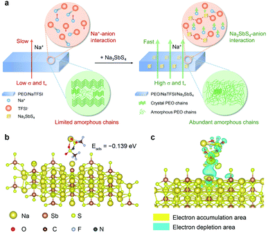
The Na+ conduction in the pure PEO/NaTFSI electrolyte is inferior, owing to the low transference number and poor ionic conductivity.33 As illustrated in Fig. 1a, the Na+ ions and TFSI− anions derived from the dissociation of NaTFSI can migrate simultaneously, leading to a low Na+ transference number. Moreover, the crystallinity of PEO is generally high, meaning that amorphous polymer chains for Na+ conduction are limited. Together with the insufficient dissociation of NaTFSI, the ionic conductivity of PEO/NaTFSI electrolyte will be rather poor. After introducing Na3SbS4, the Na+ transference number can be significantly enhanced because Na3SbS4 can interact with TFSI− anions (which will be verified later) and restrict their migration. Additionally, the interaction between Na3SbS4 and TFSI− anions is beneficial for the dissociation of NaTFSI and, thus, improving the concentration of free Na+ ions in the electrolyte. Moreover, the crystallinity of PEO can be reduced after the addition of Na3SbS4. Therefore, not only the Na+ transference number but also the ionic conductivity can be significantly improved after the introduction of Na3SbS4 into the PEO/NaTFSI electrolyte (Fig. 1a).At first, we used density functional theory (DFT) calculations to study the possible interaction between Na3SbS4 and NaTFSI. Detailed calculation processes can be seen in the ESI.† For NaTFSI, the binding energy between the Na+ ion and TFSI− ion is −4.022 eV, which decreases to −0.456 eV after the addition of Na3SbS4, indicating that Na3SbS4 is helpful for promoting the dissociation of NaTFSI to Na+ and TFSI− ions. The optimized configuration of NaTFSI adsorbed on Na3SbS4 is shown in Fig. 1b. The results demonstrate the existence of an interaction between Na3SbS4 and the TFSI− anion with an adsorption energy of −0.139 eV. Furthermore, the differential charge density of NaTFSI adsorbed on Na3SbS4 was further calculated. As shown in Fig. 1c, the interaction between Na3SbS4 and TFSI− anion is dominated by an electrostatic interaction, which weakens the Na–O bond in NaTFSI and the Sb–S bond in Na3SbS4. In addition, the electron density around Sb increases, which is derived from the interaction between F (of the TFSI− anion) and Sb. The DFT calculations reveal that Na3SbS4 would interact with the TFSI− anion in NaTFSI salt, which is favorable for restricting the migration of TFSI− anions, promoting the dissociation of NaTFSI and, thus, enhancing Na+ transference number and ionic conductivity.
Preparation and characterization of all-solid-state electrolytes
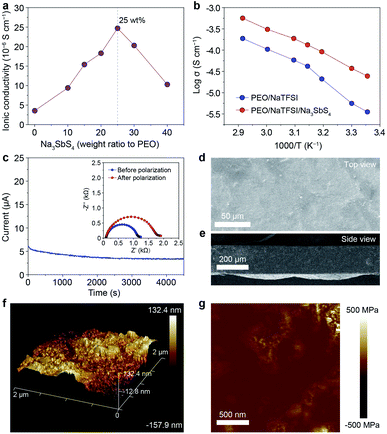
On the basis of the theoretical calculation results, we selected Na3SbS4 as the additive incorporated into the PEO/NaTFSI electrolyte. The Na3SbS4 sample was prepared through a facile aqueous solution method at room temperature. The detailed synthesis process can be seen in the ESI.† The X-ray powder diffraction (XRD) pattern in Fig. S1† demonstrates the successful synthesis of the Na3SbS4 sample, which is consistent with previous works.37 Although some weak extra XRD peaks emerge after the Na3SbS4 sample exposed in air for 24 h, its structure can be fully recovered upon being reheated at 150 °C under vacuum for 10 h (Fig. S1†), implying the relatively good stability of Na3SbS4 in air. As shown in Fig. S2,† the obtained Na3SbS4 mainly consists of nanoparticles, which helps it disperse well in the electrolyte. We further evaluated the ionic conductivity of the obtained Na3SbS4. The result in Fig. S3† indicates that the ionic conductivity of Na3SbS4 is about 1.29 × 10⁻⁴ S cm−1 at room temperature.The PEO-based all-solid-state electrolytes can be prepared through a facile solution casting method (see details in the ESI†). The ionic conductivity of the pristine electrolyte (PEO/NaTFSI) without Na3SbS4 is 3.55 × 10⁻⁶ S cm−1 at room temperature. As the content of Na3SbS4 increases, the ionic conductivity of the electrolyte increases and reaches the highest value of 2.47 × 10⁻⁵ S cm−1 at room temperature when the content of Na3SbS4 is 25 wt% (calculated based on the mass of PEO). Unfortunately, the ionic conductivity of the electrolyte decreases if the content of Na3SbS4 further increases (1.03 × 10⁻⁵ S cm−1 for 40 wt% Na3SbS4, Fig. 2a). Considering that Na3SbS4 can be hardly dissolved in PEO (Fig. S4†), this phenomenon could be attributed to the introduction of excessive interphases within the electrolyte, which is similar to that in polymer/inorganic composite all-solid-state Li+ electrolytes.44 Thus, we selected the electrolyte with 25 wt% Na3SbS4 as the optimal one for further study in the following work.
We then tested the ionic conductivities of the PEO/NaTFSI and PEO/NaTFSI/Na3SbS4 electrolytes at higher temperatures. As shown in Fig. 2b, the ionic conductivity of the PEO/NaTFSI/Na3SbS4 electrolyte can reach 1.33 × 10⁻⁴ and 5.64 × 10⁻⁴ S cm−1 at 45 and 70 °C, respectively, which is far superior than that of the pristine PEO/NaTFSI electrolyte. We further measured the Na+ transference numbers of the two different electrolytes using the method proposed by Bruce et al.45 This method has been widely used to measure the Na+ or Li+ transference number of polymer/inorganic composite all-solid-state electrolytes.27,31,35 The results in Fig. 2c reveal that the Na+ transference number of the PEO/NaTFSI/Na3SbS4 electrolyte is about 0.49, which is much higher than that of the PEO/NaTFSI electrolyte (0.20, Fig. S5†). The enhanced transference number after introducing Na3SbS4 can be ascribed to the electrostatic interaction between Na3SbS4 and the TFSI− anion, which will be discussed in detail later.
Subsequently, we further characterized the electrolytes by various approaches. The scanning electron microscopy (SEM) image of the PEO/NaTFSI/Na3SbS4 electrolyte in Fig. 2d indicates the relatively flat surface of the electrolyte film. The corresponding elemental mappings in Fig. S6† reveal that C, N, O, F, Na, Sb, and S are distributed uniformly in the PEO/NaTFSI/Na3SbS4 composite electrolyte. The cross-sectional SEM image of the PEO/NaTFSI/Na3SbS4 electrolyte in Fig. 2e implies that the thickness of the electrolyte is about 100–200 μm. In addition, atomic force microscopy (AFM) was used to characterize the electrolytes. The AFM topography image with a 3D view in Fig. 2f also indicates the smooth surface of the PEO/NaTFSI/Na3SbS4 electrolyte with a surface roughness of about 39.3 nm. Moreover, the map of Young’s modulus of the PEO/NaTFSI/Na3SbS4 electrolyte is shown in Fig. 2g, and the average Young’s modulus is 47.8 MPa. These results reveal that the mechanical properties of the PEO/NaTFSI/Na3SbS4 electrolyte are far superior to those of the pristine PEO/NaTFSI electrolyte (the average Young’s modulus is only 2.4 MPa, as shown in Fig. S7†). Moreover, the Young’s modulus and surface roughness of the PEO/NaTFSI/Na3SbS4 electrolyte are comparable to those of other reported polymer-based all-solid-state electrolytes for sodium batteries (Table S1†). The good mechanical properties of the PEO/NaTFSI/Na3SbS4 electrolyte are favorable for inhibiting Na dendrite growth. In addition, the weight loss of the PEO/NaTFSI/Na3SbS4 electrolyte starts at about 345 °C, indicating the good thermal stability of the electrolyte (Fig. S8†). The linear sweep voltammetry of the PEO/NaTFSI/Na3SbS4 electrolyte in Fig. S9† implies that the electrolyte exhibits a relatively wide electrochemical stability window with an anodic decomposition potential of about 3.7 V (vs. Na+/Na). Compared with most of the reported polymer-based all-solid-state electrolytes for sodium batteries, our prepared PEO/NaTFSI/Na3SbS4 electrolyte exhibits superior comprehensive performance (Table S2†).
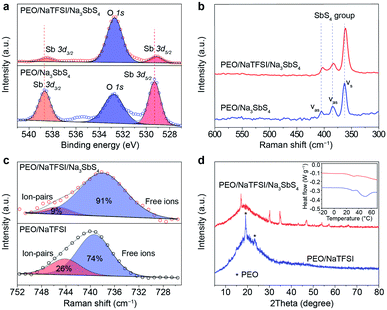
Then, we tried to reveal the possible interactions between components in the electrolyte by spectral and other techniques (Fig. 3). The Sb 3d X-ray photoelectron spectrometry (XPS) spectra of PEO/Na3SbS4 and PEO/NaTFSI/Na3SbS4 electrolyte are shown in Fig. 3a. The binding energies of Sb 3d5/2 and Sb 3d3/2 in PEO/Na3SbS4 are located at 529.3 and 538.7 eV, respectively.46 After introducing NaTFSI, these binding energies negatively shift to 529.1 and 538.5 eV, respectively, indicating that the electron density around Sb increases, which is in good agreement with the DFT calculation results (Fig. 1c). Moreover, the characteristic Raman shifts of the stretching vibration of the SbS4 group in PEO/Na3SbS4 were observed at 405, 384, and 363 cm−1.37 After the introduction of NaTFSI, these peaks negatively move to 403, 383, and 361 cm−1, respectively (Fig. 3b), implying that the Sb–S bonds of Na3SbS4 are weakened, owing to the interaction between the TFSI− anions and Na3SbS4. Overall, the XPS and Raman spectra results unambiguously verify the existence of an interaction between TFSI− anions and Na3SbS4, which is highly consistent with the DFT calculation results in Fig. 1c.
According to previous works, the dissociation behavior of NaTFSI can be detected via the S–N–S stretching vibration in the Raman spectra.47–50 As shown in Fig. 3c, for the PEO/NaTFSI electrolyte, the Raman shifts located at 739 and 744 cm−1 correspond to the TFSI− anions in the free and ion-pair states, respectively. The fitting results reveal that the dissociation ratio of NaTFSI is about 74% in the PEO/NaTFSI electrolyte, which increases to 91% in the PEO/NaTFSI/Na3SbS4 electrolyte. The enhanced dissociation ratio of NaTFSI can be ascribed to the interaction between the TFSI− anions and Na3SbS4, which is also consistent with the DFT calculation results.
In addition, the XRD patterns of PEO/NaTFSI electrolyte and PEO/NaTFSI/Na3SbS4 electrolyte are shown in Fig. 3d. The results reveal that the crystallinity of PEO decreases after the addition of Na3SbS4. In other words, the amorphous phase formed by the polymer chains increases, which is beneficial for Na+ migration and, thus, improving ionic conductivity.51 This result is also confirmed by differential scanning calorimetry (DSC). As shown in the inset of Fig. 3d, the melting temperature of PEO obviously decreases in the PEO/NaTFSI/Na3SbS4 electrolyte when compared with that in the PEO/NaTFSI electrolyte, implying the decreased crystallinity of PEO after introducing Na3SbS4.
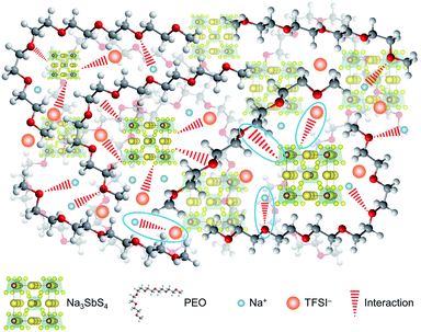
On the basis of the theoretical and experimental results, we can get a deep understanding on the structure of the PEO/NaTFSI/Na3SbS4 electrolyte. As illustrated in Fig. 4, Na3SbS4 in the electrolyte can interact with TFSI− anions, improving the Na+ transference number and promoting the dissociation of NaTFSI. Moreover, Na3SbS4 is Na+ ionically conducting and can decrease the crystallinity of PEO, resulting in enhanced ionic conductivity. In addition, the main functions of NaTFSI and PEO are providing Na+ ions and being responsible for Na+ migration (through the interaction between Na+ and PEO), respectively.
Na plating/stripping behavior in symmetric cells
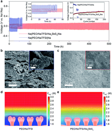
After achieving a thorough insight into the structure of the PEO/NaTFSI/Na3SbS4 electrolyte, we started to investigate its application in all-solid-state batteries at 45 °C. The reason why the batteries were tested under heating is that the ionic conductivity of the electrolytes and the electrode/electrolyte interface are not good enough to support the batteries operating well at room temperature. We first studied the Na plating/stripping behavior in Na|Na symmetric cells with the electrolytes. Fig. 5a shows the cycling performance of different symmetric cells at 50 μA cm−2. The initial total overpotential (the sum of the charge and discharge overpotentials) of the symmetric cell with the PEO/NaTFSI electrolyte is much higher than that with the PEO/NaTFSI/Na3SbS4 electrolyte (511 vs. 153 mV). Moreover, the symmetric cell with the PEO/NaTFSI/Na3SbS4 electrolyte exhibits superior cycling stability with a small overpotential increase of 109 mV after 500 h. In contrast, the symmetric cell with the PEO/NaTFSI electrolyte can only run for about 41 h, followed by short circuiting. We further evaluated the Na plating/stripping performance of Na|Na symmetric cells with different electrolytes at a higher current density (0.1 mA cm−2). As shown in Fig. S10,† both the cycling performance and overpotential of Na|Na symmetric cells at 0.1 mA cm−2 with the PEO/NaTFSI/Na3SbS4 electrolyte are superior than those with the PEO/NaTFSI electrolyte. Moreover, compared with other reported polymer-based all-solid-state Na|Na symmetric cells, our fabricated symmetric cells with the PEO/NaTFSI/Na3SbS4 electrolyte show moderate polarization even at a relatively low temperature of 45 °C (Table S3†).Then, we used SEM to observe the surface of the Na metal after cycling in different symmetric cells. The result in Fig. 5b shows that obvious Na dendrites emerged after cycling in the symmetric cell with the PEO/NaTFSI electrolyte. In contrast, the surface of cycled Na metal in the symmetric cell with the PEO/NaTFSI/Na3SbS4 electrolyte was smooth and no dendrites were found (Fig. 5c). Furthermore, we used XPS to investigate the solid electrolyte interphase (SEI) on the Na electrode after stripping/plating in symmetric cells with different electrolytes. The XPS survey and F 1s spectra show that the ratio of generated NaF among all the SEI species on the Na electrode after stripping/plating with the PEO/NaTFSI/Na3SbS4 electrolyte is lower than that with PEO/NaTFSI electrolyte (Fig. S11†), implying that fewer TFSI− anions participate in the solvation and, thus, the formation of the SEI in the PEO/NaTFSI/Na3SbS4 electrolyte system. This phenomenon can be attributed to the weakened interaction between Na+ and TFSI−, as well as the lower mobility of TFSI− after introducing Na3SbS4.
To further understand the underlying reason for the high cycling stability of the symmetric cells with the PEO/NaTFSI/Na3SbS4 electrolyte, we used the finite element method (FEM) to simulate the Na plating and Na+ distribution behavior in different electrolytes (Fig. S12†). The detailed simulation parameters can be seen in Table S4.† As shown in Fig. 5d, after deposition under 0.1 mA cm−2 for 9600 s, a higher degree of Na+ depletion near the electrode surface can be observed with the PEO/NaTFSI electrolyte, and the Na+ flux for deposition is mainly concentrated on the tips of the electrode surface where more Na+ ions are available.52–54 In this situation, the tip-growing of the Na deposition layer is more favored and finally leads to a branched deposition layer in the final state. In contrast, the Na+ depletion phenomenon is largely alleviated in the PEO/NaTFSI/Na3SbS4 electrolyte. Thus, Na+ ions are more available over the electrode surface, which means that the Na+ flux for deposition is more evenly distributed (Fig. 5e). Through observing the detailed deposition process (Video S1†), it could be discovered that the Na+ depletion layer is built right after the deposition began in the PEO/NaTFSI electrolyte and, thus, the major part of deposition process is proceeded under a Na+ depletion situation, leading to the tip-growing pattern. On the contrary, in the PEO/NaTFSI/Na3SbS4 electrolyte, alleviated Na+ depletion could reasonably favor a more uniform Na deposition layer (Video S1†). The FEM simulation results demonstrate the advantages of the PEO/NaTFSI/Na3SbS4 electrolyte with a high transference number and high ionic conductivity toward stable Na plating/stripping.
Fabrication and performance of all-solid-state Na–PTCDA batteries
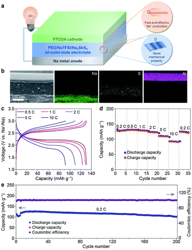
After revealing the multiple advantages of the PEO/NaTFSI/Na3SbS4 electrolyte, we investigated the applications of this electrolyte in all-solid-state Na batteries with organic PTCDA as the cathode. The schematic diagram of the Na–PTCDA battery is shown in Fig. 6a. The structure of the battery was confirmed by the cross-sectional SEM image and elemental mappings of Na, S, and Al. As shown in Fig. 6b, the all-solid-state battery exhibits a three-layer structure, corresponding to the Na metal anode, PEO/NaTFSI/Na3SbS4 electrolyte, and PTCDA cathode. In addition, high-resolution SEM images in Fig. S13† indicate the compact contact between the electrolyte and cathode, and also between the electrolyte and anode.We further studied the electrochemical performance of the all-solid-state Na–PTCDA batteries with the PEO/NaTFSI/Na3SbS4 electrolyte at 45 °C. The voltage profiles at different current rates in Fig. 6c imply the highly reversible redox processes of the batteries. As shown in Fig. 6d, the PTCDA cathode in all-solid-state batteries can deliver 130, 131, 129, 124, 110, and 92 mA h g−1 at current rates of 0.2, 0.5, 1, 2, 5, and 10C (1C = 137 mA g−1, the value of the theoretical capacity of PTCDA), respectively, meaning that about 71% capacity can be retained even at a high rate of 10C (compared with the capacity at 0.2C). When the current rate returns to 0.2C, most of the capacity can be recovered. The superior rate performance could be mainly attributed to the large Na+ transference number and high ionic conductivity of the PEO/NaTFSI/Na3SbS4 electrolyte, as well as the favorable electrode/electrolyte interface. In contrast, with the PEO/NaTFSI electrolyte, the discharge capacities of the PTCDA cathode are only 116, 114, 110, 106, 92, and 75 mA h g−1 at current rates of 0.2, 0.5, 1, 2, 5, and 10C, respectively (Fig. S14†).
Similar to most organic electrode materials, PTCDA, with a relatively low molecular weight, shows high dissolution in organic liquid electrolyte and thereby poor cycling stability.55–57 As shown in Fig. S15†, the capacity retention of PTCDA in a common 1 M NaPF6/diglyme electrolyte is only 63% after 60 cycles. In contrast, PTCDA shows remarkably enhanced cycling performance with the all-solid-state PEO/NaTFSI/Na3SbS4 electrolyte. The capacity maintains 101 mA h g−1 after 200 cycles at 0.2C, corresponding to a high capacity retention of 84% (Fig. 6e). To form superior interfacial contact during the cycles, the rates of the initial 5 cycles were set as 0.1C for activation. The high capacity retention could be mainly ascribed to the limited dissolution of PTCDA in the PEO/NaTFSI/Na3SbS4 electrolyte. Compared with other reported Na batteries using polymer-based all-solid-state electrolytes, our fabricated Na–PTCDA batteries show superior rate performance and cycling stability (Table S5†). Overall, the good comprehensive electrochemical performance of the Na–PTCDA batteries and Na|Na symmetric cells demonstrates the superiority of the all-solid-state PEO/NaTFSI/Na3SbS4 electrolyte, implying its great promise for wide applications.
Conclusions
In summary, we have successfully achieved a high-performance all-solid-state PEO-based electrolyte via the introduction of Na3SbS4. The combination of theoretical calculations and experimental studies reveals that there is a strong electrostatic interaction between Na3SbS4 and TFSI− anions, resulting in a large Na+ transference number (0.49), high ionic conductivity (1.33 × 10⁻⁴ S cm−1 at 45 °C), and good mechanical properties (average Young’s modulus: 47.8 MPa) for PEO/NaTFSI/Na3SbS4 electrolyte. Moreover, the electrolyte can largely alleviate Na+ depletion near the electrode surface in symmetric cells, bringing about stable and dendrite-free Na plating/stripping behavior for 500 h. Furthermore, the fabricated Na–PTCDA batteries show good cycling stability with a high capacity retention of 84% after 200 cycles, as well as superior rate performance (up to 10C). This work paves the way to construct a high-performance all-solid-state electrolyte for sodium batteries.Data availability
The data that support the findings of this study are available within the article and its ESI,† or from the corresponding author on reasonable request.Author contributions
Y. Lu and L. Li contributed equally to this work. J. Chen and Y. Lu proposed the idea of this work and designed the experiments. Y. Lu and L. Li carried out the preparation, characterization, and electrochemical measurements. Q. Zhang organized the figures. Y. Cai and Y. Ni performed the finite element method simulations and density functional theory calculations, respectively. J. Chen and Y. Lu wrote the manuscript. The manuscript was discussed and revised by all authors.Conflicts of interest
There are no conflicts of interest to declare.Acknowledgements
This work was financially supported by the National Natural Science Foundation of China (22109075, 21835004 and 22020102002), the National Key R&D Program of China (2017YFA0206700), the 111 Project from the Ministry of Education of China (B12015), the Frontiers Science Center for New Organic Matter of Nankai University (63181206), and the Haihe Laboratory of Sustainable Chemical Transformations. The calculations in this work were performed at the TianHe-1(A), National Supercomputer Center in Tianjin.Notes and references
- C. Vaalma, D. Buchholz, M. Weil and S. Passerini, Nat. Rev. Mater., 2018, 3, 18013 CrossRef.
- A. Schneemann, R. Dong, F. Schwotzer, H. Zhong, I. Senkovska, X. Feng and S. Kaskel, Chem. Sci., 2021, 12, 1600–1619 RSC.
- H. S. Hirsh, Y. Li, D. H. S. Tan, M. Zhang, E. Zhao and Y. S. Meng, Adv. Energy Mater., 2020, 10, 2001274 CrossRef CAS.
- E. M. Miner and M. Dincă, Philos. Trans. R. Soc., A, 2019, 377, 20180225 CrossRef CAS PubMed.
- Y.-F. Zhu, Y. Xiao, S.-X. Dou, Y.-M. Kang and S.-L. Chou, eScience, 2021, 1, 13–27 CrossRef.
- W. Zhang, J. Lu and Z. Guo, Mater. Today, 2021, 50, 400–417 CrossRef CAS.
- Y.-B. Niu, Y.-J. Guo, Y.-X. Yin, S.-Y. Zhang, T. Wang, P. Wang, S. Xin and Y.-G. Guo, Adv. Mater., 2020, 32, 2001419 CrossRef CAS PubMed.
- J.-J. Kim, K. Yoon, I. Park and K. Kang, Small Methods, 2017, 1, 1700219 CrossRef.
- Y. Lu, L. Li, Q. Zhang, Z. Niu and J. Chen, Joule, 2018, 2, 1747–1770 CrossRef CAS.
- Y. Deng, C. Eames, L. H. B. Nguyen, O. Pecher, K. J. Griffith, M. Courty, B. Fleutot, J.-N. Chotard, C. P. Grey, M. S. Islam and C. Masquelier, Chem. Mater., 2018, 30, 2618–2630 CrossRef CAS.
- L. Ran, M. Li, E. Cooper, B. Luo, I. Gentle, L. Wang and R. Knibbe, Energy Storage Mater., 2021, 41, 8–13 CrossRef.
- A. Hayashi, N. Masuzawa, S. Yubuchi, F. Tsuji, C. Hotehama, A. Sakuda and M. Tatsumisago, Nat. Commun., 2019, 10, 5266 CrossRef CAS PubMed.
- K. Niitani, S. Ushiroda, H. Kuwata, H. N. Ohata, Y. Shimo, M. Hozumi, T. Matsunaga and S. Nakanishi, ACS Energy Lett., 2022, 7, 145–149 CrossRef CAS.
- P. Bonnick, K. Niitani, M. Nose, K. Suto, T. S. Arthur and J. Muldoon, J. Mater. Chem. A, 2019, 7, 24173–24179 RSC.
- G. J. Rees, D. S. Jolly, Z. Ning, T. J. Marrow, G. E. Pavlovskaya and P. G. Bruce, Angew. Chem., Int. Ed., 2021, 60, 2110–2115 CrossRef CAS PubMed.
- X. Yu and A. Manthiram, Matter, 2019, 1, 439–451 CrossRef.
- Z. Zhang, P.-N. Roy, H. Li, M. Avdeev and L. F. Nazar, J. Am. Chem. Soc., 2019, 141, 19360–19372 CrossRef CAS PubMed.
- F. Sun, L. Duchêne, M. Osenberg, S. Risse, C. Yang, L. Chen, N. Chen, Y. Huang, A. Hilger, K. Dong, T. Arlt, C. Battaglia, A. Remhof, I. Manke and R. Chen, Nano Energy, 2021, 82, 105762 CrossRef CAS.
- R. Mohtadi and S.-I. Orimo, Nat. Rev. Mater., 2017, 2, 16091 CrossRef.
- C. Zhao, L. Liu, X. Qi, Y. Lu, F. Wu, J. Zhao, Y. Yu, Y.-S. Hu and L. Chen, Adv. Energy Mater., 2018, 8, 1703012 CrossRef.
- Y. Lu, Y. Cai, Q. Zhang, L. Liu, Z. Niu and J. Chen, Chem. Sci., 2019, 10, 4306–4312 RSC.
- X. Judez, H. Zhang, C. Li, J. A. González-Marcos, Z. Zhou, M. Armand and L. M. Rodriguez-Martinez, J. Phys. Chem. Lett., 2017, 8, 1956–1960 CrossRef CAS PubMed.
- Z. Xue, D. He and X. Xie, J. Mater. Chem. A, 2015, 3, 19218–19253 RSC.
- C.-Z. Zhao, X.-Q. Zhang, X.-B. Cheng, R. Zhang, R. Xu, P.-Y. Chen, H.-J. Peng, J.-Q. Huang and Q. Zhang, Proc. Natl. Acad. Sci. U. S. A., 2017, 114, 11069–11074 CrossRef CAS PubMed.
- Q. Ma, J. Liu, X. Qi, X. Rong, Y. Shao, W. Feng, J. Nie, Y.-S. Hu, H. Li, X. Huang, L. Chen and Z. Zhou, J. Mater. Chem. A, 2017, 5, 7738–7743 RSC.
- F. Gebert, J. Knott, R. Gorkin III, S.-L. Chou and S.-X. Dou, Energy Storage Mater., 2021, 36, 10–30 CrossRef.
- M. L. Lehmann, G. Yang, D. Gilmer, K. S. Han, E. C. Self, R. E. Ruther, S. Ge, B. Li, V. Murugesan, A. P. Sokolov, F. M. Delnick, J. Nanda and T. Saito, Energy Storage Mater., 2019, 21, 85–96 CrossRef.
- Y. L. Ni’mah, M.-Y. Cheng, J. H. Cheng, J. Rick and B.-J. Hwang, J. Power Sources, 2015, 278, 375–381 CrossRef.
- Z. Zhang, Q. Zhang, C. Ren, F. Luo, Q. Ma, Y.-S. Hu, Z. Zhou, H. Li, X. Huang and L. Chen, J. Mater. Chem. A, 2016, 4, 15823–15828 RSC.
- Z. Wang, L. Yang, J. Liu, Y. Song, Q. Zhao, K. Yang and F. Pan, ACS Appl. Mater. Interfaces, 2020, 12, 48677–48683 CrossRef CAS PubMed.
- T. Zhu, X. Dong, Y. Liu, Y.-G. Wang, C. Wang and Y.-Y. Xia, ACS Appl. Energy Mater., 2019, 2, 5263–5271 CrossRef CAS.
- X. Yu, L. Xue, J. B. Goodenough and A. Manthiram, ACS Mater. Lett., 2019, 1, 132–138 CrossRef CAS.
- J.-F. Wu, Z.-Y. Yu, Q. Wang and X. Guo, Energy Storage Mater., 2020, 24, 467–471 CrossRef.
- X. Xu, Y. Li, J. Cheng, G. Hou, X. Nie, Q. Ai, L. Dai, J. Feng and L. Ci, J. Energy Chem., 2020, 41, 73–78 CrossRef.
- C. Ma, K. Dai, H. Hou, X. Ji, L. Chen, D. G. Ivey and W. Wei, Adv. Sci., 2018, 5, 1700996 CrossRef PubMed.
- A. Banerjee, K. H. Park, J. W. Heo, Y. J. Nam, C. K. Moon, S. M. Oh, S.-T. Hong and Y. S. Jung, Angew. Chem., Int. Ed., 2016, 55, 9634–9638 CrossRef CAS PubMed.
- H. Wang, Y. Chen, Z. D. Hood, G. Sahu, A. S. Pandian, J. K. Keum, K. An and C. Liang, Angew. Chem., Int. Ed., 2016, 55, 8551–8555 CrossRef CAS PubMed.
- L. Zhang, D. Zhang, K. Yang, X. Yan, L. Wang, J. Mi, B. Xu and Y. Li, Adv. Sci., 2016, 3, 1600089 CrossRef PubMed.
- H. Wan, W. Weng, F. Han, L. Cai, C. Wang and X. Yao, Nano Today, 2020, 33, 100860 CrossRef CAS.
- S. Zhang, Y. Zhao, F. Zhao, L. Zhang, C. Wang, X. Li, J. Liang, W. Li, Q. Sun, C. Yu, J. Luo, K. Doyle-Davis, R. Li, T.-K. Sham and X. Sun, Adv. Funct. Mater., 2020, 30, 2001118 CrossRef CAS.
- H. Gamo, N. H. H. Phuc, R. Matsuda, H. Muto and A. Matsuda, Mater. Today Energy, 2019, 13, 45–49 CrossRef.
- P. Hu, Y. Zhang, X. Chi, K. K. Rao, F. Hao, H. Dong, F. Guo, Y. Ren, L. C. Grabow and Y. Yao, ACS Appl. Mater. Interfaces, 2019, 11, 9672–9678 CrossRef CAS PubMed.
- B. Tang, Y. Zhao, Z. Wang, S. Chen, Y. Wu, Y. Tseng, L. Li, Y. Guo, Z. Zhou and S.-H. Bo, eScience, 2021 DOI:10.1016/j.esci.2021.12.001.
- L. Chen, Y. Li, S.-P. Li, L.-Z. Fan, C.-W. Nan and J. B. Goodenough, Nano Energy, 2018, 46, 176–184 CrossRef CAS.
- J. Evans, C. A. Vincent and P. G. Bruce, Polymer, 1987, 28, 2324–2328 CrossRef CAS.
- T. Honma, R. Sato, Y. Benino, T. Komatsu and V. Dimitrov, J. Non-Cryst. Solids, 2000, 272, 1–13 CrossRef CAS.
- Y. Yamada, K. Furukawa, K. Sodeyama, K. Kikuchi, M. Yaegashi, Y. Tateyama and A. Yamada, J. Am. Chem. Soc., 2014, 136, 5039–5046 CrossRef CAS PubMed.
- N. Wu, P.-H. Chien, Y. Qian, Y. Li, H. Xu, N. S. Grundish, B. Xu, H. Jin, Y.-Y. Hu, G. Yu and J. B. Goodenough, Angew. Chem., Int. Ed., 2020, 59, 4131–4137 CrossRef CAS PubMed.
- R. Rojaee, S. Cavallo, S. Mogurampelly, B. K. Wheatle, V. Yurkiv, R. Deivanayagam, T. Foroozan, M. G. Rasul, S. Sharifi-Asl, A. H. Phakatkar, M. Cheng, S.-B. Son, Y. Pan, F. Mashayek, V. Ganesan and R. Shahbazian-Yassar, Adv. Funct. Mater., 2020, 30, 1910749 CrossRef CAS.
- J. Tan, X. Ao, A. Dai, Y. Yuan, H. Zhuo, H. Lu, L. Zhuang, Y. Ke, C. Su, X. Peng, B. Tian and J. Lu, Energy Storage Mater., 2020, 33, 173–180 CrossRef.
- K. Pan, L. Zhang, W. Qian, X. Wu, K. Dong, H. Zhang and S. Zhang, Adv. Mater., 2020, 32, 2000399 CrossRef CAS PubMed.
- J. Xiao, Science, 2019, 366, 426–427 CrossRef CAS PubMed.
- M. C. Ma, G. Li, X. Chen, L. A. Archer and J. Wan, Sci. Adv., 2021, 7, eabf6941 CrossRef CAS PubMed.
- X. Xu, Y. Liu, J.-Y. Hwang, O. O. Kapitanova, Z. Song, Y.-K. Sun, A. Matic and S. Xiong, Adv. Energy Mater., 2020, 10, 2002390 CrossRef CAS.
- S. Cao, H. Zhang, Y. Zhao and Y. Zhao, eScience, 2021, 1, 28–43 CrossRef.
- L. Sieuw, A. Jouhara, É. Quarez, C. Auger, J.-F. Gohy, P. Poizot and A. Vlad, Chem. Sci., 2019, 10, 418–426 RSC.
- W. Luo, M. Allen, V. Raju and X. Ji, Adv. Energy Mater., 2014, 4, 1400554 CrossRef.
Footnotes |
| † Electronic supplementary information (ESI) available: Experimental section, computational details, and additional figures, tables and video, as mentioned in the text. See DOI: 10.1039/d1sc06745a |
| ‡ These authors contributed equally to this work. |
| This journal is © The Royal Society of Chemistry 2022 |

