A self-healing polymerized-ionic-liquid-based polymer electrolyte enables a long lifespan and dendrite-free solid-state Li metal batteries at room temperature†
Xiujing
Lin
a,
Shiyuan
Xu
a,
Yuqi
Tong
a,
Xinshuang
Liu
a,
Zeyu
Liu
a,
Pan
Li
a,
Ruiqing
Liu
a,
Xiaomiao
Feng
 a,
Li
Shi
*a and
Yanwen
Ma
 *ab
*ab
aKey Laboratory for Organic Electronics and Information Displays (KLOEID) & Institute of Advanced Materials (IAM), Jiangsu Key Laboratory for Biosensors, Jiangsu National Synergetic Innovation Center for Advanced Materials (SICAM), Nanjing University of Posts and Telecommunications, Nanjing, Jiangsu 210023, China. E-mail: iamlshi@njupt.edu.cn; iamywma@njupt.edu.cn
bSuzhou Vocational Institute of Industrial Technology, 1 Zhineng Avenue, Suzhou International Education Park, Suzhou 215104, China
First published on 19th December 2022
Abstract
The implementation of high-safety Li metal batteries (LMBs) needs more stable and safer electrolytes. The solid-state electrolytes (SSEs) with their advantageous properties stand out for this purpose. However, low Li/electrolyte interfacial instability and uncontrolled Li dendrites growth trigger unceasing breakage of the solid electrolyte interphase (SEI), leading to fast capacity degradation. In response to these shortcomings, a new type of polymer electrolyte with self-healing capacity is introduced by grafting ionic liquid chain units into the backbones of polymers, which inherits the chemical inertness against the Li anode, allowing high Li+ transport, wide electrochemical window, and self-healing traits. Benefiting from the strong external H-bonding interactions, the obtained polymer electrolyte can spontaneously reconstruct dendrite-induced defects and fatigue crack growth at the Li/electrolyte interface, and, in turn, help tailor Li deposition. Owing to the resilient Li/electrolyte interface and dendrite-free Li plating, the equipped Li|LFP batteries display a high initial specific capacity of 134.7 mA h g−1, rendering a capacity retention of 91.2% after 206 cycles at room temperature. The new polymer electrolyte will undoubtedly bring inspiration for developing practical LMBs with highly improved safety and interfacial stability.
New conceptsLow Li/electrolyte interfacial instability and uncontrolled growth of lithium dendrites trigger unceasing breakage of the solid electrolyte interphase (SEI) and impede the practical application of solid-state electrolytes. Herein, we introduce a self-healing polymerized-ionic-liquid-based polymer electrolyte by grafting ionic liquid chain units into the backbones of polymers. With this strategy, the obtained polymer inherits the dimensional stability and mechanical durability of polymers, while retaining the traits of ionic liquids. In response to the designability of ionic liquid monomers, specific groups conducive to hydrogen bonding are adopted to impart the self-healing capability to the polymer. This characteristic allows it to spontaneously reconstruct dendrite-induced defects at the Li/electrolyte interface, and, in turn, tailor Li deposition. With the synthesized polymer electrolyte, the solid-state Li|LiFePO4 batteries deliver the best in-class cyclical stability at room temperature. |
1. Introduction
Given the high specific capacity, low redox potential, and low atomic weight, the Li metal anodes-based secondary batteries have long remained on research agendas.1,2 Unfortunately, the safety hazards associated with the flammable and leaky organic liquid electrolytes (OLE) utilized in conventional Li metal batteries (LMBs) impede their large-scale applications. Moreover, the direct parasitic reaction between organic liquid electrolytes and active Li anodes depletes the electrolytes, thicken the electrolyte/anode interphase, and ultimately brings about premature battery failure. Likewise, the uncontrolled Li dendritic generation throughout the cycling process may pierce the brittle separator, inducing internal short circuits and battery failure.2–9To address such challenges, a variety of strategies, including flame-retardant additives, artificial in/ex situ solid electrolyte interphase (SEI), and the design of structured solid-state electrolytes (SSEs), have been utilized.10,11 As an alternative to the organic liquid electrolyte, the SSE is considered more promising for safe energy storage owing to its inherent non-flammability and robust mechanical properties, which plays a pivotal role in restraining Li dendrites. Generally, SSEs can be mainly divided into two major types: inorganic ion-conducting ceramics and organic polymers (namely solid-state polymer electrolytes (SPEs)).9–12
Compared with inorganic SSEs, SPEs exhibit overwhelming advantages in flexibility and can retain relatively close adhesion to Li anodes during cycling, which alleviates void generation at the electrolyte/anode interface. Polymer matrices, including poly(methyl methacrylate) (PMMA), poly(ethylene oxide) (PEO), poly(ethylene glycol) diacrylate (PEGDA), polyacrylonitrile (PAN), poly(vinylidene fluoride)-co-hexafluoropropylene (PVDF-HFP) and so on have been investigated to date.13–16 However, all of these polymers show inadequate room-temperature ionic conductivity to enable long-term cycling. Incorporating plasticizers, such as carbonates, esters, ethers, and ionic liquids into polymer electrolytes, is effective in elevating ionic conductivity at ambient temperature, while maintaining the toughness of polymers. Ionic liquids (ILs), which are composed of organic cations and inorganic or organic anions, have rekindled an interest due to their unique properties, such as incombustibility, non-volatility, high ionic conductivity, and high thermal/electrochemical consistency.17–23 Nevertheless, the adoption of ILs always sacrifices the mechanical capacities of polymers, such as strength and stretchability.
With the above consideration in mind, we reasoned that grafting ionic liquid chain units into the backbones of polymers would inherit the dimensional stability and mechanical durability of polymers without losing the traits of ILs. Based on the designability of ILs, designing of rational molecular structure, e.g. adopting a specific group conducive to hydrogen bonding, is an efficacious strategy to endow the polymers with unique properties, such as thermal stability, hydrophobicity, and self-healing. Particularly for remedying the dendrite-induced defects and fatigue crack growth at the Li/electrolyte interface, a self-healing polymer can eliminate crack propagation spontaneously, reduce explosion hazard, and thus, prolong the lifespan of LMBs.24 Arumugam et al. explored a self-healing polymer electrolyte with 1-allyl-3-methylimidazolium bis(trifluoromethanesulfonyl)imide (AMIMTFSI) and MMA as backbone and EMIFTFSI as the ionic liquids filler. Benefitting from the quick self-healing ability, the solid polymer electrolyte exhibits high compatibility with Li metal.25 Guo and co-workers designed a polymer electrolyte by applying 2-(3-(6-methyl-4-oxo-1,4-dihydropyrimidin-2-yl)ureido) ethyl methacrylate (UPyMA) as the self-healing units, which certainly contributed to the establishment of compact Li/electrolyte interface, and therefore, aided in repairing interfacial flaws.26 Through two PEO networks crosslinked by reversible disulfide and imine bonds, the Zhang group synthesized a self-healable solid polymer electrolyte. The Li|LiFePO4 batteries assembled based on the electrolyte described above deliver a capacity retention of 88.4% over 300 cycles.27
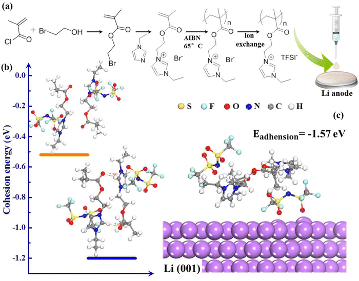
In this work, we introduce a new type of polymer electrolyte by grafting ionic liquid chain units (EMIM+) into the backbones of polymers (PMMA) as presented in Fig. 1(a). From the design perspective, PMMA is used as the matrix of electrolyte because of its chemical stability towards Li, which endows the novel polymer electrolyte with wide electrochemical window.28 The EMIM+ facilitates superior cationic solvation and serves as an H-bonding donor, which could generate hydrogen bonds with oxygen-containing groups of PMMA (Fig. 1(b)),29,30 making the polymer compatible with high Li+ transport and fast self-healing ability. The external H-bonding interactions can spontaneously reconstruct dendrite-induced defects and fatigue crack growth at the Li/electrolyte interface, thus playing a constructive role in Li dendrite suppression. These peculiarities endow polymerized-ionic-liquid (PIL)-based LMBs with remarkable room-temperature cycling performance, presenting a capacity retention of 91.2% over 206 cycles at 0.5 °C. The self-healing polymer electrolyte provides the inspiration to develop practical LMBs with improved safety and interfacial stability.
2. Results and discussion
The target polymerized-ionic-liquid-based polymer of poly(1-ethyl-3-(2-methacryloyloxy ethyl) imidazolium bis(trifluoromethylsulphonyl)imide) (PEMEImTFSI) was synthesized by reacting N-ethylimidazole with 2-bromoethyl methacrylate, followed by polymerization triggered by AIBN and an anion exchange with TFSI−.31,32 Measurements with 1H and 13C NMR were used to confirm the backbone structure of EMEImBr monomers (Fig. 2(a) and (b)). The synthesis of PIL was completed by using azobisisobutyronitrile (AIBN) at 65 °C via free radical polymerization of C![[double bond, length as m-dash]](https://www.rsc.org/images/entities/char_e001.gif) C bonds on EMEImBr monomers. Fourier-transform infrared spectra (FTIR) measurements are shown in Fig. 2(c), which validate the polymerization of EMEImBr monomers. The peak around 1636 cm−1 in EMEImBr monomers corresponds to the stretching of C
C bonds on EMEImBr monomers. Fourier-transform infrared spectra (FTIR) measurements are shown in Fig. 2(c), which validate the polymerization of EMEImBr monomers. The peak around 1636 cm−1 in EMEImBr monomers corresponds to the stretching of C![[double bond, length as m-dash]](https://www.rsc.org/images/entities/char_e001.gif) C,33,34 and it vanishes after polymerization, suggesting successful polymerization.
C,33,34 and it vanishes after polymerization, suggesting successful polymerization.
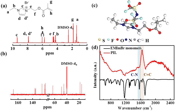 | ||
| Fig. 2 (a) 1H NMR and (b) 13C NMR spectra of EMEImBr monomer, (c) chemical configuration of PIL, (d) FTIR spectra of EMEImBr monomer and PIL polymer matrix. | ||
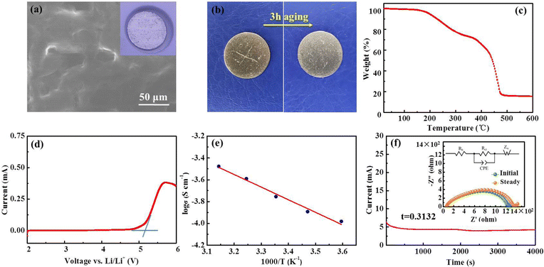
The top-view scanning electron microscopy (SEM) image of the PIL electrolyte (Fig. 3(a)) displays a smooth, flat surface and a homogeneous membrane without phase segregation. Fig. 3(b) shows that the transparent polymer electrolyte membrane can spontaneously self-heal within 3 h after being cut at room temperature; this healing is motivated by the external H-bond interactions. First-principles density functional theory (DFT) demonstrates that intermolecular H-bonding interaction occurs between C–H of the imidazolium ring and the oxygen atom of the carbonyl group (Fig. 1(b)). According to previous literature, H2, H4, and H5 protons of imidazolium rings are H-bonding donors, which generate a hydrogen bond with other molecules, and thus, account for fast self-healing ability.30 Furthermore, the high interfacial adhesive energy at the interface between the Li anode and PIL membrane also improves the self-healing capacity (Fig. 1(c)).
To evaluate the thermal stability of the PIL membrane, thermogravimetric analysis (TGA) was conducted. The membrane exhibits thermal endurance up to 190 °C (Fig. 3(c)), which is superior to conventional organic liquid electrolytes with points of flammability near ambient temperature.22,35 The electrochemical stability of the PIL electrolyte was investigated by the linear sweep voltammetry (LSV) measurement. According to the results in Fig. 3(d), the PIL electrolyte does not encounter electrochemical oxidation until 5.2 V vs. Li/Li+. The temperature effects on the ionic conductivity of the PIL electrolyte are further illustrated in Fig. 3(e). The plots of log![[thin space (1/6-em)]](https://www.rsc.org/images/entities/char_2009.gif) σ versus 1000/T exhibit a linear relationship, which could be well fitted by the Arrhenius equation below:
σ versus 1000/T exhibit a linear relationship, which could be well fitted by the Arrhenius equation below:
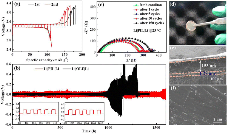
Typically, solid polymer electrolyte membranes were achieved by the solution casting method, involving mass input of organic solvents unfriendly to the environment. The solvent-free hot-pressing technology was put forward to fabricate the crosslinked PEO-based electrolyte, which required additional investment in hot-pressing machines. However, they both belong to ex situ processing methods and could not adhere to the electrode during long-time cycling. An ideal electrolyte membrane depends not only on the novel polymer hosts with high ionic conductivity and electrochemical compatibility towards high-voltage cathodes, but also on the improvement of processing technology. Herein, we fabricate the PIL membrane via an in situ technique that enables close contact and affinity for anodic electrodes. For comparison, the Li|LFP (Li|LiFePO4) batteries with freestanding PIL electrolyte membrane and PIL membrane fabricated on the cathode were assembled and detected in the same condition (Fig. S1, ESI†). In stark contrast to PIL coating on the Li anode, the battery with PIL coating on the cathode encounters battery failure during the 7th cycle. For the battery with a freestanding PIL membrane, capacities above the theoretical value are observed in dozens of circulations associated with electrolyte decomposition, SEI generation,40 followed by a drastic fluctuation in capacity and Coulombic efficiency, manifesting the unstable interface. A galvanostatic intermittent titration technique (GITT) was applied on the Li|LFP batteries with PIL coating on the Li anode at 0.1C to further investigate the Li/electrolyte interface. As presented in Fig. 4(a), a charge/discharge voltage gap of ∼0.12 V between the charge plateau and discharge plateau is achieved, which stands almost still in the following circulation, indicating a stable electrode/electrolyte interface.
Beyond the appropriate ionic conduction, interfacial stability is extraordinarily crucial for Li+ distribution and electrodeposition behavior, which in turn, influences long-term battery operation. A comparative investigation of galvanostatic polarization in Li|Li symmetric batteries was conducted to assess Li stripping/plating reversibility between PIL and organic liquid electrolyte (1 M LiPF6 in EC/DEC/DMC), whereby 1 h charge and discharge intervals under fixed currents were employed. The voltage response over time of the symmetric battery containing PIL and OLE was continuously detected at 0.05 mA cm−2 with 1 h interval per half cycle as presented in Fig. 4(b). The battery displays stationary Li plating/stripping behavior for more than 1600 h, accompanied by only a slight increase in the overpotential after 1500 h, which relates with the mild diminution in the contact surface between Li anode and PIL due to void formation. The voltage profiles in the insets indicate fluid Li plating/stripping with no observable phenomenon of the micro-short circuit, which leads to a sudden change in the voltage and distortion of the voltage curves.22,36,41–43 Meanwhile, the battery cycles stably to 0.2 mA cm−2 in tests at step-varied currents, and the overpotential falls to 0.004 V, when the current density is restored to 0.01 mA cm−2 (Fig. S2, ESI†). The PIL-based symmetric battery exhibits good interfacial stability between Li foils and PIL electrolytes, while presenting high endurance against uneven Li deposition. The point is further validated by electrochemical impedance spectroscopy (EIS) results and SEM data in Fig. 4(c)–(f). As shown in Fig. 4(c), the battery with a PIL membrane delivers a slightly increasing interfacial resistance along with the prolonged cycling number at the beginning, which negligibly varies in the subsequent 40 cycles, indicating the robust contact between the PIL membrane and Li foils throughout the cycling process.34 In terms of the morphology of cycled Li anodes, a truly smooth and flat surface is monitored by adopting PIL electrolyte, with no sign of rough Li dendrites, confirming uniform Li depositing/plating (Fig. 4(f)). The optical photograph and cross-sectional SEM image (Fig. 4(d) and (e)) show the PIL membrane maintains close contact with the Li anode, and a thin uniform Li plating layer with the thickness of ∼27 μm are found along the Li anode. Inversely, massive Li dendrites emerge on the Li anode after long-time cycling, which may pierce into the PP separator for Li|OLE|Li battery, leading to a complete short-circuit (Fig. S2, ESI†).
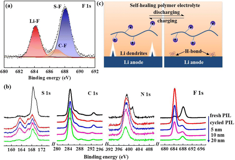
To gain further insight into the inhibition mechanism of Li dendrites by PIL membrane, X-ray photoelectric spectroscopy (XPS) was introduced to further analyze the chemical composition of the interphase layer on the cycled Li anode. The results in Fig. 5(a) show that the F 1s spectrum is composed of Li–F peak (684.2 eV), C–F peak (686.8 eV), and S–F (688.0 eV),22 displaying a high F content of 33.14% in the SEI layer. As the decomposition product of TFSI− anions, the SEI layer with rich LiF not only facilitates the formation of a stabilized interphase, but also induces dendrite-free Li plating owing to its ultrahigh mechanical strength and facile interfacial Li+ ion transport.36,44–46 Given the high reactivity of Li anodes, in-depth XPS measurements were also performed on the PIL membrane after cycling. Depth profiles of representative elements (Fig. 5(b)) demonstrate a mesophase layer with a thickness of 20 nm, which may contribute to stabilizing the Li/electrolyte interface.2,14,47–50 Ordinarily, flaws at the Li/solid-state electrolyte interface result in uneven Li deposition and void formation, deteriorating the Li dendrites generation. As illustrated in Fig. 5(c), benefitting from the self-healing peculiarity, the novel polymer electrolyte not only remains an integrated Li/electrolyte interface, but also spontaneously remedies dendrite-induced voids at the interface, eliminating crack extension and enabling homogenous Li ionic flux.26,36
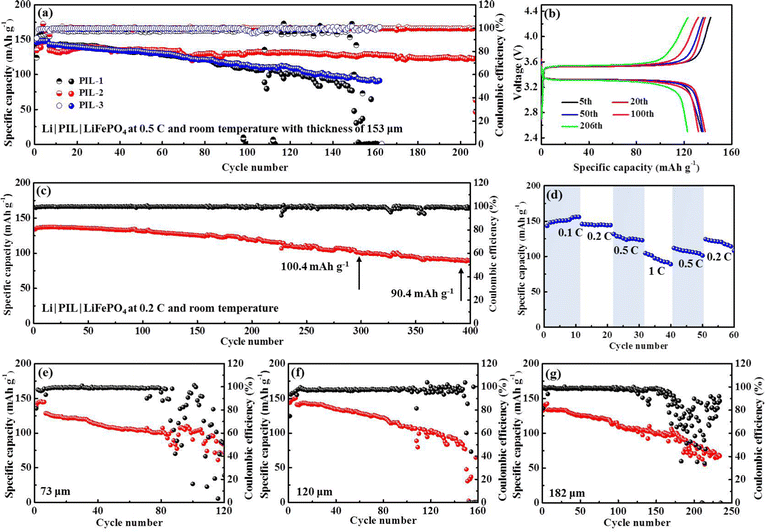
The polymerization degree has a profound impact on the features of PIL electrolytes. A high polymerization degree invests PIL electrolytes with mechanical properties at the cost of ion conductivity. Striking a balance between the two is crucially important. Table S1 (ESI†) summarizes the weight average molecular weight (Mw), number average molecular weight (Mn), and corresponding polydispersity indexes (Mw/Mn) of PIL electrolytes, respectively. Comparison of the diverse molecular weights formed in our synthesis implies that PIL-2 polymer with Mw of 28.418 kDa delivers superior cycling performance (Fig. 6(a)). In detail, an initial discharge specific capacity of 134.7 mA h g−1 is displayed by Li|PIL-2|LFP batteries at room temperature and 0.5C, which slowly fades to 122.9 mA h g−1 after 206 cycles, corresponding to an outstanding capacity retention of 91.2%. According to the typical voltage profiles, the battery shows high levels of reversibility and approximately flat charge/discharge plateaus at 3.54/3.31 V for 206 cycles, associating with the Li/Li+ redox behavior of LiFePO4 (Fig. 6(b)). For the batteries with other PIL polymers, a dramatic capacity decay is observed and a relatively lower discharge specific capacity of ∼100 mA h g−1 is obtained at the end of 150 cycles. A polymer electrolyte membrane consisting of PMMA and EMIMTFSI precursors used to create our PIL polymers is fabricated by the conventional solution-casting method. The results listed in ESI,† Table S2 manifest the non-grafting PMMA/EMIMTFSI electrolyte encounters dramatic capacity fading in the first few circulations. It can be concluded that grafting EMIM+ into the backbones of PMMA polymer exerts positive effects rather than compromising expediting Li stripping/plating processes. When cycling at 0.2C, the discharge specific capacity maintains 118.9 and 90.4 mA h g−1, rendering capacity retention of 88.9% and 67.6% after 200 and 392 cycles, respectively (Fig. 6(c)). In terming of the charge/discharge curves (Fig. S3, ESI†), the battery with PIL membrane presents an extremely flat charge/discharge platform of 3.57/3.32 V. Nevertheless, the voltage gap displays a slightly increasing tendency starting from the 200th cycle. The rate capability of PIL-based Li|LFP batteries was evaluated from 0.1C to 1C at room temperature, as presented in Fig. 6(d). The reversible capacities of 148.9, 144.5, 131.7, and 104.6 mA h g−1 are achieved as the current density boosting from 0.1C to 1C. When the current density restores to 0.2C, the capacity recuperates to 124.5 mA h g−1, accounting for 86.2% of the original capacity, validating the relative stability and robustness of this battery system.
A typical polymer electrolyte membrane not only serves as an ion conductor, but also functions as a separator sandwiching between the cathode and anode to avoid direct contact between the two. By definition, the ionic conductivity is inversely proportional to the thickness of the polymer membrane, the value of which descends accompanied by an increase in thickness. The SSEs with minimized thickness not only lower the battery impedance, but also make the energy density of batteries soar.51 However, minimizing the thickness of the polymer membrane correlates with increased risk for internal short-circuit caused by the mechanical failure of SSEs. Therefore, a compromise between depleting the thickness and maintaining the mechanical strength of SSEs needs to be found. To get the critical thickness, we compare the cycling stability of Li|LFP batteries with the PIL thickness of 73, 120, 153, and 182 μm at room temperature (25 °C) and 0.5C, respectively. Notably, the Li|LFP battery with a membrane thickness of 153 μm exhibits optimum capacity retention and cyclic life (Fig. 6(e)–(g)), which presents CE (Coulombic efficiency) of 81% in the initial cycle and quickly stabilizes at ∼100% without instability. As a comparison, for a battery with a membrane thickness of 73 μm, the CE delivers a fluctuating and irregularly varying pattern after maintaining itself at ∼99% over 80 cycles, implying severe parasitic reactions and irreversible Li consumption due to inferior interface stableness. The same phenomenon happens to the batteries with the membrane thickness of 120 and 182 μm after 150 and 170 cycles, respectively.
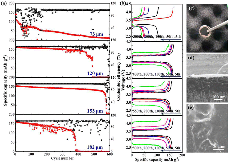
Inspired by the desirable cyclability performance realized at room temperature, we further explore the high-temperature performance (48 °C) of this battery system at 0.5C. As presented in Fig. 7(a) and (b), the long-term capacity retention is markedly enhanced. For the batteries with a membrane thickness of 120 and 153 μm, a much more prolonged lifespan is achieved. Especially for the latter, the battery can be cycled up to 560 cycles, maintaining 74.5% capacity retention with a stabilized CE of almost 100%. On the contrary, batteries with a membrane thickness of 73 and 182 μm suffer from rapid decay in capacity. The photograph in Fig. 7(c) illustrates that both LFP and Li electrodes are intimately embedded into the sticky PIL membrane, rendering an integrated electrode/electrolyte interface. No obvious dividing line can be found to distinguish the solid electrolyte from electrodes (Fig. 7(d)). After cycling, there is no clear variation observed on the membrane surface in Fig. 7(e), indicating its inertness to high-temperature processing. The outcome manifests that the polymer electrolyte is well-compatible with the electrodes. Table 1 and Table S3 (ESI†) compare the critical features and electrochemical performance of the PIL electrolyte with recently reported various electrolytes conceived for LMBs. The comparison not only shows the outstanding ionic conductivity of the PIL electrolyte, but also explicitly presents the remarkable thermal endurance, oxidative stability, and easy device integration. In consideration of these excellent traits, the PIL electrolyte is highlighted as a strong competitor for use in high-energy-density solid-state LMBs.
| Polymer electrolyte | Ionic conductivity/ × 10−4 S cm−1 | Operating temperature | Capacity retention | Test rate | Cycling performance based on Li/LiFePO4 batteries |
|---|---|---|---|---|---|
| EMIMTFSI/P(MMA-co-AMIMTFSI)25 | 1.9 at 25 °C | 25 °C | 65.5% | 0.2C | 76.3 mA h g−1 after 90 cycles |
| PEO networks crosslinked by imine and disulfide bonds27 | 6.97 at 25 °C | 25 °C | 88.4% | 0.1C | 128.5 mA h g−1 after 300 cycles |
| EMITFSI-poly(C1-4TFSI)-PDDATFSI34 | 10.6 at 25 °C | 25 °C | 97.7% | 0.1C | 147.1 mA h g−1 after 100 cycles |
| TEOS in PAN38 | 4.3 at 20 °C | 25 °C | 84.7% | 0.5C | 114.9 mA h g−1 after 400 cycles |
| XVIm-TFSI-PEGDME41 | >1.0 at 25 °C | 25 °C | 93.8% | 0.2C | 155.0 mA h g−1 after 150 cycles |
| FB-SPE (PEGMA-HFBMA)42 | 1.45 at 70 °C | 70 °C | 96% | 0.1C | 101.7 mA h g−1 after 60 cycles |
| Br-modified cellulose-Li salt-PEGA43 | 0.35 at 25 °C | 60 °C | 91.8% | 0.1C | 134.8 mA h g−1 after 110 cycles |
| PVDF-HFP-MPEGA-ETPTA-Pyr13TFSI-HMPP-LiTFSI52 | 11.9 at 25 °C | 55 °C | 98.3% | 0.5C | 148.5 mA h g−1 after 200 cycles |
| PSi-S-CN-DMPA53 | 0.045 at 25 °C | 60 °C | 75% | 0.1 mA cm−2 | 100.5 mA h g−1 after 150 cycles |
| PEO-Pyr1,(2O)7TFSI-LiTFSI54 | 6.6 at 25 °C | 40 °C | 99.3% | 1C | 151 mA h g−1 after 200 cycles |
| LATP-LiTFSI-Py13TFSI-PDADMATFSI55 | 1.03 at 40 °C | 50 °C | 95% | 0.1C | 166.25 mA h g−1 after 100 cycles |
| Poly(allyl diglycol carbonate)56 | 0.196 at 25 °C | 60 °C | 99.2% | 0.3C | 127.4 mA h g−1 after 110 cycles |
| EMIm-TFSI in cross-linking EPVIm-TFSI/PEI/PVDF-HFP network57 | 18 at 25 °C | 25 °C | 98% | 0.5C | 147.5 mA h g−1 after 200 cycles |
| Polymerized 1,3-dioxolane58 | 33.7 at 25 °C | 25 °C | 82.1% | 100 mA g−1 | 115 mA h g−1 after 200 cycles |
| ∼2.3C | |||||
| UPyMA-PEGMA-SSPSILi/PVDF-HFP59 | 0.278 at 30 °C | 25 °C | 93.6% | 0.1C | 105 mA h g−1 after 100 cycles |
| BC-g-PLiSTFSI-b-PEGM60 | 3.1 at 25 °C | 25 °C | ∼84% | 0.5C | 111 mA h g−1 after 300 cycles |
| Crosslinked PEGDE61 | 0.89 at 25 °C | 25 °C | 74.2% | 0.1C | 95 mA h g−1 after 100 cycles |
| SnF2 catalyzed P-DOL62 | 0.72 at 45 °C | 45 °C | 81.8% | 0.15C | 130 mA h g−1 after 350 cycles |
| Our work | 1.76 at 25 °C | 25 °C | 91.2% | 0.5C | 119.9 mA h g−1 after 206 cycles |
| 25 °C | 67.6% | 0.2C | 90.4 mA h g−1 after 392 cycles | ||
| 48 °C | 74.5% | 0.5C | 146.1 mA h g−1 after 560 cycles |
3. Conclusion
In conclusion, we introduced a new type of polymer electrolyte by grafting EMIM+ into the backbones of PMMA polymer, imparting chemical inertness against the Li anode, which is a characteristic of high Li+ transport and self-healing traits. Benefiting from the strong external H-bonding interactions, the obtained polymer electrolyte could spontaneously reconstruct dendrite-induced defects and fatigue crack growth at the Li/electrolyte interface, giving rise to uniform Li deposition. Owing to the resilient Li/electrolyte interface and dendrite-free Li plating, the Li|LFP batteries with self-healing polymer electrolyte display an optimal initial discharge capacity of 134.7 mA h g−1, rendering 91.2% capacity retention after 206 cycles at room temperature. When the operating temperature was raised to 48 °C, the battery could be cycled up to 560 cycles, maintaining 74.5% capacity retention with a stabilized CE of almost 100%. All the results illustrate the competitive advantages of the self-healing polymer for practical LMBs with highly improved safety and interfacial stability.Conflicts of interest
There are no conflicts to declare.Acknowledgements
The work is financially supported by the NSFC (21905141, 22203046, 91963119, 22179064, 62174087), China Postdoctoral Science Foundation (2020M681682), Priority Academic Program Development of Jiangsu Higher Education Institutions (YX03001), Synergetic Innovation Centre for Organic Electronics and Information Displays, and Jiangsu National Synergetic Innovation Centre for Advanced Materials (SICAM). The authors would like to thank Shiyanjia Lab (www.shiyanjia.com) for conducting the GPC tests.References
- D. C. Lin, Y. Y. Liu and Y. Cui, Nat. Nanotechnol., 2017, 12, 194–206 CrossRef CAS.
- Y. Cao, H. M. Lu, B. B. Xu, W. W. Yang and Q. S. Hong, Chem. Eng. J., 2019, 378, 122247 CrossRef CAS.
- Q. Wang, H. C. Wang, J. Y. Wu, M. Y. Zhou, W. Liu and H. H. Zhou, Nano Energy, 2021, 80, 105516 CrossRef CAS.
- Z. D. Hao, Q. Zhao, J. D. Tang, Q. Q. Zhang, J. B. Liu, Y. H. Jin and H. Wang, Mater. Horiz., 2021, 8, 12–32 RSC.
- R. Gond, W. V. Ekeren, R. Mogensen, A. J. Naylor and R. Younesi, Mater. Horiz., 2021, 8, 2913–2928 RSC.
- L. S. Su, A. Manthiram and A. Manthiram, Small Struct., 2022, 2200114 CrossRef CAS.
- P. Liu, H. Su, Y. Liu, Y. Zhong, C. X. Xian, X. L. Xia, Y. Q. Zhang, X. L. Wang, X. H. Xia and J. P. Tu, Small Struct., 2022, 3, 220010 Search PubMed.
- Y. Liu, Y. P. Zhai, Y. Y. Xia, W. Li and D. Y. Zhao, Small Struct., 2021, 2, 2000118 CrossRef CAS.
- H. Liu, X. B. Cheng, J. Q. Huang, H. Yuan, Y. Lu, C. Yan, G. L. Zhu, R. Xu, C. Z. Zhao, L. P. Hou, C. X. He, S. Kaskel and Q. Zhang, ACS Energy Lett., 2020, 5, 833–843 CrossRef CAS.
- M. Balaish, J. C. Gonzalez-Rosillo, K. J. Kim, Y. T. Zhu, Z. D. Hood and J. L. M. Rupp, Nat. Energy, 2021, 6, 227–239 CrossRef CAS.
- X. L. Xu, K. S. Hui, K. N. Hui, H. Wang and J. B. Liu, Mater. Horiz., 2020, 7, 1246–1278 RSC.
- A. Manthiram, X. W. Yu and S. F. Wang, Nat. Rev., 2017, 2, 16103 CAS.
- Y. Cao, H. M. Lu, Q. S. Hong, J. J. Bai, J. R. Wang and X. D. Li, J. Power Sources, 2017, 368(15), 78–87 CrossRef CAS.
- Y. Cao, H. M. Lu, Q. S. Hong, B. B. Xu, J. R. Wang, Y. Deng, W. W. Yang and W. Cai, Carbon, 2019, 144, 280–288 CrossRef CAS.
- W. R. Du, X. F. Du, M. B. Ma, S. Huang, X. F. Sun and L. L. Xiong, Adv. Funct. Mater., 2022, 32, 2110871 CrossRef CAS.
- N. Meng, F. Lian and G. L. Cui, Small, 2021, 17, 2005762 CrossRef CAS.
- W. W. Yang, H. M. Lu, Y. Cao and P. C. Jing, J. Power Sources, 2019, 441, 227173 CrossRef CAS.
- D. P. Wang, S. F. Zhao, R. Y. Yin, L. L. Li, Z. Lou and G. Z. Shen, npj Flexible Electron., 2021, 5, 13 CrossRef CAS.
- M. R. Crump, S. L. Bidinger, F. J. Pavinatto, A. T. Gong, R. M. Sweet and J. D. MacKenzie, npj Flexible Electron., 2021, 5, 7 CrossRef CAS.
- M. H. Kim, H. L. Park, M. H. Kim, J. Jang, J. H. Bae, I. M. Kang and S. H. Lee, npj Flexible Electron., 2021, 5, 34 CrossRef CAS.
- J. Hwang, K. Matsumoto, C. Y. Chen and R. Hagiwara, Energy Environ. Sci., 2021, 14, 5834–5863 RSC.
- C. Y. Fu, G. Homann, R. Grissa, D. Rentsch, W. G. Zhao, T. Gouveia, A. Falgayrat, R. Y. Lin, S. Fantini and C. Battaglia, Adv. Energy Mater., 2022, 12, 2200412 CrossRef CAS.
- J. Zhang, Z. Y. Chen, Y. Zhang, S. Y. Dong, Y. F. Chen and S. G. Zhang, Adv. Mater., 2021, 33, 2100962 CrossRef CAS.
- Z. H. Luo, W. J. Li, J. P. Yan and J. Sun, Adv. Funct. Mater., 2022, 32, 2203988 CrossRef CAS.
- C. X. Guo, Y. F. Cao, J. F. Li, H. P. Li, S. K. Arumugam, S. Oleksandr and F. Chen, Appl. Energy, 2022, 323, 119571 CrossRef CAS.
- Z. Li, J. L. Fu, S. Zheng, D. G. Li and X. Guo, Small, 2022, 18, 2200891 CrossRef CAS.
- Z. X. Huang, Z. H. Xie, Z. P. Zhang, T. Zhang, M. Z. Rong and M. Q. Zhang, J. Mater. Chem. A, 2022, 10, 18895–18906 RSC.
- X. Lin, X. Liu, S. Xu, Z. Liu, C. Zhao, R. Liu, P. Li, X. Feng and Y. Ma, New J. Chem., 2022, 46, 10379–10385 RSC.
- S. Z. Wang, J. W. Hu, X. F. Gui, S. D. Lin and Y. Y. Tu, J. Electrochem. Soc., 2021, 168, 020514 CrossRef CAS.
- S. F. Xiang, S. S. Chen, M. T. Yao, F. Zheng and Q. H. Lu, J. Mater. Chem. C, 2019, 7, 9625–9632 RSC.
- B. Yu, F. Zhou, C. W. Wang and W. M. Liu, Eur. Polym. J., 2007, 43, 2699–2707 CrossRef CAS.
- S. J. Ding, H. D. Tang, M. Radosz and Y. Q. Shen, Polym. Chem., 2004, 42, 5794–5801 CrossRef CAS.
- T. H. Zhou, Y. Zhao, J. W. Choi and A. Coskun, Angew. Chem., Int. Ed., 2021, 60, 22791–22796 CrossRef CAS PubMed.
- D. Zhou, R. L. Liu, J. Zhang, X. G. Qi, Y. B. He, B. H. Li, Q. H. Yang, Y. S. Hu and F. Y. Kang, Nano Energy, 2017, 33, 45–54 CrossRef CAS.
- S. Hess, M. Wohlfahrt-Mehrens and M. Wachtler, J. Electrochem. Soc., 2015, 162, A3084 CrossRef CAS.
- Q. Liu, D. Zhu, D. Shanmukaraj, P. Li, F. Y. Kang, B. H. Li, M. Armand and G. X. Wang, ACS Energy Lett., 2020, 5, 1456–1464 CrossRef CAS.
- K. Q. He, S. H. Cheng, J. Y. Hu, Y. Q. Zhang, H. W. Yang, Y. Y. Liu, W. C. Liao, D. Z. Chen, C. Z. Liao, X. Cheng, Z. G. Lu, J. He, J. N. Tang, R. K. Y. Li and C. Liu, Angew. Chem., Int. Ed., 2021, 60, 12116–12123 CrossRef CAS.
- M. Yao, H. T. Zhang, C. X. Xing, Q. G. Li, Y. J. Tang, F. J. Zhang, K. Yang and S. J. Zhang, Energy Storage Mater., 2021, 41, 51–60 CrossRef.
- K. Pożyczka, M. Marzantowicz, J. R. Dygas and F. Krok, Electrochim. Acta, 2017, 227, 127–135 CrossRef.
- H. Kim, W. Choi, J. Yoon, J. H. Um, W. Lee, J. Kim, J. Cabana and W. S. Yoon, Chem. Rev., 2020, 120, 6934–6976 CrossRef CAS PubMed.
- Y. C. Tseng, S. H. Hsiang, C. H. Tsao, H. Teng, S. S. Hou and J. S. Jan, J. Mater. Chem. A, 2021, 9, 5796–5806 RSC.
- M. Y. Jia, P. Wen, Z. T. Wang, Y. C. Zhao, Y. M. Liu, J. Lin, M. Chen and X. R. Lin, Adv. Funct. Mater., 2021, 2101736 CrossRef CAS.
- Y. Zhang, L. P. Yu, J. R. Wang, S. Q. Li, H. H. Gan and Z. G. Xue, J. Membr. Sci., 2021, 626, 119210 CrossRef CAS.
- J. Tan, J. Matz, P. Dong, J. F. Shen and M. X. Ye, Adv. Energy Mater., 2021, 11, 2100046 CrossRef CAS.
- P. Jaumaux, Q. Liu, D. Zhang, X. F. Xu, T. Y. Wang, Y. Z. Wang, F. Y. Kang, B. H. Li and G. X. Wang, Angew. Chem., Int. Ed., 2020, 59, 9134–9143 CrossRef CAS.
- C. Y. Chang, Y. Yao, R. R. Li, Z. H. Guo, L. W. Li, C. X. Pan, W. G. Hu and X. Pu, Nano Energy, 2022, 93, 106871 CrossRef CAS.
- W. W. Yang, H. M. Lu, Y. Cao, P. C. Jing, X. Q. Hu and H. Yu, Ionics, 2020, 26, 3405–3413 CrossRef CAS.
- W. W. Yang, H. M. Lu, Y. Cao, B. B. Xu, Y. Deng and W. Cai, ACS Sustainable Chem. Eng., 2019, 7, 4861–4867 CrossRef CAS.
- J. X. Liu, C. Zhang, S. Q. Yuan, W. W. Yang, Y. Cao, J. Y. Deng, B. B. Xu and H. M. Lu, Chem. Eng. J., 2022, 428, 131326 CrossRef CAS.
- Z. Zhang, Y. Huang, H. Gao, C. Li, J. X. Hang and P. B. Liu, J. Energy Chem., 2021, 60, 259–271 CrossRef CAS.
- J. Y. Wu, L. X. Yuan, W. X. Zhang, Z. Li, X. L. Xie and Y. H. Huang, Energy Environ. Sci., 2021, 14, 12–36 RSC.
- Z. Chen, Y. Yang, Q. T. Su, S. D. Huang, D. Song, R. Ma, C. Z. Zhu, G. H. Lv and C. H. Li, ACS Appl. Mater. Interfaces, 2021, 13, 41946–41955 CrossRef CAS.
- C. Y. Fu, M. Iacob, Y. Sheima, C. Battaglia, L. Duchêne, L. Seidl, D. M. Opris and A. Remhof, J. Mater. Chem. A, 2021, 9, 11794–11801 RSC.
- J. Atik, D. Diddens, J. H. Thienenkamp, G. Brunklaus, M. Winter and E. Paillard, Angew. Chem., Int. Ed., 2021, 60, 11919–11927 CrossRef CAS PubMed.
- X. L. Song, H. T. Zhang, D. F. Jiang, L. P. Yang, J. H. Zhang, M. Yao, X. Y. Ji, G. Y. Wang and S. J. Zhang, Electrochim. Acta, 2021, 368, 137581 CrossRef CAS.
- Y. B. Chen, G. P. Chen, C. Q. Niu, W. Y. Shang, R. T. Yu, C. X. Fang, P. Ouyang and J. Du, Polymer, 2021, 223, 123695 CrossRef CAS.
- L. Liang, X. H. Chen, W. F. Yuan, H. Chen, H. Y. Liao and Y. Q. Zhang, ACS Appl. Mater. Interfaces, 2021, 13, 25410–25420 CrossRef CAS PubMed.
- S. S. Wang, L. Zhou, M. K. Tufail, L. Yang, P. F. Zhai, R. J. Chen and W. Yang, Chem. Eng. J., 2021, 415, 128846 CrossRef CAS.
- H. H. Gan, S. Q. Li, Y. Zhang, L. P. Yu, J. R. Wang and Z. G. Xue, Langmuir, 2021, 37, 8270–8280 CrossRef CAS PubMed.
- M. H. Zhou, R. L. Liu, D. Y. Jia, Y. Cui, Q. T. Liu, S. H. Liu and D. C. Wu, Adv. Mater., 2021, 33, 2100943 CrossRef CAS PubMed.
- Y. Y. Cui, X. M. Liang, J. C. Chai, Z. L. Cui, Q. L. Wang, W. S. He, X. C. Liu, Z. H. Liu, G. L. Cui and J. W. Feng, Adv. Sci., 2017, 4, 1700174 CrossRef.
- W. Li, J. Gao, H. Y. Tian, X. L. Li, S. He, J. P. Li, W. L. Wang, L. Li, H. Li, J. S. Qiu and W. D. Zhou, Angew. Chem., Int. Ed., 2022, 134, e202114805 Search PubMed.
Footnote |
| † Electronic supplementary information (ESI) available. See DOI: https://doi.org/10.1039/d2mh01289h |
| This journal is © The Royal Society of Chemistry 2023 |

