 Open Access Article
Creative Commons Attribution 3.0 Unported Licence
Photon pairs bi-directionally emitted from a resonant metasurface†
Changjin
Son
 *ab,
Vitaliy
Sultanov
ab,
Tomás
Santiago-Cruz
 ab,
Aravind P.
Anthur
c,
Haizhong
Zhang
c,
Ramon
Paniagua-Dominguez
 c,
Leonid
Krivitsky
c,
Arseniy I.
Kuznetsov
c and
Maria V.
Chekhova
c,
Leonid
Krivitsky
c,
Arseniy I.
Kuznetsov
c and
Maria V.
Chekhova
 ab
ab
aMax Planck Institute for the Science of Light, 91058 Erlangen, Germany. E-mail: changjin.son@mpl.mpg.de
bFriedrich-Alexander Universität Erlangen-Nürnberg, 91058 Erlangen, Germany
cA*STAR (Agency for Science, Technology and Research) Research Entities, Institute of Materials Research and Engineering, Singapore 138634, Singapore. E-mail: aravind_padath_anthur@imre.a-star.edu.sg
First published on 3rd January 2023
Abstract
Metasurfaces are artificially structured surfaces able to control the properties of light at subwavelength scales. While, initially, they have been proposed as means to control classical optical fields, they are now emerging as nanoscale sources of quantum light, in particular of entangled photons with versatile properties. Geometric resonances in metasurfaces have been recently used to engineer the frequency spectrum of entangled photons, but the emission directivity was so far less studied. Here, we generate photon pairs via spontaneous parametric down conversion from a metasurface supporting a quasi-bound state in the continuum (BIC) leading to remarkable emission directivities. The pair generation rate is enhanced 67 times compared to the case of an unpatterned film of the same thickness and material. At the wavelength of the quasi-BIC resonance, photons are mostly emitted backwards, while their partners, spectrally detuned by only 8 nm, are emitted forwards. This behavior demonstrates fine spectral splitting of entangled photons and their bi-directional emission, never before observed in nanoscale sources. We expect this work to be a starting point for the efficient demultiplexing of photons in nanoscale quantum optics.
Nanoscale sources of light, such as nanoantennas, monoatomic or few-atomic layers, and metasurfaces, are successfully competing with their bulk counterparts as nonlinear frequency converters.1,2 Their advantages are small footprint, versatile spectral properties, access to high nonlinearities and large field enhancements, possible tunability, and multifunctional operation. In recent years, they are also considered as promising elements for quantum photonics.3–5 Used at first just for the transformation and shaping of quantum light3 and for the generation of single photons,4,6 various nanoscale platforms are now producing entangled photons, through spontaneous four-wave mixing7 and spontaneous parametric down-conversion (SPDC).8–14 In particular, resonances in metasurfaces enable the enhancement of SPDC efficiency and shaping the spectrum of the emitted photon pairs.10,14 At the same time, an important degree of freedom for photon pairs – namely, the direction of emission – remains almost unexplored.15 So far, photon pairs have been generated from nanoscale sources either (nearly) collinearly with the pumping radiation,9,11–14 or in the backward direction.8,10 Meanwhile, careful engineering of such sources could offer a possibility of bi-directional emission of photons. Such a possibility, in particular, would provide an easy way of splitting the photons of a pair. Although counter-propagating photon pairs have been generated in waveguides,16–18 no such results have been reported for nanoscale platforms so far.
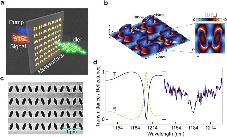
In this work, we demonstrate bi-directional emission of photon pairs through SPDC in a gallium phosphide (GaP) metasurface supporting a quasi-BIC resonance. In SPDC, a higher-energy photon of the pump radiation spontaneously decays, due to the second-order nonlinear susceptibility χ(2), into a pair of lower-energy photons, called signal and idler, as depicted in Fig. 1a for the case of oppositely emitted photon pairs. While the momentum conservation in an ultrathin source like a metasurface is relaxed,19 the energy conservation requires the relation between the wavelengths of the signal (s), idler (i), and pump (p) photons: λi−1 + λs−1 = λp−1.
All-dielectric metasurfaces supporting quasi-BIC resonances are attractive platforms for SPDC due to their relatively high damage threshold, allowing pump powers up to few tens of mW, resonances with high quality (Q) factors, leading to the enhancement of pair emission if one of the photons is at a resonance,10,14 and the possibility to use materials with high χ(2).
We use a GaP metasurface (Fig. 1b and c) where each unit cell is formed by two elliptical nano-cylinders with the major axis, minor axis, and height equal to 450 nm, 200 nm, and 150 nm, respectively. The centre-to-centre distance between the ellipses is 340 nm and the period of the unit cells is 700 nm. The total footprint of the metasurface is 100 μm × 100 μm.
Such a metasurface supports high-Q eigenmodes at the Γ point (i.e. when all unit cells have zero phase delay) that emerge from the destructive interference between the in-plane electric dipoles excited on each elliptic cylinder. If the cylinders are parallel and the dipoles anti-parallel, the resulting charge-current configuration is purely non-radiative in the direction perpendicular to the surface, corresponding to an out-of-plane magnetic dipole and an in-plane electric quadrupole. The resulting mode is a bound state in the continuum (BIC), which, for an infinite array, has an infinitely high Q factor, as it is completely decoupled from the far field.20 A controlled coupling can be achieved by breaking the symmetry of the unit cell, e.g. by tilting the ellipses with respect to each other.21 The resulting projection of the electric dipole moment on the metasurface plane (along the x axis in Fig. 1b) enables a quasi-BIC mode that can now weakly couple to the far field. (See ESI Fig. S1† schematically depicting how the quasi-BIC is formed.) One can control the Q factor of the resonance by varying the tilt angle: a larger angle enables a better coupling to the far field but reduces the Q factor. In this work, we use a metasurface with 20° tilt angle, which, according to simulations (Fig. 1d, left), has a resonance at 1208 nm, seen as a dip in the transmission spectrum and a peak in the reflection spectrum, with the width of 10 nm. Our measurement (Fig. 1d, right; see also the ESI†) shows the resonance at 1184 nm, somewhat blue-shifted compared to the simulated spectrum, which could be caused by imperfections in the fabrication or oxidization of the sample. This resonance, with Q ≈ 100, proved very efficient for the second harmonic generation (SHG).22
Here, we use the metasurface in the ‘reversed’ way: while in SHG, two photons merge to become a single higher-energy photon, in SPDC a single pump photon splits in two. The difference is that in SPDC, the signal and idler photons do not have to be at the same wavelength; in fact, in our experiment only one of them (further called the signal) is emitted at the resonance wavelength. The quasi-BIC resonance enhances the quantum vacuum field at the signal wavelength, which, in turn, should increase the rate of SPDC.14 The wavelength of the idler photon is defined by the energy conservation and can be shifted from the resonance. In this work, however, our main study focuses on the directionality of the signal and idler photons emission.
Despite the relaxed phase matching, SPDC in sources thicker than few tens of nm has a certain directivity. Indeed, the forward emission of both photons is still preferable to their backward emission and even to the bi-directional emission because in the two latter cases, the wavevector mismatch is still much larger than the inverse thickness of the source. In metasurfaces, however, recent SPDC experiments showed very different behavior. In particular, in some metasurfaces, signal and idler photons were both emitted mainly backwards and only in the vicinity of the resonance.10,15 In other metasurfaces, both photons of a pair were emitted forwards, with only one of them being at the resonant wavelength.14 This can be explained by resonances of the metasurfaces, which affect the emission directivity. Here, we demonstrate bi-directional emission from a metasurface with quasi-BIC resonances that support only normally coupled resonant modes at 1184 nm.
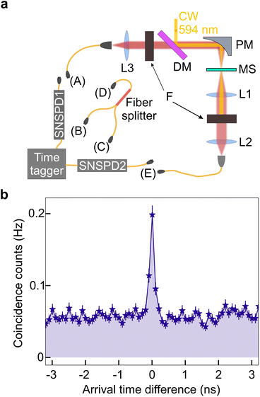
In experiment (Fig. 2a), we send continuous-wave (CW) pump at 594 nm into the setup through a dichroic mirror (DM) and focus it into the metasurface (MS) by a parabolic mirror (PM) with the focal distance 50 mm. The pump is polarized along the x direction (Fig. 1a), corresponding to the net electric dipole moment of the metasurface unit cell (see the ESI†). The spot size on the metasurface is 100 μm in diameter. For collecting SPDC photons, the setup has transmission and reflection arms. In the transmission arm, we collimate the photon pairs with lens L1 (focal length 50 mm) and filter out the pump by a bandpass filter (central wavelength 1200 nm, bandwidth 50 nm). In the reflection arm, the emitted photons are collimated by the parabolic mirror and transmitted through the dichroic mirror. At both outputs, photons are coupled into a single-mode fiber (SMF) by lenses L2, L3, with focal lengths 20 mm, and registered by superconducting-nanowire single-photon detectors SNSPD1,2.
To register photon pairs, we use the Hanbury Brown – Twiss setup, splitting the photon flux between two SNSPDs and registering the simultaneous arrivals of photons at both detectors. We investigate three possible photon pair detection geometries: with both photons of a pair emitted forward (forward–forward), with both photons emitted backward (backward–backward), and ‘bidirectional’ pairs, where one photon is emitted forward and the other one, backward (forward–backward). The measurement geometry is changed by choosing a certain connection between the setup outputs, SNSPDs, and a fibre beam splitter. In particular, for backward–backward (forward–forward) detection, we connect the SMF output A (E) with the input port D of the fibre beam splitter, whose two output ports B, C, in their turn, are connected to SNSPD1,2. For the forward–backward geometry, we connect the A and E output ports with SNSPD1 and SNSPD2, respectively.
The output pulses of the detectors are sent to a time tagger, which builds the distribution of their arrival time difference. Fig. 2b shows this histogram for the forward–backward geometry, with the pump power 70 mW. The narrow peak at the center indicates the simultaneous arrival of both photons at the detectors (coincidence counts). Its width, approximately 200 ps, is determined by the time jitter of the detectors. The background is caused by the accidental overlap of photons, mostly due to the photoluminescence of the sample. Its level is relatively high because the energy of the pump photons is close to the bandgap of GaP. Still, the peak-to-background ratio, also called coincidences-to-accidentals ratio (CAR), exceeds 2 and this is an indication of pair emission.19 The rate of pair generation is obtained by integrating all events in the peak above the background and amounts to 0.24 ± 0.02 counts per s. For forward–forward and backward–backward geometries, we also observe coincidences with CAR exceeding 2 (see the ESI†), but the rates of pair generation are different, see Table 1, second column.
| Direction of photons | Coincidence rate [counts per s] | FWHM [nm] |
|---|---|---|
| Forward–forward | 0.04 ± 0.01 | 6 |
| Forward–backward | 0.24 ± 0.02 | 14 |
| Backward–backward | 0.15 ± 0.02 | 5 |
We see that most (56%) of the photon pairs are registered bidirectionally, one photon in the forward and the other one in the backward direction. Among the registered pairs, only 9% are ‘forward–forward’ ones, which corresponds to the most common geometry of SPDC observation. Partly, the rates of ‘unidirectionally’ emitted pairs are low because such pairs have to be split by a beamsplitter, in which half of them are sent into a single output port and not counted as a pair. But largely, this is because the metasurface tends to emit the signal photon (at resonance) backwards, while the idler photon (off the resonant peak, at its shoulder) is emitted forwards or backwards, with close to equal probabilities. It should be also noted that in an unstructured non-resonant layer, both signal and idler photons are mostly emitted forwards (see the ESI†).
Further, we study the spectra of the photons emitted in all three geometries. Because of the low SPDC rate, masked by much stronger photoluminescence, we obtain the spectra using the method of two-photon fibre spectroscopy, where only coincidence counts are registered. In this method, a fibre is inserted into the path of one or both photons, and the time delay τ between the photons of a pair, caused by the group velocity dispersion in the fibre, is mapped to their wavelength separation Δλ.23 For pairs emitted not far from the degenerate wavelength λdeg, after a fibre of length L inserted into the path of one photon, the time delay is
| τ = D(λdeg)·L·Δλ, | (1) |
With this method, we measure the spectra for three different geometries. For the backward–backward (forward–forward) cases, we insert 3 km of SMF-28 fibre between the A (E) outputs of the setup and the D input of the fibre beamsplitter. Because both signal and idler photons travel through the fibre, the right-hand side of eqn (1) should contain 2L instead of L. With D(λdeg) ≈ −13.79 ps nm−1 km−1, the spectral resolution is 2.8 nm.
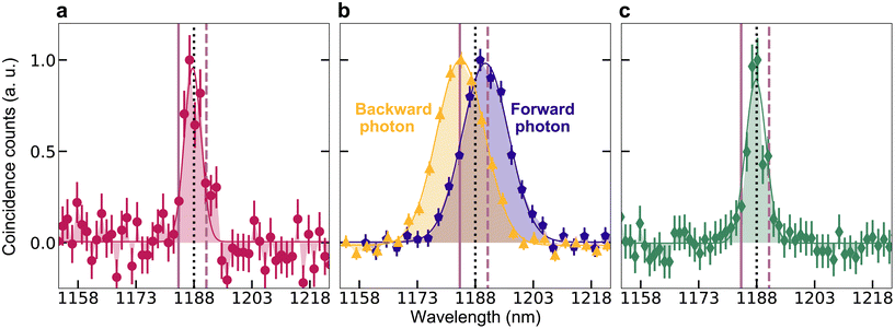
For the forward–backward case, we insert 3 km of SMF-28 fibre between SNSPD 2 and the A or E output port. The spectral resolution is in both cases 4.4 nm. Fig. 3 shows the normalized spectra of photon pairs measured for all three cases. Red solid vertical lines in each graph indicate the resonance wavelength λs = 1184 nm, at which signal photons are emitted, and dashed vertical lines, the idler wavelength λi = 1192 nm, related to it through the energy conservation condition. The degenerate wavelength 1188 nm is marked by a black dotted line. Solid lines are Gaussian fitting curves for each measurement.
In both forward–forward (panel a) and backward–backward (panel c) geometries, we observe a relatively narrow peak centered at the degenerate wavelength. In the bidirectional geometry (panel b), the spectra are different for the photons emitted forward and backward, shown by blue pentagons and orange triangles, respectively. As expected, the signal photon, at the resonance wavelength, is emitted in the direction opposite to the pump, while its idler ‘partner’ is emitted codirectionally with the pump. We also notice that the widths of the spectra are different: while the bidirectional emission has full width at half maximum (FWHM) 14 nm, close to the width of the resonance, the spectra of pairs emitted fully forward or fully backward are twice as narrow (Table 1, third column). This behavior resembles the one observed for a Mie-resonance metasurface in reflection geometry,10 where the spectrum of backward generated pairs was also somewhat narrower than the resonance. Apparently, this can happen because photons within the resonance band (signal photons) are mostly emitted backwards (orange curve in Fig. 3b), while their idler partners within the spectral band shifted symmetrically with respect to the degenerate wavelength (blue curve in Fig. 3b) are mainly emitted forward, contributing only to forward–backward counts. Thus, the unidirectional pairs, emitting either both forward or both backward, can only be within the narrow spectral minimum around the degenerate wavelength in Fig. 3b, where fewer forward–backward pairs are generated.
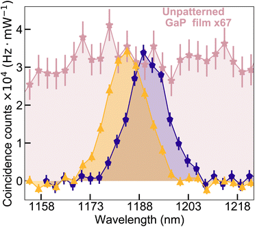
Finally, Fig. 4 demonstrates the enhancement provided by the quasi-BIC resonance. To evaluate it, we measure the spectrum of photon pairs emitted by an unpatterned GaP film of thickness 400 nm‡ in the forward–backward geometry. The corresponding spectrum is shown by pink colour, after normalization by a factor of 7, due to the larger film thickness, which enters quadratically, and to the pump power, which was only 20 mW in this case. After overlapping this spectrum with the spectral distribution of pairs bidirectionally emitted from the metasurface, we see that the latter provides a 67-times enhancement in coincidence rate compared to an unpatterned GaP film of the same thickness. This enhancement is only observed within a narrow spectral range, while the unpatterned film, as in earlier experiments,9,10 generates a very broad SPDC spectrum. For the most efficient case, forward–forward emission, the unpatterned GaP film of thickness 400 nm showed a count rate of ∼0.18 Hz with 65 mW pump over the effective bandwidth 26.3 nm (see the ESI†).
The pair generation rate increases due to the resonance of the metasurface. The vacuum field at the resonance frequency is enhanced and it results in the enhanced pair generation when the signal photon is emitted at the resonance frequency. The enhancement is proportional to the Q factor since it describes how much field is confined in the material.
We also compare the coincidence rate to ones obtained in previous works for lithium niobate (LiNbO3)10 and gallium arsenide (GaAs)14 metasurfaces, and a LiNbO3 layer where SPDC is enhanced nonlocally with a metasurface13 in Table 2. The count rates per unit pump power are low compared to bulk sources because of the small thicknesses of the metasurfaces; however, they are still substantial due to the resonant enhancement. Note that the coincidence rate should scale quadratically with the thickness, which explains the low rate obtained for our metasurface, the thinnest one in the list. The table also shows the enhancement of the coincidence rate compared to that of unpatterned films of the same thickness. This enhancement scales with the Q factors of the resonances, but it also depends on the electric field direction with respect to the nonlinear tensor structure.
In conclusion, we have generated photon pairs via SPDC in a GaP metasurface with a quasi-BIC resonance. The metasurface has a peak of reflectivity (and a dip of transmissivity) at the resonance wavelength. As a result, photon pairs are preferably generated with the signal photon at the resonance wavelength and the corresponding idler photon at the wavelength satisfying the energy conservation. The spectral rate of photon pair generation is in this case enhanced 67 times compared to SPDC in an unpatterned film of the same thickness. The study of the directionality of pair emission showed that among the photon pairs, only 9% are registered in the common ‘forward’ geometry and 35%, in the ‘backward’ geometry. Most (56%) of photon pairs are registered bidirectionally. The photon at the resonance wavelength is emitted backwards and its pair photon is emitted forwards.
Such bidirectional emission has been never observed before in nanoscale sources. It demonstrates an example of multifunctional operation: the metasurface not only generates a photon pair, but splits the two photons, whose wavelengths differ by only 8 nm. These results will help in the design of metasurfaces for the generation of quantum states of light. In particular, the bidirectional emission of correlated photons enables heralded preparation of single photons. Moreover, the use of both (forward–backward) directions of emission will fuel the development of more complicated architectures of nanoscale sources of quantum light.
Author contributions
T. S.-C., L. K. and M. V. C. designed the study; R. P.-D. designed the metasurface and simulated the linear response; H. Zh. fabricated the metasurface; A. I. K. coordinated the metasurface design and fabrication process; A. P. A. and Ch. S. characterized the linear response; Ch. S., V. S. and T. S.-C. measured the nonlinear response (SHG) and performed quantum optical (SPDC) experiments; Ch. S., V. S. and T. S.-C. analyzed the data; Ch. S., T. S.-C. and M. V. C. wrote the manuscript with inputs from all authors.Conflicts of interest
There are no conflicts to declare.Acknowledgements
V. S., T. S.-C., and M. V. C. are part of the Max Planck School of Photonics supported by BMBF, Max Planck Society, and Fraunhofer Society. V. S. and M. V. C. acknowledge support by the Deutsche Forschungsgemeinschaft, Project ID 429529648, TRR 306 QuCoLiMa (“Quantum Cooperativity of Light and Matter”). A. P. A. acknowledges funding support from A*STAR, Singapore strategic program number C210917001. R. P.-D. and A. I. K. acknowledge support from Singapore RIE2020 AME Programmatic Funding (A18A7b0058), and National Research Foundation of Singapore under Grant no. NRF-NRFI2017-01. Open Access funding provided by the Max Planck Society.References
- A. Krasnok, M. Tymchenko and A. Alù, Mater. Today, 2018, 21, 8–21 CrossRef CAS.
- A. Autere, H. Jussila, Y. Dai, Y. Wang, H. Lipsanen and Z. Sun, Adv. Mater., 2018, 30, 1705963 CrossRef PubMed.
- A. S. Solntsev, G. S. Agarwal and Y. S. Kivshar, Nat. Photonics, 2021, 15, 327–336 CrossRef CAS.
- C. Chakraborty, N. Vamivakas and D. Englund, Nanophotonics, 2019, 8, 2017–2032 Search PubMed.
- K. Wang, M. Chekhova and Y. Kivshar, Phys. Today, 2022, 75, 38–44 CrossRef.
- M. Toth and I. Aharonovich, Annu. Rev. Phys. Chem., 2019, 70, 123–142 CrossRef CAS PubMed.
- K. F. Lee, Y. Tian, H. Yang, K. Mustonen, A. Martinez, Q. Dai, E. I. Kauppinen, J. Malowicki, P. Kumar and Z. Sun, Adv. Mater., 2017, 29, 1605978 CrossRef PubMed.
- G. Marino, A. S. Solntsev, L. Xu, V. F. Gili, L. Carletti, A. N. Poddubny, M. Rahmani, D. A. Smirnova, H. Chen, A. Lemaître, G. Zhang, A. V. Zayats, C. D. Angelis, G. Leo, A. A. Sukhorukov and D. N. Neshev, Optica, 2019, 6, 1416–1422 CrossRef CAS.
- T. Santiago-Cruz, V. Sultanov, H. Zhang, L. A. Krivitsky and M. V. Chekhova, Opt. Lett., 2021, 46, 653–656 CrossRef PubMed.
- T. Santiago-Cruz, A. Fedotova, V. Sultanov, M. A. Weissflog, D. Arslan, M. Younesi, T. Pertsch, I. Staude, F. Setzpfandt and M. Chekhova, Nano Lett., 2021, 21, 4423–4429 CrossRef CAS PubMed.
- V. Sultanov, T. Santiago-Cruz and M. V. Chekhova, Opt. Lett., 2022, 47, 3872–3875 CrossRef CAS PubMed.
- Q. Guo, X.-Z. Qi, M. Gao, S. Hu, L. Zhang, W. Zhou, W. Zang, X. Zhao, J. Wang, B. Yan, M. Xu, Y.-K. Wu, G. Eda, Z. Xiao, H. Gou, Y. P. Feng, G.-C. Guo, W. Zhou, X.-F. Ren, C.-W. Qiu, S. J. Pennycook and A. T. S. Wee, Ultrathin quantum light source enabled by a nonlinear van der Waals crystal with vanishing interlayer-electronic-coupling, 2022, DOI:10.1038/s41586-022-05393-7.
- J. Zhang, J. Ma, M. Parry, M. Cai, R. Camacho-Morales, L. Xu, D. N. Neshev and A. A. Sukhorukov, Sci. Adv., 2022, 8, eabq4240 CrossRef CAS PubMed.
- T. Santiago-Cruz, S. D. Gennaro, O. Mitrofanov, S. Addamane, J. Reno, I. Brener and M. V. Chekhova, Science, 2022, 377, 991–995 CrossRef CAS PubMed.
- T. Santiago-Cruz, A. Fedotova, V. Sultanov, M. Weissflog, M. Younesi, I. Staude, T. Pertsch, F. Setzpfandt and M. V. Chekhova, Conference on Lasers and Electro-Optics, 2021, p. FTh1O.5.
- I. Z. Latypov, A. A. Shukhin, D. O. Akat'ev, A. V. Shkalikov and A. A. Kalachev, Quantum Electron., 2017, 47, 827 CrossRef CAS.
- K.-H. Luo, V. Ansari, M. Massaro, M. Santandrea, C. Eigner, R. Ricken, H. Herrmann and C. Silberhorn, Opt. Express, 2020, 28, 3215–3225 CrossRef PubMed.
- Y.-C. Liu, D.-J. Guo, K.-Q. Ren, R. Yang, M. Shang, W. Zhou, X. Li, C.-W. Sun, P. Xu and Z. Xie, et al. , Sci. Rep., 2021, 11, 1–6 CrossRef PubMed.
- C. Okoth, A. Cavanna, T. Santiago-Cruz and M. Chekhova, Phys. Rev. Lett., 2019, 123, 263602 CrossRef CAS PubMed.
- Z. Dong, Z. Mahfoud, R. Paniagua-Domínguez, H. Wang, A. I. Fernández-Domínguez, S. Gorelik, S. T. Ha, F. Tjiptoharsono, A. I. Kuznetsov, M. Bosman and J. K. W. Yang, Light: Sci. Appl., 2022, 11, 20 CrossRef CAS PubMed.
- K. Koshelev, S. Lepeshov, M. Liu, A. Bogdanov and Y. Kivshar, Phys. Rev. Lett., 2018, 121, 193903 CrossRef PubMed.
- A. P. Anthur, H. Zhang, R. Paniagua-Dominguez, D. A. Kalashnikov, S. T. Ha, T. W. Maß, A. I. Kuznetsov and L. Krivitsky, Nano Lett., 2020, 20, 8745–8751 CrossRef CAS PubMed.
- A. Valencia, M. V. Chekhova, A. Trifonov and Y. Shih, Phys. Rev. Lett., 2002, 88, 183601 CrossRef PubMed.
Footnotes |
| † Electronic supplementary information (ESI) available. See DOI: https://doi.org/10.1039/d2nr05499j |
| ‡ For a film of the same thickness as the metasurface (150 nm), the rate of pairs was so low that no spectra could be measured. |
| This journal is © The Royal Society of Chemistry 2023 |


![[thin space (1/6-em)]](https://www.rsc.org/images/entities/char_2009.gif)