Finite-field Cholesky decomposed coupled-cluster techniques (ff-CD-CC): theory and application to pressure broadening of Mg by a He atmosphere and a strong magnetic field†
Received
6th August 2024
, Accepted 29th October 2024
First published on 14th November 2024
Abstract
For the interpretation of spectra of magnetic stellar objects such as magnetic white dwarfs (WDs), highly accurate quantum chemical predictions for atoms and molecules in finite magnetic field are required. Especially the accurate description of electronically excited states and their properties requires established methods such as those from coupled-cluster (CC) theory. However, respective calculations are computationally challenging even for medium-sized systems. Cholesky decomposition (CD) techniques may be used to alleviate memory bottlenecks. In finite magnetic field computations, the latter are increased due to the reduction of permutational symmetry within the electron-repulsion-integrals (ERIs) as well as the need for complex-valued data types. CD enables a memory-efficient, approximate description of the ERIs with rigorous error control and thus the treatment of larger systems at the CC level becomes feasible. In order to treat molecules in a finite magnetic field, we present in this work the working equations of the left and right-hand side equations for finite field (ff)-EOM-CD-CCSD for various EOM flavours as well as for the approximate ff-EOM-CD-CC2 method. The methods are applied to the study of the modification of the spectral lines of a magnesium transition by a helium atmosphere that can be found on magnetic WD stars.
1 Introduction
In the last decades, there has been a growing interest among astrophysicists in the study of (magnetic) white dwarfs (WDs) as part of the exploration of stellar evolution.1–6 Besides neutron stars and black holes, WDs represent the by far most common endpoint in the life cycle of stars, i.e., 95% of all stars become WDs. Of those approximately 25% exhibit magnetic properties, with magnetic field strengths reaching up to 0.4 B0 (1 B0 = 235![[thin space (1/6-em)]](https://www.rsc.org/images/entities/char_2009.gif) 052 T), where electronic and magnetic forces are at the same order of magnitude. In order to assign spectra from strongly magnetized WDs, predictions for transition wavelengths and intensities are required. Two main considerations have to be taken into account: first, the magnetic field has to be accounted for in the Hamiltonian in an explicit manner. It cannot be treated perturbatively as done in the weak-field limit for e.g. nuclear magnetic resonance (NMR), electron paramagnetic resonance (EPR) or magnetic circular dichroism (MCD) spectroscopy.7 Second, as electronic structure, bonding mechanisms, excitation energies and properties change significantly under the influence of such strong fields and no laboratory experiments are available, accurate computational predictions are crucial.
052 T), where electronic and magnetic forces are at the same order of magnitude. In order to assign spectra from strongly magnetized WDs, predictions for transition wavelengths and intensities are required. Two main considerations have to be taken into account: first, the magnetic field has to be accounted for in the Hamiltonian in an explicit manner. It cannot be treated perturbatively as done in the weak-field limit for e.g. nuclear magnetic resonance (NMR), electron paramagnetic resonance (EPR) or magnetic circular dichroism (MCD) spectroscopy.7 Second, as electronic structure, bonding mechanisms, excitation energies and properties change significantly under the influence of such strong fields and no laboratory experiments are available, accurate computational predictions are crucial.
Coupled-cluster (CC) methods8,9 allow for a precise electron-correlation treatment. However, respective CC calculations are highly demanding due to the steep scaling and memory bottlenecks.
In the absence of external magnetic fields, significant efforts have been made to tackle these issues and to improve the computational cost for standard CC methods. For example, Pulay and Sæbø10,11 introduced an approach which exploits the local nature of the short-range dynamic electron correlation that ultimately leads to sparse tensors, i.e., local correlation approaches. This ansatz uses orbital localization12–15 for the occupied space and only a subset of excitations to the virtual space within spatial vicinity is treated. Using the projected atomic orbital (PAO)16–18 representations for the virtual space efficient local CC implementations haven been realized by Werner and co-workers at the CC and equation-of-motion (EOM)-CC levels (CCSD,19–21 CCSD(T),22 and CC223), respectively. In addition, Neese et al.24 revived the use of the pair natural orbital (PNO)25–27 representation for the virtual space which led to the highly successful domain based (D)LPNO-CCSD28–30 scheme. An extension of this ansatz to excited states has been described by Dutta et al.31–33
Other approaches to remove the computational bottleneck are fragmentation-based schemes such as fragment molecular orbital (FMO)34–36 and molecular fractionation with conjugate caps (MFCC).37 Here, the whole system is divided into fragments and treated via a many-body expansion. The fragmentation methods are mainly used for the description of large clusters of weakly interacting monomers or the description of large biochemical molecules like peptides. These are molecular systems which can often also be addressed by the related multilevel embedding approaches, like QM/MM38,39 or QM/QM40 which allow for the accurate treatment of a desired subsystem while still describing the polarization and dynamics of the surrounding medium.
Instead of exploiting the sparsity of tensors via spatial locality of orbital subspaces or molecular fragments another ansatz is to use a rank-reduced approximation of the electron-repulsion integrals (ERIs). This ansatz is applied in density fitting (DF) also termed resolution-of-identity approximation (RI)41–50 or Cholesky decomposition (CD)51–56 approaches. Using either approach, the ERIs can represented by the product of rank three tensors. The RI approach uses a pre-optimised57–62 or automatically generated auxiliary basis63–67 in order to approximate the product density in the ERIs, whereas for the CD approach a CD of the ERIs is performed. Defining the Cholesky basis (CB) as collection of product densities corresponding to the pivots of the selected Cholesky vectors (CV), the latter two approaches become equivalent if the Cholesky basis is chosen as the auxiliary basis for RI.68,69 Since the reintroduction of CD by Koch, Sánchez de Merás and Pedersen52 in 2003, many methods exploiting the CD representation of the ERIs have been developed.53–56,70–80 The developments in CC theory include CD-(EOM)-CCSD,81–85 approximate CD-CC2 linear response86 as well as analytic gradients.82,87 While RI and CD achieve memory savings due to the rank reduction of the ERI tensor, the computational savings are mostly due to a favourable prefactor and reduced I/O overhead. However, the overall scaling is generally not changed. Further factorization of the ERIs (or their approximate representations) yields a method that decouples all indices of the ERI and thus also handles exchange-like terms well, as, for example, tensor hypercontraction (THC) implementations of (EOM)-CC288,89 and (EOM)-CCSD.90–92
In addition to the decomposition of the ERI, the decomposition of the wave-function amplitudes, which can be employed concurrently, was explored as well. This ansatz is conceptually related to earlier work on the Laplace transformation of the orbital denominator by Häser and Almlöf.93,94 Later, Aquilante et al.70 recognized that the MP2 amplitudes, as a negative definite matrix, can be Cholesky decomposed which was combined with Cholesky decomposed ERIs in the context of quintic scaling SOS-MP2. Equivalently Koch and Sánchez de Merás95,96 utilized a CD of the orbital denominator in the perturbative treatment of the triples contribution within CCSD(T). Kinoshita, Hino and Bartlett97,98 proposed the decomposition of the CC amplitudes. As the CC amplitudes are no longer negative definite, they applied an alternative decomposition method, i.e., singular value decomposition (SVD). Following this scheme, various rank reduced (RR) CC schemes using orthogonal projectors were explored.99–104
Going from the field-free to the finite magnetic field treatment is associated with additional computational cost due to the complex nature of the wave function. This necessitates the use of complex arithmetic in electronic-structure methods which usually implies the need of new software implementations. For such implementations, the memory requirements double and floating point operations (FLOPs) quadruple‡ compared to real floating point arithmetic. Additionally, a reduction of permutational symmetry of the ERIs from eightfold to fourfold results in an even greater increase in costs. Furthermore, in most cases, the symmetry of the system is lowered due to the presence of the magnetic field. Lastly, large uncontracted basis sets are required to adequately describe the anisotropy induced by the magnetic field.105,106 This anisotropy is generally not well described by standard isotropic Gaussian basis functions.107–109 Consequently, incorporating an external magnetic field results in a substantial increase in computational cost.
In recent years, efficient implementations of various finite-field (ff) methods have been realized.55,110–117 Still, at the present date, efficient implementations of ff-CC using any or a combination of aforementioned methods are scarce. To the best of our knowledge solely an implementation of RI-CC2113 and the embedded fragment method (EFM) by Speake et al.117 are available.
Therefore, there is a need for an adaption of the CCSD method with the following features: the accuracy of the adaptation has to be controllable. Further, it has to reduce the memory requirements so that medium to large systems can be described, despite the steep scaling of ![[scr O, script letter O]](https://www.rsc.org/images/entities/char_e52e.gif) (N6) while keeping computational cost as low as possible. Thus, for our implementation we chose the CD which provides rigorous error control via a single threshold and low memory requirements for the handling of the CVs in comparison to the full ERI. Apart from the well defined error control, within ff calculations, a further advantage of CD over RI/DF approaches is the flexibility of the on-the-fly determined Cholesky basis to adapt to changes in the ERI tensor due to the magnetic field via its strength and relative orientation with respect to the molecule.55 RI auxiliary basis sets, on the other hand, have so far only been optimized in the field-free case and their on-the-fly generation63–67 for use in a magnetic field is currently not available. However, one might argue that RI is computationally more efficient as the auxiliary basis is usually chosen to contain only one-center functions. Thus, RI requires the evaluation of at most three-center integrals and for ff applications, auxiliary basis sets can be selected as real, retaining the permutational symmetry and thus memory efficiency.110,112 The CD scheme on the other hand necessitates the evaluation of four-center-integrals due to the fact that, unlike the RI basis, the Cholesky basis is generally not centered on one atom. Still, its use may be preferable as the anisotropy of the magnetic field demands a high flexibility of the basis set and it is still an open question how well these effects are captured by a one-center approximation. In addition, while the additional memory requirements for CD vs. RI are valid concern for methods in which the integral evaluation is a bottleneck, this is much less relevant in the case for CC theory. Thus, the rigorous error control and the flexibility to include magnetic-field effects in the Cholesky basis makes CD our preferred choice.
(N6) while keeping computational cost as low as possible. Thus, for our implementation we chose the CD which provides rigorous error control via a single threshold and low memory requirements for the handling of the CVs in comparison to the full ERI. Apart from the well defined error control, within ff calculations, a further advantage of CD over RI/DF approaches is the flexibility of the on-the-fly determined Cholesky basis to adapt to changes in the ERI tensor due to the magnetic field via its strength and relative orientation with respect to the molecule.55 RI auxiliary basis sets, on the other hand, have so far only been optimized in the field-free case and their on-the-fly generation63–67 for use in a magnetic field is currently not available. However, one might argue that RI is computationally more efficient as the auxiliary basis is usually chosen to contain only one-center functions. Thus, RI requires the evaluation of at most three-center integrals and for ff applications, auxiliary basis sets can be selected as real, retaining the permutational symmetry and thus memory efficiency.110,112 The CD scheme on the other hand necessitates the evaluation of four-center-integrals due to the fact that, unlike the RI basis, the Cholesky basis is generally not centered on one atom. Still, its use may be preferable as the anisotropy of the magnetic field demands a high flexibility of the basis set and it is still an open question how well these effects are captured by a one-center approximation. In addition, while the additional memory requirements for CD vs. RI are valid concern for methods in which the integral evaluation is a bottleneck, this is much less relevant in the case for CC theory. Thus, the rigorous error control and the flexibility to include magnetic-field effects in the Cholesky basis makes CD our preferred choice.
After a short discussion of the Hamiltonian in a magnetic field in Section 2.1, a brief review of the CD of the ff-ERIs is presented. The decomposition of ERIs over London orbitals and application using Møller–Plesset perturbation theory was already presented in ref. 55. In the following Sections 2.3–2.5, we present the working equations of the left and right-hand side equations of different variants of CD-EOM-CCSD as well as the approximate CD-EOM-CC2 method. Section 2.6 discusses the details of the implementation while in Section 2.6.1 the validation is carried out on a small test set of molecules monitoring the error for various Cholesky thresholds. Using the new developments we investigate the spectral lines of magnesium atoms in dense helium atmospheres on magnetic stellar objects such as magnetic WDs in Section 3. We start by studying the pressure broadening of transition lines in the field-free case as well as a finite field on the MgHe dimer as model system confirming the observed (asymmetric) blue-shifted band shape and unraveling a strong dependence on the orientation with respect to the external magnetic field. For helium atmospheres which exhibit large densities, the MgHe dimer becomes an insufficient model, as interperturber interactions become more probable. In a first-order approximation, we transition to an explicit description of the surrounding atmosphere by treating MgHe12 and MgHe56 clusters in a hcp structure which are employed to describe the transition wavelength under such conditions. For these clusters, the use of CD becomes mandatory as the memory requirements otherwise become prohibitively large.
2 Theory
2.1 Hamiltonian in a magnetic field
In order to describe the electronic structure of a molecule in a strong magnetic field, the Lorentz forces have to be treated in a non-perturbative manner. The molecular electronic Hamiltonian in a uniform external magnetic field in z-direction is given in atomic units as| |  | (1) |
Here Ĥ0 is the field-free non-relativistic electronic Hamiltonian in the framework of the screened Born–Oppenheimer approximation.108 The remaining terms depend on the magnetic field Bz. The paramagnetic terms are linear in the magnetic field and scale with the total spin Ŝz and the canonical angular momentum operator  , respectively.
 ![[L with combining circumflex]](https://www.rsc.org/images/entities/i_char_004c_0302.gif) Oz depends on the distance vector rOi of the electron i relative to the arbitrary gauge origin O. The diamagnetic term is quadratic in Bz which constitutes a confining potential for the directions perpendicular to the magnetic field axis.
Oz depends on the distance vector rOi of the electron i relative to the arbitrary gauge origin O. The diamagnetic term is quadratic in Bz which constitutes a confining potential for the directions perpendicular to the magnetic field axis.
The angular momentum operator ![[L with combining circumflex]](https://www.rsc.org/images/entities/i_char_004c_0302.gif) Oz and the coordinates xOi and yOi depend on the location of the gauge origin O. As approximated wave functions do not show correct transformation behaviour with respect to a gauge-origin transformation, observables depend on the choice of the gauge origin. This is solved by using gauge including atomic orbitals (GIAOs) also termed London orbitals118,119
Oz and the coordinates xOi and yOi depend on the location of the gauge origin O. As approximated wave functions do not show correct transformation behaviour with respect to a gauge-origin transformation, observables depend on the choice of the gauge origin. This is solved by using gauge including atomic orbitals (GIAOs) also termed London orbitals118,119
which ensure gauge-origin invariance. They are constructed by a product of a standard Gaussian
χμ centered at
Kμ with a complex phase factor in which

. The evaluation of integrals over GIAOs is discussed in detail in ref.
119–121.
2.2 Cholesky decomposition of ERIs over London orbitals
The matrix V of the ERIs over London orbitals with elements| |  | (3) |
is semi positive definite and may thus be factorized as  using the CD scheme. The elements LJσρ of the CV
 ![[small script l]](https://www.rsc.org/images/entities/b_char_e146.gif) J are determined iteratively by a partial pivoting procedure.52 The pivot corresponds to the largest element of the updated diagonal of the two-electron integral matrix DJμν which is given as
J are determined iteratively by a partial pivoting procedure.52 The pivot corresponds to the largest element of the updated diagonal of the two-electron integral matrix DJμν which is given as| |  | (4) |
As in an external magnetic field the equivalence (μν|νμ) = (μν|μν) does not hold, it is crucial to consider that the diagonal of the ERIs is given as (μν|νμ) to ensure that the ERI is positive semi-definite. The integral column (σρ|μν) corresponding to the pivot element is updated by the contributions of previously determined CVs and finally normalized by the updated diagonal element to yield the elements of the new CV| |  | (5) |
Truncating the decomposition at the iteration where all remaining updated diagonal elements are smaller than a chosen threshold τ = 10−δ, where δ is the Cholesky parameter, the ERI is then approximated by| |  | (6) |
The number of required vectors NCH is significantly smaller than the number of vectors for the full decomposition since only linear independent Cholesky basis functions (within the limits of the Cholesky threshold) enter the vector manifold. The consequences for the decomposition algorithm and the influence of finite fields on the structure of the ERI were discussed in ref. 55 and 56.
Alternatively a two-step procedure53,54 can be employed to evaluate the Cholesky vectors. Here, in a first step, the Cholesky basis which contains the elements of the product densities that are chosen as pivots is determined equivalently to the aforementioned pivoting procedure. By restricting the decomposition to the potential pivot indices, Folkestad et al.53 showed that the determination of the Cholesky basis can be done even more efficiently. In addition, bookkeeping of the already calculated integrals can prevent repeated calculation as shown by Zhang et al.54 In a second step, the Cholesky vectors are determined. Therefore, the equality of RI and CD is invoked when using the Cholesky basis |K) as auxiliary basis. The integrals can thus be expressed as
| |  | (7) |
with
| |  | (8) |
| |  | (9) |
| |  | (10) |
The overlap of the Cholesky basis
SKL = (
K|
L) is positive-semi definite
§ and may be Cholesky decomposed
With the Cholesky representation of the overlap,
eqn (7) results in
| | 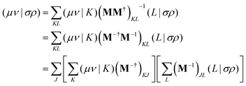 | (12) |
using the identity (
AB)
−1 =
B−1A−1 for square matrices
A and
B and
M−† = (
M†)
−1. Comparison with
eqn (6) yields the equation for determining the Cholesky vectors:
| |  | (13) |
Evaluating
eqn (13) can be done using efficient BLAS and LAPACK routines resulting in a superior efficiency compared the pivoting procedure.
For correlated calculations, a sequential transformation of the CVs into the basis of molecular orbitals (MOs)
| |  | (14) |
is performed. The corresponding MO integrals are expressed analogously as
| |  | (15) |
and may readily be used in a subsequent CC treatment.
2.3 Cholesky decomposition in finite-field CC theory
In CC theory,8,9,105,122–128 an exponential approach is chosen for the wave function| |  | (16) |
The exponential term can be represented by a series expansion as a sum of cluster operators ![[T with combining circumflex]](https://www.rsc.org/images/entities/i_char_0054_0302.gif) of different powers. The operators act on a reference determinant |Φ0〉, for which the HF wave function is usually chosen. The cluster operator
of different powers. The operators act on a reference determinant |Φ0〉, for which the HF wave function is usually chosen. The cluster operator ![[T with combining circumflex]](https://www.rsc.org/images/entities/i_char_0054_0302.gif) of an N-electron system is obtained as the sum of N excitation operators
of an N-electron system is obtained as the sum of N excitation operators ![[T with combining circumflex]](https://www.rsc.org/images/entities/i_char_0054_0302.gif) n:
n:| |  | (17) |
The excitation operators consist of the weighting coefficients, the amplitudes tI, and a string of quasiparticle creation operators ![[small mu, Greek, circumflex]](https://www.rsc.org/images/entities/i_char_e0b3.gif) I, i.e., â†a and âi. The indices a,b,c… as well as i,j,k… denote virtual and occupied orbitals, respectively. The CC energy and amplitude equations are given by
I, i.e., â†a and âi. The indices a,b,c… as well as i,j,k… denote virtual and occupied orbitals, respectively. The CC energy and amplitude equations are given by| | 〈Φ0|![[H with combining macron]](https://www.rsc.org/images/entities/i_char_0048_0304.gif) |Φ0〉 = ECC, |Φ0〉 = ECC, | (18) |
| | ΩI(t) = 〈ΦI|![[H with combining macron]](https://www.rsc.org/images/entities/i_char_0048_0304.gif) |Φ0〉 = 0 |Φ0〉 = 0 | (19) |
with ![[H with combining macron]](https://www.rsc.org/images/entities/i_char_0048_0304.gif) = e−
= e−![[T with combining circumflex]](https://www.rsc.org/images/entities/i_char_0054_0302.gif) Ĥe
Ĥe![[T with combining circumflex]](https://www.rsc.org/images/entities/i_char_0054_0302.gif) as the similarity-transformed Hamiltonian. Restriction of the cluster operator to contain only single and double excitations as well as restricting the projection space for the amplitude to the subspace of excited determinants 〈ΦI| obtained by the action of the cluster operator on the reference determinant leads to the CCSD truncation scheme.125–127
as the similarity-transformed Hamiltonian. Restriction of the cluster operator to contain only single and double excitations as well as restricting the projection space for the amplitude to the subspace of excited determinants 〈ΦI| obtained by the action of the cluster operator on the reference determinant leads to the CCSD truncation scheme.125–127
Within the CC2129–133 framework, an approximate CCSD formulation is achieved. By introducing the T1-transformed Hamiltonian ![[H with combining tilde]](https://www.rsc.org/images/entities/i_char_0048_0303.gif) = e−
= e−![[T with combining circumflex]](https://www.rsc.org/images/entities/i_char_0054_0302.gif) 1Ĥe
1Ĥe![[T with combining circumflex]](https://www.rsc.org/images/entities/i_char_0054_0302.gif) 1, the CCSD amplitude equations can be rewritten as
1, the CCSD amplitude equations can be rewritten as
| | 〈Φai|![[H with combining tilde]](https://www.rsc.org/images/entities/i_char_0048_0303.gif) + [ + [![[H with combining tilde]](https://www.rsc.org/images/entities/i_char_0048_0303.gif) , , ![[T with combining circumflex]](https://www.rsc.org/images/entities/i_char_0054_0302.gif) 2]|Φ0〉 = 0, 2]|Φ0〉 = 0, | (20) |
| |  | (21) |
A Møller–Plesset type partitioning of the Hamiltonian
Ĥ =
![[F with combining circumflex]](https://www.rsc.org/images/entities/i_char_0046_0302.gif)
+
Û is performed and only contributions through first order in perturbation theory are considered. The singles contributions are treated as zeroth order parameters. Hence, the singles equations retain their original form but the doubles amplitudes are approximated as
| | 〈Φabij|![[H with combining tilde]](https://www.rsc.org/images/entities/i_char_0048_0303.gif) + [ + [![[F with combining circumflex]](https://www.rsc.org/images/entities/i_char_0046_0302.gif) , ,![[T with combining circumflex]](https://www.rsc.org/images/entities/i_char_0054_0302.gif) 2]|Φ0〉 = 0. 2]|Φ0〉 = 0. | (22) |
To derive the working equations using the Cholesky representation, the two-electron integrals are substituted by the representation in
eqn (15) followed by reordering the contractions with the intent to
(1) Eliminate the storage of intermediates which have three or more virtual indices (e.g. VVVO and VVVV).
(2) Identify the optimal factorization by utilizing amplitude-transformed Cholesky vectors.
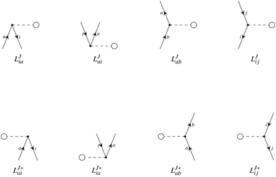
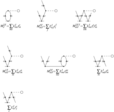
In the following, a generalization of the formulation in ref. 81 and 82 to the ff regime is presented. Here, care has to be taken as the symmetry  is lifted due to the loss of eightfold permutational symmetry. Additionally, an antisymmetric formulation of the intermediates is chosen which is exploited during the contraction with the amplitudes in our implementation. Regarding the underlying ff-(EOM)-CCSD equations, we refer to ref. 105 and 134. For the intermediates and amplitude-transformed Cholesky vectors the notation of Epifanovsky et al.81 was adopted: the numbers 1, 2, or 3 in the upper index mark a contraction with LJoo, LJov and LJvv vectors with either a CC amplitude T, or a right/left EOM-CC amplitude R/L. o and v stand for the occupied and virtual space, respectively. The expressions for the intermediates and transformed CVs are listed in Tables 1–4. The connection between the choice of the intermediates and a diagrammatic approach is described in the appendix.
Table 1
t-transformed Cholesky vectors
This is equivalent to the notation for the t1-transformed Hamiltonian  with with  and and  introduced in ref. 132. introduced in ref. 132.
|

|

|

|

|

|

|

|

|

|

|

|

|

|

|


|
|

|
|

|

|

|
τ
ab
ij
= tabij + ![[scr P, script letter P]](https://www.rsc.org/images/entities/char_e52f.gif) −ijtaitbj −ijtaitbj |
Table 2 List of (EOM)-CCSD intermediates
| Equation |
Scaling |
| CCSD |

|
|

|
|

|
|

|
V
3
O
3
|

|
V
3
O
3
|

|
V
4
O
2
|

|
V
2
O
4
|

|
V
3
O
3 + V2O4 |
| EOM-EE |

|
|

|
|

|
V
2
O
4
|

|
V
4
O
2
|

|
V
4
O
2
|
Table 3
r- and l-transformed Cholesky vectors
Table 4 List of left-hand side EOM-CCSD intermediates
The working equations for the CCSD single and double amplitudes are given as:
| | 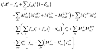 | (23) |
| | 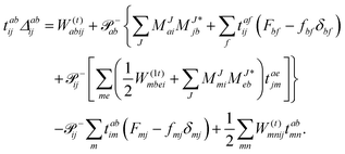 | (24) |
with the definitions
Δai =
fii −
faa and
Δabij =
fii +
fjj −
faa −
fbb, which equate to the orbital-energy difference for canonical orbitals,
i.e., Δ
εai =
εi −
εa and Δ
εabij =
εi +
εj −
εa −
εb. Within the CC2 scheme, in iteration
n the contributions
t(n−1)1 →
t(n)1 and
t(n−1)1 →
t(n)2 are calculated first and afterwards the immediate back contributions of the doubles
t(n)2 →
t(n)1 are accounted for similar to the discussion in ref.
135. While the singles equation retain their original form the doubles amplitudes simplify by keeping only the
t1 contributions:
| |  | (25) |
The final energy expression is
| |  | (26) |
Considering only the
![[scr O, script letter O]](https://www.rsc.org/images/entities/char_e52e.gif)
(
N6) terms which have to be calculated in every iteration this formulation of the CCSD equations (while neglecting spin and symmetry) scales as
for building the intermediates
W(t)abij,
W(1t)iabj, and
W(t)ijkl as well as the subsequent contraction of the latter two intermediates. Here,
O and
V correspond to the number of occupied and virtual orbitals, respectively. As already discussed in ref.
81, in comparison to a canonical CCSD implementation, one less contraction of type
O3V3 is required. Hence, in theory the CD implementation has the same scaling with a slightly smaller prefactor than the canonical algorithm. Still, the expensive particle–particle ladder term does not factorize well. For its implementation special care has to be taken to not fully store the
VVVV intermediate emerging from rebuilding partially transformed integrals
via
which is covered in more detail in Section 2.6. We note, however, that in practical applications the
N5 term (
V4NCH) often scales worse than the particle–particle ladder term (
V4O2) itself, when
NCH >
O2. Nevertheless, the implementation allows CCSD calculations at comparable timings but with significantly reduced memory requirements.
CD-CC2 factorizes very well and scales only with 2O2V2NCH FLOPs compared to canonical CC2 which scales as OV4 + 8O2V3 + 8O3V2 + O4V. Additionally, no VVVO or larger intermediate is needed at all, leading to much reduced memory demands.
2.4 Equation-of-motion-coupled-cluster theory
In the EOM-CC approach,8,134,136–144 the target state is obtained from a CC reference wave function| |  | (28) |
with the linear operator| |  | (29) |
![[small mu, Greek, circumflex]](https://www.rsc.org/images/entities/i_char_e0b3.gif) I generates the excited determinants ΦI of interest and
I generates the excited determinants ΦI of interest and ![[R with combining circumflex]](https://www.rsc.org/images/entities/i_char_0052_0302.gif) is defined for the particle-conserving electronically-excited and spin-flip states (EOM-EE,136,137 EOM-SF138,139), as
is defined for the particle-conserving electronically-excited and spin-flip states (EOM-EE,136,137 EOM-SF138,139), as| |  | (30) |
as well as for ionized (EOM-IP140)| |  | (31) |
and electron-attached states (EOM-EA141)| |  | (32) |
The EOM-CC eigenvalue equations are given as
| |  | (33) |
where the eigenvalue
Eexc is the excitation energy,
A is the CC-Jacobian,
142 and the eigenvectors
r contain the amplitudes of the operator
![[R with combining circumflex]](https://www.rsc.org/images/entities/i_char_0052_0302.gif)
. The matrix–vector product of the Jacobian with the EOM-CC amplitude vector is the sigma vector,
σ =
Ar, thereby referring to the usual notation of the Davidson algorithm.
145–147 Truncation of
![[T with combining circumflex]](https://www.rsc.org/images/entities/i_char_0054_0302.gif)
and
![[R with combining circumflex]](https://www.rsc.org/images/entities/i_char_0052_0302.gif)
at the same excitation level (here doubles) yields:
| | Eexcr0 = 〈Φ0|(![[H with combining macron]](https://www.rsc.org/images/entities/i_char_0048_0304.gif) ![[R with combining circumflex]](https://www.rsc.org/images/entities/i_char_0052_0302.gif) 1)c|Φ0〉 + 〈Φ0|( 1)c|Φ0〉 + 〈Φ0|(![[H with combining macron]](https://www.rsc.org/images/entities/i_char_0048_0304.gif) ![[R with combining circumflex]](https://www.rsc.org/images/entities/i_char_0052_0302.gif) 2)c|Φ0〉, 2)c|Φ0〉, | (34) |
| | Eexcrai = 〈Φai|(![[H with combining macron]](https://www.rsc.org/images/entities/i_char_0048_0304.gif) ![[R with combining circumflex]](https://www.rsc.org/images/entities/i_char_0052_0302.gif) 1)c|Φ0〉 + 〈Φai|( 1)c|Φ0〉 + 〈Φai|(![[H with combining macron]](https://www.rsc.org/images/entities/i_char_0048_0304.gif) ![[R with combining circumflex]](https://www.rsc.org/images/entities/i_char_0052_0302.gif) 2)c|Φ0〉, 2)c|Φ0〉, | (35) |
| | Eexcrabij = 〈Φabij|(![[H with combining macron]](https://www.rsc.org/images/entities/i_char_0048_0304.gif) ![[R with combining circumflex]](https://www.rsc.org/images/entities/i_char_0052_0302.gif) 1)c|Φ0〉 + 〈Φabij|( 1)c|Φ0〉 + 〈Φabij|(![[H with combining macron]](https://www.rsc.org/images/entities/i_char_0048_0304.gif) ![[R with combining circumflex]](https://www.rsc.org/images/entities/i_char_0052_0302.gif) 2)c|Φ0〉. 2)c|Φ0〉. | (36) |
The working equations for EOM-EE (![[R with combining circumflex]](https://www.rsc.org/images/entities/i_char_0052_0302.gif) =
= ![[R with combining circumflex]](https://www.rsc.org/images/entities/i_char_0052_0302.gif) EE) in the CD formalism are given for the r0 amplitude equations as
EE) in the CD formalism are given for the r0 amplitude equations as
| |  | (37) |
as well as the for
r1 amplitudes as
| |  | (38) |
and for the
r2 amplitudes as
| | 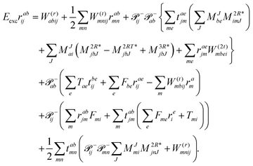 | (39) |
We note that compared to ref. 81 we redefined the following contribution:
| | 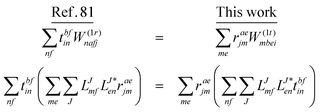 | (40) |
so that the intermediate
W(1t)mbei is independent of the EOM-CC amplitudes in contrast to
W(1r)nafj. Grouping of the former with
I(3i)abij yields
| |  | (41) |
This proves to be more efficient since another
V3O3 type contraction does not need to be re-evaluated in each iteration. In total, the scaling corresponds to
V4O2 + 2
V3O3 + 3
V2O4. In comparison, the canonical implementation scales as
V4O2 +
V3O3 +
V2O4. Thus, the Cholesky implementation comes with some drawback in terms of efficiency as compared to the canonical case due to the fact that
r-dependent intermediates such as
W(r)ijkl (responsible for 2
V2O4) and

(responsible for
V3O3) and their contractions with the cluster amplitudes have to be recomputed in each iteration to avoid the storage of
VVVV and
VVVO type intermediates, respectively. Likewise, the comments made for the
W(t)abij intermediate for ground state CC hold here as well for
W(r)abij.
2.4.1 Approximate EOM-coupled-cluster – EOM-EE-CC2.
As seen for the EOM-CCSD equations, a straightforward way to derive the EOM-CC2129–133 equations is to evaluate the Jacobian, i.e., the derivative of the CC2 amplitude equations with respect to the cluster amplitudes. For canonical orbitals the CC2-Jacobian is given as| | 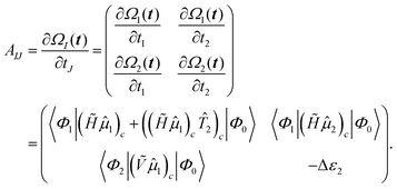 | (42) |
While the determining equations for the singles amplitudes are the same as in the full CCSD treatment, the doubles amplitudes are simply given as| | Eexcrabij = 〈Φabij|(Ṽ![[R with combining circumflex]](https://www.rsc.org/images/entities/i_char_0052_0302.gif) 1)c|Φ0〉 − Δεabijrabij 1)c|Φ0〉 − Δεabijrabij | (43) |
or rather| |  | (44) |
Within the CD approximation the EOM-EE-CC2 working equations are| | 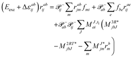 | (45) |
In analogy to CD-EOM-CCSD the scaling of CD-EOM-CC2 is 2O2V2NCH + O2V3 + O3V2 which is more expensive than the canonical implementation, i.e., 3O2V3 + 3O3V2, for O + V < NCH. As an advantage, the CD scheme does not require building any four-index intermediates. Thus the memory is in principle only limited by the storage of the amplitudes themselves. To be more precise, the EOM-CC2 amplitudes for double excitations can be partitioned out of the Davidson subspace – see also ref. 133. This allows to form the amplitudes temporarily and process them in batches. Consequently for CC2, the primary limitation on memory usage arises from the Cholesky vectors.
2.5 Left-hand side EOM-CC equations and properties
Since the Jacobian A in eqn (33) is a non-Hermitian matrix (due to the fact that the exponential of the cluster operator e![[T with combining circumflex]](https://www.rsc.org/images/entities/i_char_0054_0302.gif) is non-unitary), there exists also a left-hand side equation of the eigenvalue problem8,142to the same set of eigenvalues. These equations similarly describe linear deexciations via the operator
is non-unitary), there exists also a left-hand side equation of the eigenvalue problem8,142to the same set of eigenvalues. These equations similarly describe linear deexciations via the operator| |  | (47) |
In this case, the eigenvectors r and l are not simply Hermitian conjugates but form an biorthogonal set which can be normalized:| |  | (48) |
As mentioned above, the left-hand side equation does not have to be solved to evaluate the excitation energies. However, it has to be solved for the evaluation of properties.8,82,137,148,149 For example, (transition) dipole moments, can be expressed as biorthogonal expectation value| | μmn = 〈ΨmEOM|![[small mu, Greek, circumflex]](https://www.rsc.org/images/entities/i_char_e0b3.gif) |ΨnEOM〉 = 〈Φ0| |ΨnEOM〉 = 〈Φ0|![[L with combining circumflex]](https://www.rsc.org/images/entities/i_char_004c_0302.gif) me− me−![[T with combining circumflex]](https://www.rsc.org/images/entities/i_char_0054_0302.gif) ![[small mu, Greek, circumflex]](https://www.rsc.org/images/entities/i_char_e0b3.gif) e e![[T with combining circumflex]](https://www.rsc.org/images/entities/i_char_0054_0302.gif) ![[R with combining circumflex]](https://www.rsc.org/images/entities/i_char_0052_0302.gif) n|Φ0〉, n|Φ0〉, | (49) |
neglecting the contributions from the cluster amplitudes and orbital relaxation.150 For m ≠ n, this yields transition-dipole moments between the states m and n and single state dipole moments for m = n. A special case is m = n = 0 which is equivalent to the CC reference wave function. The CC ground state is a solution to the eigenvalue problem of EOM-EE, where r0 is set to 1 and all other amplitudes of higher excitations vanish.| | μ00 = 〈Φ0|![[L with combining circumflex]](https://www.rsc.org/images/entities/i_char_004c_0302.gif) 0 0![[small mu, Greek, macron]](https://www.rsc.org/images/entities/i_char_e0cd.gif) |Φ0〉 |Φ0〉 | (50) |
Thus, the problem reduces to the EOM left-hand-side solution for the ground state. This is formally equivalent to the Λ-equations in CC derivative theory7,8,151,152 with ![[L with combining circumflex]](https://www.rsc.org/images/entities/i_char_004c_0302.gif) 0 = (1 +
0 = (1 + ![[capital Lambda, Greek, circumflex]](https://www.rsc.org/images/entities/i_char_e0a8.gif) ), i.e. l0 = 1 for the ground state. For excited states, l0 can be chosen as 0, as biorthonormality is ensured by scaling the rest of the l vector. The transition-dipole moment between two arbitrary states is evaluated by summing over the dipole-moment integrals μ and the reduced one-particle transition-density matrix ρ
), i.e. l0 = 1 for the ground state. For excited states, l0 can be chosen as 0, as biorthonormality is ensured by scaling the rest of the l vector. The transition-dipole moment between two arbitrary states is evaluated by summing over the dipole-moment integrals μ and the reduced one-particle transition-density matrix ρ| |  | (51) |
The evaluation of one-electron reduced density matrix is unchanged in a Cholesky decomposed implementation. For reference of the working equations in the ff setting see ref. 149. Consequentially, the ground and excited-state properties require the solution of the EOM left-hand side equations. For CD-(EOM)-CCSD the l1 amplitudes are given by| | 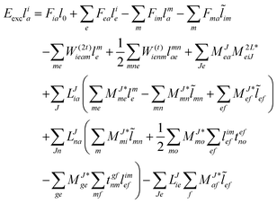 | (52) |
and l2 amplitudes by| | 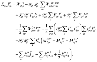 | (53) |
2.5.1 Approximate EOM-coupled-cluster – EOM-EE-CC2.
For CC2 the left-hand side equations are evaluated using the same strategy as for the right-hand side. According to the left-hand side eigenvalue problem in eqn (46), multiplication with the CC2-Jacobian of eqn (42) yields the equations| | Eexclia = 〈Φ0|(![[L with combining circumflex]](https://www.rsc.org/images/entities/i_char_004c_0302.gif) 2Ṽ)c|Φai〉 + 〈Φ0|( 2Ṽ)c|Φai〉 + 〈Φ0|(![[L with combining circumflex]](https://www.rsc.org/images/entities/i_char_004c_0302.gif) 1 1![[H with combining tilde]](https://www.rsc.org/images/entities/i_char_0048_0303.gif) )c + (( )c + ((![[L with combining circumflex]](https://www.rsc.org/images/entities/i_char_004c_0302.gif) 1 1![[H with combining tilde]](https://www.rsc.org/images/entities/i_char_0048_0303.gif) )c) )c)![[T with combining circumflex]](https://www.rsc.org/images/entities/i_char_0054_0302.gif) 2)c|Φai〉 2)c|Φai〉 | (54) |
and| |  | (55) |
Thus, for the left-hand side also the singles equations are altered by the CC2 approximation. Within the CD approximation the working equation are| | 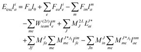 | (56) |
and| |  | (57) |
Thereby the scaling is identical to the right-hand side equations. Accordingly, the arguments given in the previous section hold here as well.
2.6 Implementation
Spin-integrated open-shell implementations of ground-state CCSD and CC2 as well as excited-state methods including EOM-CCSD (EE, SF, IP, EA) and the approximate EOM-CC2 (EE) method were implemented within the program package QCUMBRE.153 QCUMBRE is based on a string-based tensor contraction framework presented in ref. 134. A contraction is generally performed by casting it into an efficient matrix multiplication by tensor transpositions which is evaluated using BLAS.154 As the initial framework solely considered spin-symmetry, further development by Kitsaras144 enabled the exploitation of point-group symmetry via symmetry-blocked tensors.
In the following section, further improvements that have been added as part of this work are introduced. These improvements have been designed to enable the use of contractions in a more ‘black-box’ manner while aiming at maintaining a developer-friendly structure that allows straightforward implementation of working equations:
(a) Transpositions, despite scaling only with the tensor size, noticeably affect the total wall time due to their inherent cache inefficiency. Both input tensors require transposition to ensure the correct shape for the matrix multiplication step, and the output has to be transposed as well to obtain the target quantity. Consequently, to perform a tensor contraction, in the worst case, three tensor transpositions have to be performed. As the indices for a given contraction may align with the target indices for any of the transpositions the number of FLOPs required is dependent on whether the tensor is the left-hand side or right-hand side input of the contraction. To achieve an optimal and black-box contraction routine, it was extended by a mechanism that determines the order of the input tensors by minimizing a cost function.
(b) To further increase the efficiency, antisymmetry of the tensors is exploited fully, similarly to the ideas discussed in ref. 155 and 156. The coupled-cluster amplitudes and intermediates are antisymmetric with respect to permutation, i.e.,
| | | tabij = −tbaij = tbaji = −tabji. | (58) |
Thus, for any such quantity it is sufficient to save the block
a <
b and
i <
j. Exploiting this symmetry during the contractions such as in the particle–particle ladder term
| |  | (59) |
the required FLOPs are reduced by a factor of 6. Nonetheless, some care has to be taken for intermediates in which the tensors have to be partially (
eqn (60)) or fully (
eqn (61)) unpacked to perform the contraction:
| |  | (60) |
| |  | (61) |
(c) Additionally, as is standard practice for tensor contraction libraries, a parallelization of the most time-consuming steps in the tensor contraction workflow has been carried out. Thus, for QCUMBRE the tensor transpositions as well as the folding and unfolding of packed indices which precede the matrix multiplication step were parallelized. Furthermore, the zgemm routines employed for matrix multiplication are easily parallelized
via OpenMP
157 using the respective threaded BLAS libraries. In addition to the shared memory parallelization of the tensor contractions a massively parallel implementation of EOM using the message passing interface (MPI) was realized. As each root of EOM is independent of the others, it is possible to calculate them on different nodes. For a review of the developments for established quantum chemical packages handling field-free calculations we refer to ref.
158.
(d) For a memory-efficient implementation of CD-(EOM)-CCSD special care has to be taken to avoid the storage of any rank four tensor with three or more virtual indices e.g. VVVO and VVVV. The particle–particle-ladder-like terms W(t/r/l)abij as well as the EOM intermediate W(t)kaij need such quantities if implemented in a straightforward manner. In order to avoid the storage, an on-the-fly three tensor contraction routine was implemented that builds these contributions batch-wise, following the ideas of ref. 81. The batch is distributed such that a subset  is chosen so that the batch fits into the available memory to ensure optimal usage of memory and to minimize overhead. Calculations are thus in principle only limited by the size of OOVV quantities. The intermediate
  is then antisymmetrized and due to the fact that the full range of the index pair ef is kept, the antisymmetry can be exploited in the subsequent contraction to the target amplitude:
| |  | (62) |
Consequently, the intermediate
W(t)abef has to be calculated in every iteration which scales
V4NCH. In practical applications this
N5 term though often scales worse than the particle–particle ladder term itself since usually
NCH >
O2 resulting in an overhead for the CD implementation in general. Still, compared to a canonical CCSD implementation, the advantage is that all tensors can be held in memory and the required intermediates are calculated as needed. Therefore, no disk-IO is needed to read in the two-electron-integrals 〈
ab||
cd〉 which poses to be a bottleneck of canonical CCSD.
(e) Concurrent use of single-precision apart from the CD can be exploited to further lower memory and computation-time requirements with virtually no loss in accuracy as shown for many post-HF methods such as CD-MP2159 and CD-EOM-CCSD.160 If higher accuracy than that provided when using single-precision is needed, it is possible to first converge the amplitudes to single-precision and then switch to double precision for the last iterations to recover full accuracy.160,161
2.6.1 Validation.
Validation is straightforward by comparing results with a tight Cholesky threshold to the canonical implementation employing the full ERI. Therefore, the test set used in ref. 55 was employed.¶ In Fig. 1, the mean error of the ff-CD-HF energy, ff-CD-CCSD and CC2 correlation energy and the ff-CD-EOM-CCSD and CC2 excitation energy is plotted against the chosen Cholesky threshold. In accordance with previous results55 not only the error in the integrals but also the error in the energies is bound by the chosen Cholesky threshold (black line). Up to a Cholesky parameter of δ = 7, the error of all methods is strictly below the chosen threshold. In this case, the error for (EOM)-CC is approximately one order of magnitude smaller than that of the HF energy. Beyond this threshold the error is additionally constrained by the choice of the convergence criteria which is globally set to 10−7. Thus, the error in the EOM-CC energies becomes larger than the Cholesky threshold, while HF retains a good accuracy in the energy for orbital coefficients converged to 10−7.
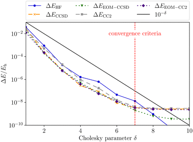 |
| | Fig. 1 Mean error of the ff-CD-HF energy (blue), ff-CD-CCSD and CC2 correlation energy (green and grey) and the ff-CD-EOM-CCSD and CC2 excitation energy (orange and indigo) as a function of the Cholesky parameter δ. The convergence criteria for HF, CC as well as EOM-CC were set to 10−7. | |
3 Applications
3.1 Computational details
The calculations have been performed using two program packages. The implementation of ff-CD-CC was done within the QCUMBRE153 program package which handles the post-HF treatment. It is interfaced to CFOUR162,163 with use of the MINT integral package.164 CFOUR handles the CD of the ERIs as well as the HF step. The following calculations on MgHe systems were performed using uncontracted (unc) augmented (aug) correlation consistent basis sets.165,166 The unc-aug-cc-pCVQZ167 basis was used for Mg and the unc-aug-cc-pVDZ basis was used for He if not stated otherwise and all electrons were correlated. The use of a larger basis set for helium produces only a small difference in the range of few percent, as validated in Table S1 in the ESI.† In the following we will discuss the 3P → 3S transition of triplet Mg mainly described by the excitation from 3p → 4s in different environments. Based on the symmetry of the studied system the respective states transform as different irreducible representations which are listed in Table 5. In all cases the states corresponding to the 3P−1 state was chosen as EOM-CC reference.
Table 5 Symmetry labels for the relevant states for 3p to 4s transition of Mg in its triplet state considered in this study: the Mg atom (SO(3)), the Mg atom in a magnetic field (C∞h), MgHe (C∞v), MgHe in a parallel (C∞) and perpendicular field (Cs) as well as MgHe12 in a field aligned along the C3 axis (C3h)
| SO(3) |
C
∞h
|
C
∞v
|
C
∞
|
C
s
|
C
3h
|
|
3P |
3Σu |
3Σ+ |
3Σ |
A′ |
A′ |
|
|
3Πu |
3Π |
3Π |
A′′ |
E′ |
|
|
|
|
|
A′ |
|
3.2 Pressure broadening of magnesium spectral lines
Assigning spectral lines for magnetic WDs is a non-trivial task. WDs are known to typically have dense helium or hydrogen atmospheres, and magnetic WDs in addition exhibit non-uniform surface-field distributions. Furthermore, even the coolest (magnetic) WDs have temperatures ranging from 4000 to 10![[thin space (1/6-em)]](https://www.rsc.org/images/entities/char_2009.gif) 000 K.6,168–171 The 3p → 4s (3P → 3S) transition for the Mg triplet is one of the most intense lines for metal-containing WDs.6,172 In ref. 6, this transition supported the assignment of a spectrum from a WD containing metals in its atmosphere (termed DZ) and a strong magnetic field of about 3000 T. Due to the high surface gravities of WDs, one would expect the metals to sink down quickly, leaving pure He/H atmospheres. The fact that metals are nonetheless found is linked to accretion from planetary disks into the atmosphere.172,173 This causes the star's atmosphere to be polluted by traces of metal species giving rise to distinct spectral lines. In order to study atoms and molecules under such extreme conditions it is crucial to model the surrounding environment, namely temperature, pressure, and density, as well as magnetic field, since they have a direct influence on the respective spectral lines.
000 K.6,168–171 The 3p → 4s (3P → 3S) transition for the Mg triplet is one of the most intense lines for metal-containing WDs.6,172 In ref. 6, this transition supported the assignment of a spectrum from a WD containing metals in its atmosphere (termed DZ) and a strong magnetic field of about 3000 T. Due to the high surface gravities of WDs, one would expect the metals to sink down quickly, leaving pure He/H atmospheres. The fact that metals are nonetheless found is linked to accretion from planetary disks into the atmosphere.172,173 This causes the star's atmosphere to be polluted by traces of metal species giving rise to distinct spectral lines. In order to study atoms and molecules under such extreme conditions it is crucial to model the surrounding environment, namely temperature, pressure, and density, as well as magnetic field, since they have a direct influence on the respective spectral lines.
Variations in the surface magnetic-field strength and relative orientation of the magnetic-field vector to the species of interest directly influence the transition wavelengths through alteration of the electronic structure. In the simplest model, to account for distribution of magnetic-field strengths over the star, a dipole is assumed, leading to a factor of two over the encountered field strengths. Due to their variation and due to the fact that the magnetic field strengths are not a priori known, field-dependent transition wavelengths (B–λ curves) are required to help assignment of spectra.
High-density atmospheres, where collisions are frequent, are prone to exhibit strong pressure-broadening effects. Especially due to the relatively low opacity of helium atmospheres at lower effective temperatures, observed photons can originate from deeper atmospheric layers with higher densities.172,174,175 Collisions between metal and surrounding atmosphere atoms alter the energy levels of the radiating metal atom and thus cause a shift as well as a broadening of the spectral lines in the WD's spectrum. The broadening arises from the fact that the distance between the radiating atom and atmosphere particles is not constant. Instead, it is distributed around a mean value dependent on pressure and temperature. Moreover, the individual energy levels involved in a transition are affected due to the interaction with the environment.176 The pressure effects cause both the shift as well as asymmetric line shapes and satellites as discussed, for example, in ref. 172. For a review on methods to model the spectral lines see also ref. 177. Generally, a parcel of gas at a specific temperature and number density of helium atoms is assumed. Within that parcel some helium atoms will collide with a radiator atom and consequentially the energy levels and transition dipole-moments of the radiator will be altered strongly. Statistically, other helium atoms will be further away and therefore will not significantly perturb the system. To calculate the line profile for this parcel of gas, integration over the distribution of atomic separations is performed. Consequently, only the diatomic potentials are needed to model the line shape.||
3.2.1 MgHe interaction.
The polarization by surrounding helium atoms can significantly affect the electronic structure of magnesium and thus warrants investigation in order to be able to model the spectral line position and shape. In this study, we investigate the pressure effects on the 3p → 4s (3P → 3S) transition for the Mg triplet perturbed by a dense helium atmosphere in an external magnetic field. A number of previous studies172,177–182 have already been conducted in the field-free case, where ref. 170 and 172 specifically deal with the Mg triplet transition of interest. Here, we will build upon the results of previous studies by expanding the discussion by the influence of an external magnetic field on the pressure effects:
We start our discussion on the Mg–He dimer in the field-free case. Due to the fact that the asymmetric broadening can be observed whether or not spin–orbit splittings are resolved within it,170,172 we neglect their contribution for our discussion.** Starting from the field-free case, the initial state for the isolated Mg atom in the 3P-state is described by the three degenerate p-orbitals. Introducing the helium atom into the system lowers the molecular symmetry to C∞v. As a result the former 3P-state splits into two degenerate bonding 3Π-states whose highest occupied molecular orbitals (HOMOs) are perpendicular to the bond axis. The 3Σ+ (3p0) state, with the HOMO oriented along the bond axis, is non bonding and higher in energy as shown in the central panel of Fig. 2. The transition wavelength of the Mg transition (3P → 3S) as a function of the distance to the helium atom is shown in Fig. 3 together with the total energies of the involved 3Π and 3Σ+ (4s) states. Note that the unperturbed transition wavelength in our calculation is about 5132 Å while the observed one is centred around 5174 Å.183 The difference is due to basis-set incompleteness errors, higher-order correlation effects, as well as relativistic effects. This discrepancy does not, however, impact the overall qualitative analysis as the focus is on energy shifts which are not expected to change significantly. Still, as already discussed in ref. 184, for fully quantitative predictions, composite schemes would need to be employed. These may include, as mentioned above, an extrapolation to the basis-set limit, higher-order correlation effects, and a shift to the NIST data to account for field-free scalar relativistic effects.
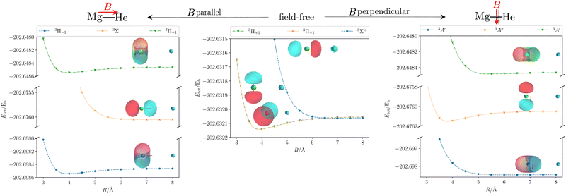 |
| | Fig. 2 Total energy Etot of the initial and first two final states of the MgHe triplet dimer without an external magnetic field (middle) and within a finite magnetic field of 0.05 B0 oriented parallel (left) and perpendicular (right) with respect to the Mg–He axis. The calculations were performed at the unc-aug-cc-pVTZ/CC3133 level of theory.a Additionally, the respective (complex) orbitals visualized via COrbit19144 are shown. Mg is depicted in green and He in blue. a![[thin space (1/6-em)]](https://www.rsc.org/images/entities/char_2009.gif) Note that an accuracy beyond CCSD is required to describe the dissociation limit of the degenerate Π and Σ states in a qualitatively correct manner. Note that an accuracy beyond CCSD is required to describe the dissociation limit of the degenerate Π and Σ states in a qualitatively correct manner. | |
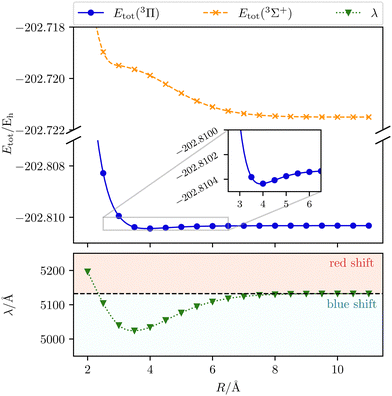 |
| | Fig. 3 The transition wavelength λ (3Π → 3Σ+) as well as the total initial-state energy Etot as a function of the Mg–He distance R. Calculated with CD-CCSD (δ = 5) using the unc-aug-cc-pCVQZ basis for Mg and the unc-aug-cc-pVDZ basis for He. | |
As the helium atom approaches an isolated magnesium atom, a blue shift arises in a gradual manner. Until a distance of 9.0 Å, the interaction is so weak that the change in the transition wavelength is smaller than 1 Å. Thus, up to this distance the system can be treated as non-interacting. The blue shift increases with the shortening of the Mg–He distance and reaches its maximum with a shift of about 108 Å at 3.5 Å. The main reason for the shift is the occurrence of a shoulder for smaller distances in the final 3Σ+ state. For shorter distances the transition wavelength rises up to an inter-atomic separation of 2.0 Å. While the initial state becomes more and more repulsive, the final state stays relatively unchanged, leading to a gradually increasing red shift relative to the unperturbed case.
Applying an external magnetic field changes the interaction in the MgHe dimer as shown in Fig. 2. In principle, all orientations of the magnetic field with respect to the bond axis should be taken into account. Here, we are picking out the two extreme cases, i.e., the parallel and the perpendicular orientations. In a magnetic field, the individual states are altered in the following ways: in the parallel orientation (C∞ symmetry), the bonding 3Π−1 state is stabilized and becomes the new ground state while the 3Π+1 state is destabilized. The non-bonding 3Σ-state has no orbital-Zeeman contribution and constitutes the first excited state. Conversely, in the perpendicular orientation (Cs symmetry) the non-bonding 3A′-state is stabilised and becomes the ground state while the first excited 3A′′-state is bonding. Increasing the magnetic field strength further, up to 0.20 B0, results in a slight destabilisation of the bound ground state in the parallel orientation. In the perpendicular orientation, when increasing the magnetic-field strength, the ground state becomes increasingly bound via the orbital-Zeeman interaction, as can be seen in Fig. 4.
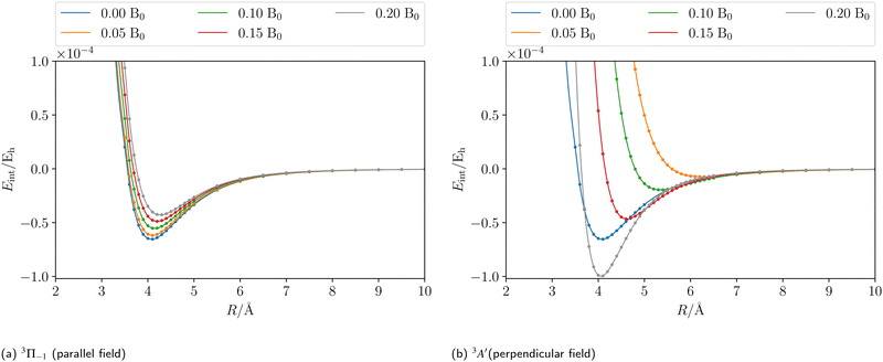 |
| | Fig. 4 The counterpoise corrected185,186 CCSD interaction energy of the initial state of the MgHe triplet dimer plotted as a function of the external magnetic field strength in a parallel (a) and perpendicular (b) orientation, respectively. The calculations were performed using the unc-aug-cc-pCVQZ basis for Mg and an unc-aug-cc-pVDZ basis for He. | |
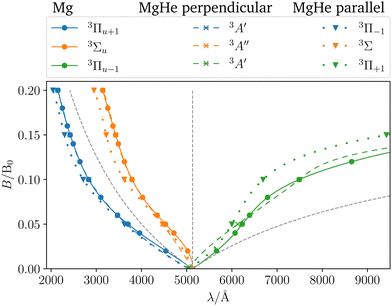
In order to assess the influence of the perturbing helium atom on the spectral lines of the magnesium triplet within a magnetic field the corresponding B–λ curves, i.e., the magnetic field strength plotted against the transition wavelength, are investigated as shown in Fig. 5. Note that we follow here the main character of the transition for isolated Mg such that the corresponding B–λ curves remain comparable even though formally there are a couple of avoided crossings with other states involved, particularly for higher magnetic-field strengths. For further details we refer to Fig. S1 and S2 in the ESI.† For the calculation, the respective equilibrium Mg–He distance within a given magnetic-field strength and orientation was chosen (see Table S13 in the ESI†). The p-orbitals, which are degenerate in the field-free case, split into three components resulting in large shifts in the transition wavelength. Additionally, due to the interplay of para- and diamagnetic effects induced by the external magnetic field, the lines vary in a non-trivial manner as compared to a simple orbital-Zeeman shift. Hence, ff methods are indispensable for interpreting spectra of strongly magnetic WDs as discussed in detail in ref. 6.††
 |
| | Fig. 5
B–λ curves for the transitions from the three former P-states. Three cases are distinguished. The isolated Mg atom is used as a reference (C∞h, solid lines) and is compared with the MgHe triplet dimer at the equilibrium geometry in the parallel (C∞, dotted lines) or the perpendicular (Cs, dashed lines) magnetic field. Calculated at the CD-CCSD (δ = 5) level using the unc-aug-cc-pCVQZ basis for Mg and an unc-aug-cc-pVDZ basis for He. Additionally, the simple orbital-Zeeman split (dashed gray lines) is also shown. | |
To assess the influence of the Helium atom on the transition in the magnetic field in more detail, the shift defined as the difference between the excitation energy of the isolated magnesium atom and the dimer in a parallel or perpendicular orientation is shown in Fig. 6. In the magnetic field, the following can be observed:
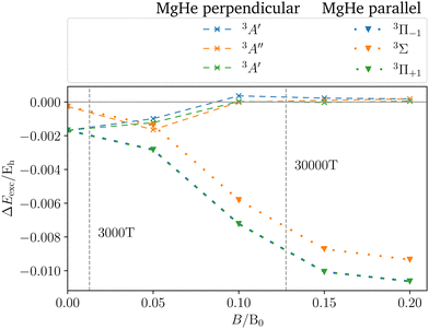 |
| | Fig. 6 Shift in the excitation energies ΔEexc induced by the helium atom for the three former P-states of the MgHe triplet dimer at the equilibrium geometry in a parallel (C∞, dotted) or perpendicular (Cs, dashed) magnetic field compared to the isolated Mg atom. For the changes in the transition wavelengths see also Fig. 5. | |
(1) The parallel orientation leads to very large blue shifts that increase with the magnetic field. This is explained by the fact that the 3Σ (4s) final state is destabilized‡‡ in the magnetic field as compared to the atomic case while the initial states remain mostly unchanged. In addition, it develops an increasingly large shoulder (see also Fig. S6 and S7 in the ESI†) which leads to larger shifts.
(2) Furthermore, in the parallel orientation, the curves for the shift in the transitions from the 3Π and 3Σ states, respectively, remain parallel. In the absence of a magnetic field, the influence of the Helium atom is stronger for transitions from the bonding 3Π states than for the non-bonding 3Σ+ (3p0) state. The difference is due to the fact that the excitation energy is evaluated at the equilibrium distance of the 3Π state at which the 3Σ+ (3p0) is repulsive. This in turn compensates to some degree the shoulder in the final 3Σ+ (4s) state (see Fig. 3). Thus, compared to the isolated Mg atom the transition from the bonding Π states is blue shifted as shown in Fig. 3 while the transition from 3Σ+ (3p0) is relatively unaffected. As the initial states remain mostly unchanged in the parallel field, so does their respective relative position. As such the shift for the transitions from the 3Σ+ (3p0) state evolves in parallel to those from the 3Π states when increasing the field strength.
(3) For the perpendicular orientation, the shifts vanish for large magnetic-field strengths. In this orientation, the states evolve in a comparable manner to the atomic case (see Fig. S1 in the ESI†) and the shoulder in the final state diminishes (see also Fig. S6 and S7 in the ESI†).§§
For the strongest magnetic field considered (0.20 B0) the shift due to the magnetic field in the perpendicular orientation is of the order of 0.2 mEh. In the parallel orientation shifts of about 10.6 mEh arise. These cases correspond to shifts in the wavelength of about 1 Å and 100 Å, respectively.
3.2.2 MgHe cluster.
The spectrum of a real white dwarf atmosphere is a result of the light emitted from various atmospheric layers including deeper layers which have significantly larger densities than the higher layers. It is quite typical for atmospheric layers that contribute to the observable spectra of WDs to reach densities of n(He) ≈ 1022 to 1023 cm−3, where the dense helium atmosphere shows fluid-like behaviour.174,181,187–189 For sufficiently large densities the average distance between the helium atoms and the magnesium is smaller than the collision cross section. Under such conditions, the radiating magnesium atom experiences numerous concurrent perturbations as it interacts with the adjacent helium atoms.
To account for such a perturbation, we also investigate Mg in an explicit solvation model (see Fig. 7). A magnesium atom is placed in an idealized hexagonal closed-packed structure, where all atoms within the cluster have the same interatomic distance. This may be a reasonable choice of configuration since helium crystallizes in a hcp structure under high pressures.¶¶ The hcp structure with a given radius can then be connected to a density of a helium atmosphere.
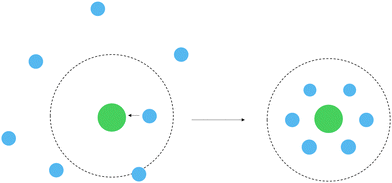 |
| | Fig. 7 Schematic depiction of the transition between the MgHe dimer model system to an explicit solvation model for large densities. The collision cross section is shown as dotted circle (Mg: green, He: blue). | |
In order to ensure that the treatment of the first coordination sphere (MgHe12) is sufficient to model the influence of the helium atmosphere in an explicit solvent model the contribution of the second shell is evaluated using the MgHe56 cluster depicted in Fig. 8 (using a lattice constant of 3 Å which corresponds to a density of 6.5 × 10²¹ atoms per cm3).|||| Therefore, a CD-CC2 calculation using the unc-aug-cc-pCVQZ basis on Mg and the unc-aug-cc-pVDZ basis on He was performed. We note that in this system with 781 basis functions the memory demand to store the full integrals in AO basis would correspond to almost 6 TB. This prohibitively large memory demand is diminished by using CD, which generates 3505 vectors (δ = 5) with a memory requirement of 34 GB. Overall, CD is mandatory in order to make a computational description of such systems at the ff-CC level feasible.
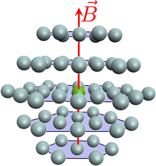 |
| | Fig. 8 Representation of a Mg atom (green) in a hcp lattice of He atoms (gray). Depicted are the first two shells forming a cluster of MgHe56, where 12 He atoms are in the first and 44 He atoms in the second shell. | |
Concerning the accuracy of ff-CC2, we note that as long as the states involved do not have a strong double-excitation character, the development of the excitation energies as a function of the magnetic field is reproduced faithfully. For MgHe12, the deviations between ff-EOM-CC2 and ff-EOM-CCSD, are around 1 mEh (see Tables S11 and S12 in the ESI†). For more details on the performance of ff-CC2, we refer the reader to ref. 133. Compared to MgHe12 the second layer contributes only 7 Å to the shift (see Table S12, ESI†). This is expected as (a) the polarization of the outer atoms is shielded by the first shell and (b) as shown in Fig. 3 the shift decreases rapidly with the distance to the Mg atom. This validates our approach to use the first coordination sphere as model system.
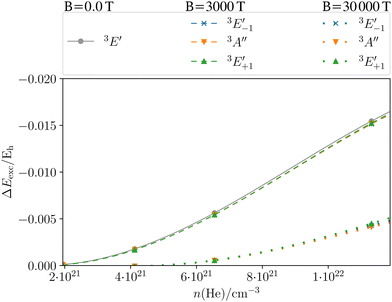
Fig. 9 shows the shift in the excitation energies for the MgHe12 cluster of the first coordination sphere oriented along the C3 axis as a function of helium density. The field-free case is shown in grey. Similar trends as for the MgHe dimer can be observed: for densities lower than 1 × 10²¹ atoms per cm3 the excitation energy and thereby also the spectral line is not shifted as the distance between Mg and He is too large. For denser atmospheres a blue shift, as expected from Fig. 3, arises which gets stronger with decreasing interatomic distance, i.e., increasing the density. Thereby, the transition wavelength shifts as a function of the density by several hundred Å (see also Fig. S4 in the ESI†) which corresponds to ten to thirteen times the effect of a single helium atom on the transition wavelength. However, the measured signals are emitted from various atmospheric layers, and hence from a distribution of temperatures and densities. Deeper layers with large densities can be expected to have a larger Rosseland mean opacity.190 The Rosseland mean opacity is a weighted mean of the total opacity over all wavelengths, which, among other factors, depends on the density, temperature, and composition (mass fractions) of the star. For our purposes, it can be understood as a measure of the number of photons that exit the stellar atmosphere.***![[thin space (1/6-em)]](https://www.rsc.org/images/entities/char_2009.gif) 191 Flux emitted from the deep, high-density layers of the atmosphere will undergo additional absorption and scattering, and only a fraction can be detected. Conversely, higher layers show an increased transparency where most of the flux is escaping the atmosphere and hence contribute to the observed spectrum. Additionally, the transition-dipole moment and hence the respective oscillator strength for this transition decreases as well with increasing density (see Table S11, ESI†). Consequently, the most intense signals originate from layers with moderate densities. The resulting overall line profile is thus not necessarily shifted by these large wavelength, but asymmetrically broadened.170,172
191 Flux emitted from the deep, high-density layers of the atmosphere will undergo additional absorption and scattering, and only a fraction can be detected. Conversely, higher layers show an increased transparency where most of the flux is escaping the atmosphere and hence contribute to the observed spectrum. Additionally, the transition-dipole moment and hence the respective oscillator strength for this transition decreases as well with increasing density (see Table S11, ESI†). Consequently, the most intense signals originate from layers with moderate densities. The resulting overall line profile is thus not necessarily shifted by these large wavelength, but asymmetrically broadened.170,172
 |
| | Fig. 9 Shift in the excitation energy ΔEexc = Eexc(ρ → 0) − Eexc(ρ) (in Hartree) at the CD-CCSD (δ = 5) level of the Mg triplet transition as a function of the helium density ρ of the MgHe12 (C3h) atmospheric model system in the field-free case as well as in a magnetic field of 3000 T and 30![[thin space (1/6-em)]](https://www.rsc.org/images/entities/char_2009.gif) 000 T oriented along the C3 axis. Employing the unc-aug-cc-pCVQZ on Mg and the unc-aug-cc-pVDZ basis on He. 000 T oriented along the C3 axis. Employing the unc-aug-cc-pCVQZ on Mg and the unc-aug-cc-pVDZ basis on He. | |
The dashed lines in Fig. 9 show the pressure dependence for a magnetic field of 3000 T. The three components show a very similar behavior as a function of the density as in the field-free case. For moderate field strengths, such as 3000 T, it thus seems justifiable to simply include the atmospheric pressure effects of the field-free case as a model for the line shapes in the magnetic field. For stronger magnetic field strengths of 30![[thin space (1/6-em)]](https://www.rsc.org/images/entities/char_2009.gif) 000 T (dotted lines) the behavior is similar for the three components but it is rather different from the cases discussed before. In fact, the shifts are much smaller and become relevant only for very large densities. The overall lower shift in the excitation energy may be explained in the following manner: as discussed previously for Fig. 6, an increasing vs. decreasing shift was found for the parallel and perpendicular orientations, respectively. For the MgHe12 cluster a superposition of these effect leads to an overall decrease of pressure effects for 30
000 T (dotted lines) the behavior is similar for the three components but it is rather different from the cases discussed before. In fact, the shifts are much smaller and become relevant only for very large densities. The overall lower shift in the excitation energy may be explained in the following manner: as discussed previously for Fig. 6, an increasing vs. decreasing shift was found for the parallel and perpendicular orientations, respectively. For the MgHe12 cluster a superposition of these effect leads to an overall decrease of pressure effects for 30![[thin space (1/6-em)]](https://www.rsc.org/images/entities/char_2009.gif) 000 T. For strong magnetic fields it may hence be reasonable to disregard the pressure effects except for very large densities.
000 T. For strong magnetic fields it may hence be reasonable to disregard the pressure effects except for very large densities.
Note however that because of the non-linear scale, if the shift is expressed in transition wavelengths (see Fig. S4 in the ESI†), the differences in the shift are more pronounced. In particular, the  component leads to much larger shifts than the other components. Again, for a quantitative prediction, composite schemes would need to be employed.
In this first-order approach in which we are using a static model system, insights into the influence of the atmosphere on the Mg transitions are gained. Going a step further could imply using a QM/MM approach for a dynamic description which can capture the effects of an arbitrary magnetic-field orientation at a given temperature and pressure while retaining the needed high level accuracy at the radiating Mg atom which will be the subject of further studies.
4 Conclusion
In this work we introduced the implementation of ff ground and excited-state CC methods exploiting the CD representation of the ERI (ff-CD-CC). The ff-CD-CC scheme allows to perform highly accurate calculations for atoms and molecules subjected to an external magnetic fields as can be found on magnetic WDs. By significantly reducing memory requirements, the CD tackles computational bottlenecks, enabling the investigation of systems which were previously computationally not feasible.
Assigning spectra from magnetic white dwarf stars requires very accurate predictions. It is a non-trivial task as such stars exhibit dense atmospheres, non-uniform strong magnetic fields, and a wide temperature range. These factors directly influence the spectral line shapes of atoms and molecules, making accurate modeling challenging. We showed that these developments enabled the study of pressure broadening of magnesium spectral lines on magnetic WDs. Furthermore, we discussed the influence of an external magnetic field and the considerable differences between the parallel and perpendicular orientations. In the MgHe system, the change in excitation energies with respect to the magnetic-field strength shows that the pressure shift due to He increases in parallel and decreases in perpendicular orientations. Lastly, we employed a cluster model to consider a more realistic scenario for high-density helium atmospheres. Particularly for treating the cluster, CD techniques becomes crucial. The analysis showed that for 3000 T pressure effects in the field-free case are comparable to the effects in magnetic fields which can justify incorporating pressure effects from the field-free case as approximation for line shapes in magnetic fields.
However, this approximation may not hold for stronger magnetic fields of, for example, 30![[thin space (1/6-em)]](https://www.rsc.org/images/entities/char_2009.gif) 000 T where the magnitude of the pressure effect on the excitation energies is decreased drastically.
000 T where the magnitude of the pressure effect on the excitation energies is decreased drastically.
Overall, this study shows the complex interplay between magnetic fields and pressure effects, and their influence on the spectral lines of magnesium. Further investigations, including dynamic descriptions of the environment and inclusion of temperature effects, are necessary to gain a conclusive understanding of matter in magnetic WDs.
Data availability
The data that supports the findings of this study are available within the article and its ESI.†
Conflicts of interest
The authors have no conflicts to disclose.
Appendices
A Diagrammatic approach
In the diagrammatic sense, let a pair of Cholesky vectors be described by one-electron operators. Thus, a vector and its complex conjugate can be defined as:
hence any (non-antisymmetrized) integral e.g. 〈ij|ab〉 can be represented as
where the left vector is read as
LJout,in and the right vector is defined as

. Thus, the intermediates can be understood as the contractions
B Working equations for EOM-EA and IP
For EOM-EA (![[R with combining circumflex]](https://www.rsc.org/images/entities/i_char_0052_0302.gif) =
= ![[R with combining circumflex]](https://www.rsc.org/images/entities/i_char_0052_0302.gif) EA) the amplitudes equate to
EA) the amplitudes equate to| |  | (63) |
and| | 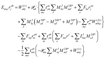 | (64) |
In analogy to EOM-EE the intermediate of ref. 81I(3i)iab is redefined and added to I(1i)iab resulting in| |  | (65) |
Thus, the scaling is overall ![[scr O, script letter O]](https://www.rsc.org/images/entities/char_e52e.gif) (N5) for CD-EOM-EA-CCSD and equates to V4NCH + OV4 + 2O2V3 + 2O2V2 which is to be compared to OV4 + O2V3 for the canonical implementation. As for EOM-EE from the overhead due to recalculation more flops are required but overall memory requirements decrease. The working equations for EOM-IP (
(N5) for CD-EOM-EA-CCSD and equates to V4NCH + OV4 + 2O2V3 + 2O2V2 which is to be compared to OV4 + O2V3 for the canonical implementation. As for EOM-EE from the overhead due to recalculation more flops are required but overall memory requirements decrease. The working equations for EOM-IP (![[R with combining circumflex]](https://www.rsc.org/images/entities/i_char_0052_0302.gif) =
= ![[R with combining circumflex]](https://www.rsc.org/images/entities/i_char_0052_0302.gif) IP) are
IP) are| |  | (66) |
and| | 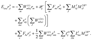 | (67) |
Again in contrast to ref. 81I(2i)ija is redefined and added to I(1i)ija which results in| |  | (68) |
For the cost of saving an additional VVOO type intermediate 2O2V2NCH + O3V2 + O2V3 flops are being saved per iteration. Thus, for EOM-IP the scaling of our CD implementation is identical to the canonical one. Both scale as O3V2 + O4V. In the same manner the l1 and l2 amplitudes for EOM-EA using the intermediates form Tables 6 and 7 are given as| | 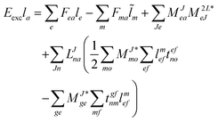 | (69) |
and| | 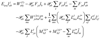 | (70) |
Table 6 CCSD-EOM-EA intermediates
| EOM-EA |
| Equation |
Scaling |

|
V
2
O
3
|

|
V
4
O
|

|
V
4
O
|
Table 7
r- and l-transformed Cholesky vectors
EOM-IP yields the amplitude equations
| |  | (71) |
and
| | 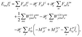 | (72) |
respectively.
Acknowledgements
The authors thank Jürgen Gauss, Filippo Lipparini, and Mark Hollands for helpful discussions. This work has been supported by the Deutsche Forschungsgemeinschaft (DFG) via project B05 of the TRR 146 “Multiscale Simulation Methods for Soft Matter Systems” and via Grant No. STO 1239/1-1.
Notes and references
- J. C. Kemp, J. B. Swedlund, J. D. Landstreet and J. R. P. Angel, Astrophys. J., 1970, 161, L77 CrossRef.
- S. Jordan, P. Schmelcher, W. Becken and W. Schweizer, Astron. Astrophys., 1998, 336, L33–L36 CAS.
- W. Becken, P. Schmelcher and F. K. Diakonos, J. Phys. B: At., Mol. Opt. Phys., 1999, 32, 1557–1584 CrossRef CAS.
- D. T. Wickramasinghe and L. Ferrario, Publ. Astron. Soc. Pac., 2000, 112, 873–924 CrossRef.
- S. O. Kepler, I. Pelisoli, S. Jordan, S. J. Kleinman, D. Koester, B. Külebi, V. Peçanha, B. G. Castanheira, A. Nitta, J. E. S. Costa, D. E. Winget, A. Kanaan and L. Fraga, Mon. Not. R. Astron. Soc., 2013, 429, 2934–2944 CrossRef.
- M. A. Hollands, S. Stopkowicz, M.-P. Kitsaras, F. Hampe, S. Blaschke and J. J. Hermes, Mon. Not. R. Astron. Soc., 2023, 520, 3560–3575 CrossRef CAS.
-
J. Gauss, in Modern Methods and Algorithms of Quantum Chemistry, ed. J. Grotendorst, John von Neumann Institute for Computing, Jülich, 2000, vol. 3, pp. 541–592 Search PubMed.
-
I. Shavitt and R. J. Bartlett, Many-body methods in chemistry and physics: MBPT and coupled-cluster theory, Cambridge University Press, Cambridge, England, 2009 Search PubMed.
-
T. D. Crawford and H. F. Schaefer, in Reviews in Computational Chemistry, ed. K. B. Lipkowitz and D. B. Boyd, John Wiley & Sons, Inc., New York, 2000, vol. 14, pp. 33–136 Search PubMed.
- S. Sæbø and P. Pulay, Chem. Phys. Lett., 1985, 113, 13–18 CrossRef.
- S. Sæbø and P. Pulay, Annu. Rev. Phys. Chem., 1993, 44, 213–236 CrossRef.
- S. F. Boys, Rev. Mod. Phys., 1960, 32, 296–299 CrossRef CAS.
- J. M. Foster and S. F. Boys, Rev. Mod. Phys., 1960, 32, 300–302 CrossRef CAS.
- C. Edmiston and K. Ruedenberg, Rev. Mod. Phys., 1963, 35, 457–464 CrossRef CAS.
- J. Pipek and P. G. Mezey, J. Chem. Phys., 1989, 90, 4916–4926 CrossRef CAS.
- O. Sinanoǧlu, Adv. Chem. Phys., 1964, 6, 315–412 CrossRef.
- R. K. Nesbet, Adv. Chem. Phys., 1965, 9, 321–363 CrossRef.
- P. Pulay, Chem. Phys. Lett., 1983, 100, 151–154 CrossRef CAS.
- C. Hampel and H.-J. Werner, J. Chem. Phys., 1996, 104, 6286–6297 CrossRef CAS.
- M. Schütz and H.-J. Werner, J. Chem. Phys., 2001, 114, 661 CrossRef.
- T. Korona and H.-J. Werner, J. Chem. Phys., 2003, 118, 3006–3019 CrossRef CAS.
- M. Schütz, Phys. Chem. Chem. Phys., 2002, 4, 3941–3947 RSC.
- D. Kats, T. Korona and M. Schütz, J. Chem. Phys., 2006, 125, 104106 CrossRef PubMed.
- F. Neese, F. Wennmohs and A. Hansen, J. Chem. Phys., 2009, 130, 114108 CrossRef PubMed.
- P.-O. Löwdin, Phys. Rev., 1955, 97, 1474–1489 CrossRef.
- C. Edmiston and M. Krauss, J. Chem. Phys., 1966, 45, 1833–1839 CrossRef CAS.
- W. Meyer, Int. J. Quantum Chem., 1971, 5, 341–348 CrossRef.
- F. Neese, A. Hansen and D. G. Liakos, J. Chem. Phys., 2009, 131, 064103 CrossRef PubMed.
- C. Riplinger and F. Neese, J. Chem. Phys., 2013, 138, 034106 CrossRef PubMed.
- C. Riplinger, P. Pinski, U. Becker, E. F. Valeev and F. Neese, J. Chem. Phys., 2016, 144, 024109 CrossRef PubMed.
- A. K. Dutta, F. Neese and R. Izsák, J. Chem. Phys., 2016, 145, 034102 CrossRef PubMed.
- A. K. Dutta, M. Saitow, C. Riplinger, F. Neese and R. Izsák, J. Chem. Phys., 2018, 148, 244101 CrossRef PubMed.
- A. K. Dutta, M. Saitow, B. Demoulin, F. Neese and R. Izsák, J. Chem. Phys., 2019, 150, 164123 CrossRef PubMed.
- K. Kitaura, E. Ikeo, T. Asada, T. Nakano and M. Uebayasi, Chem. Phys. Lett., 1999, 313, 701–706 CrossRef CAS.
- D. G. Fedorov and K. Kitaura, J. Chem. Phys., 2005, 123, 134103 CrossRef PubMed.
- D. G. Fedorov and K. Kitaura, J. Phys. Chem. A, 2007, 111, 6904–6914 CrossRef CAS PubMed.
- D. W. Zhang and J. Z. H. Zhang, J. Chem. Phys., 2003, 119, 3599–3605 CrossRef CAS.
- A. Warshel and M. Karplus, J. Am. Chem. Soc., 1972, 94, 5612–5625 CrossRef CAS.
- A. Warshel and M. Levitt, J. Mol. Biol., 1976, 103, 227–249 CrossRef CAS PubMed.
- M. Svensson, S. Humbel, R. D. J. Froese, T. Matsubara, S. Sieber and K. Morokuma, J. Phys. Chem., 1996, 100, 19357–19363 CrossRef CAS.
- J. L. Whitten, J. Chem. Phys., 1973, 58, 4496–4501 CrossRef CAS.
- E. Baerends, D. Ellis and P. Ros, Chem. Phys., 1973, 2, 41–51 CrossRef CAS.
- B. I. Dunlap, J. W. D. Connolly and J. R. Sabin, J. Chem. Phys., 1979, 71, 3396–3402 CrossRef CAS.
- O. Vahtras, J. Almlöf and M. W. Feyereisen, Chem. Phys. Lett., 1993, 213, 514–518 CrossRef CAS.
- M. Feyereisen, G. Fitzgerald and A. Komornicki, Chem. Phys. Lett., 1993, 208, 359–363 CrossRef CAS.
- A. Komornicki and G. Fitzgerald, J. Chem. Phys., 1993, 98, 1398–1421 CrossRef CAS.
- B. Dunlap, THEOCHEM, 2000, 501–502, 221–228 CrossRef CAS.
- B. Dunlap, THEOCHEM, 2000, 529, 37–40 CrossRef CAS.
- B. I. Dunlap, Phys. Chem. Chem. Phys., 2000, 2, 2113–2116 RSC.
- B. I. Dunlap, J. Phys. Chem. A, 2003, 107, 10082–10089 CrossRef CAS.
- N. H. F. Beebe and J. Linderberg, Int. J. Quantum Chem., 1977, 12, 683–705 CrossRef CAS.
- H. Koch, A. Sánchez de Merás and T. Bondo Pedersen, J. Chem. Phys., 2003, 118, 9481–9484 CrossRef CAS.
- S. D. Folkestad, E. F. Kjønstad and H. Koch, J. Chem. Phys., 2019, 150, 194112 CrossRef PubMed.
- T. Zhang, X. Liu, E. F. Valeev and X. Li, J. Phys. Chem. A, 2021, 125, 4258–4265 CrossRef CAS PubMed.
- S. Blaschke and S. Stopkowicz, J. Chem. Phys., 2022, 156, 044115 CrossRef CAS PubMed.
- J. Gauss, S. Blaschke, S. Burger, T. Nottoli, F. Lipparini and S. Stopkowicz, Mol. Phys., 2022, 121, e2101562 CrossRef.
- K. Eichkorn, O. Treutler, H. Öhm, M. Häser and R. Ahlrichs, Chem. Phys. Lett., 1995, 240, 283–290 CrossRef CAS.
- K. Eichkorn, F. Weigend, O. Treutler and R. Ahlrichs, Theor. Chem. Acc., 1997, 97, 119–124 Search PubMed.
- F. Weigend, M. Häser, H. Patzelt and R. Ahlrichs, Chem. Phys. Lett., 1998, 294, 143–152 CrossRef CAS.
- F. Weigend, Phys. Chem. Chem. Phys., 2006, 8, 1057–1065 RSC.
- F. Weigend, Phys. Chem. Chem. Phys., 2002, 4, 4285–4291 RSC.
- F. Weigend, J. Comput. Chem., 2007, 29, 167–175 CrossRef PubMed.
- F. Aquilante, R. Lindh and T. Bondo Pedersen, J. Chem. Phys., 2007, 127, 114107 CrossRef PubMed.
- F. Aquilante, L. Gagliardi, T. Bondo Pedersen and R. Lindh, J. Chem. Phys., 2009, 130, 154107 CrossRef PubMed.
- G. L. Stoychev, A. A. Auer and F. Neese, J. Chem. Theory Comput., 2017, 13, 554–562 CrossRef CAS PubMed.
- S. Lehtola, J. Chem. Theory Comput., 2021, 17, 6886–6900 CrossRef CAS PubMed.
- S. Lehtola, J. Chem. Theory Comput., 2023, 19, 6242–6254 CrossRef CAS PubMed.
- T. Bondo Pedersen, F. Aquilante and R. Lindh, Theor. Chem. Acc., 2009, 124, 1–10 Search PubMed.
-
F. Aquilante, L. Boman, J. Boström, H. Koch, R. Lindh, A. Sánchez de Merás and T. Bondo Pedersen, in Linear-Scaling Techniques in Computational Chemistry and Physics, ed. R. Zaleśny, M. G. Papadopoulos, P. G. Mezey and J. Leszczynski, Springer, Netherlands, 2011, ch. 13, pp. 301–343 Search PubMed.
- F. Aquilante and T. Bondo Pedersen, Chem. Phys. Lett., 2007, 449, 354–357 CrossRef CAS.
- H. Koch, A. Sánchez de Merás and T. Bondo Pedersen, J. Chem. Phys., 2008, 129, 024113 CrossRef PubMed.
- F. Aquilante, P.-Å. Malmqvist, T. Bondo Pedersen, A. Ghosh and B. O. Roos, J. Chem. Theory Comput., 2008, 4, 694–702 CrossRef CAS PubMed.
- F. Aquilante, R. Lindh and T. Bondo Pedersen, J. Chem. Phys., 2008, 129, 034106 CrossRef PubMed.
- J. Boström, V. Veryazov, F. Aquilante, T. Bondo Pedersen and R. Lindh, Int. J. Quantum Chem., 2013, 114, 321–327 CrossRef.
- M. G. Delcey, T. Bondo Pedersen, F. Aquilante and R. Lindh, J. Chem. Phys., 2015, 143, 044110 CrossRef PubMed.
- S. Burger, F. Lipparini, J. Gauss and S. Stopkowicz, J. Chem. Phys., 2021, 155, 074105 CrossRef CAS PubMed.
- T. Nottoli, J. Gauss and F. Lipparini, Mol. Phys., 2021, 119, e1974590 CrossRef.
- T. Nottoli, J. Gauss and F. Lipparini, J. Chem. Theory Comput., 2021, 17, 6819–6831 CrossRef CAS PubMed.
- A. Ünal and U. Bozkaya, J. Chem. Theory Comput., 2022, 18, 1489–1500 CrossRef PubMed.
- T. Nottoli, S. Burger, S. Stopkowicz, J. Gauss and F. Lipparini, J. Chem. Phys., 2022, 157, 084122 CrossRef CAS PubMed.
- E. Epifanovsky, D. Zuev, X. Feng, K. Khistyaev, Y. Shao and A. I. Krylov, J. Chem. Phys., 2013, 139, 134105 CrossRef PubMed.
- X. Feng, E. Epifanovsky, J. Gauss and A. I. Krylov, J. Chem. Phys., 2019, 151, 014110 CrossRef PubMed.
- T. Nottoli, J. Gauss and F. Lipparini, J. Chem. Phys., 2023, 159, 231101 CrossRef CAS PubMed.
- C. Zhang, F. Lipparini, S. Stopkowicz, J. Gauss and L. Cheng, J. Chem. Theory Comput., 2024, 20, 787–798 CrossRef CAS PubMed.
- T. Uhlířová, D. Cianchino, T. Nottoli, F. Lipparini and J. Gauss, J. Phys. Chem. A, 2024, 128, 8292–8303 CrossRef PubMed.
- T. B. Pedersen, A. M. J. S. de Merás and H. Koch, J. Chem. Phys., 2004, 120, 8887–8897 CrossRef CAS PubMed.
- A. K. Schnack-Petersen, H. Koch, S. Coriani and E. F. Kjønstad, J. Chem. Phys., 2022, 156, 244111 CrossRef CAS PubMed.
- E. G. Hohenstein, S. I. L. Kokkila, R. M. Parrish and T. J. Martínez, J. Chem. Phys., 2013, 138, 124111 CrossRef PubMed.
- E. G. Hohenstein, S. I. L. Kokkila, R. M. Parrish and T. J. Martínez, J. Phys. Chem. B, 2013, 117, 12972–12978 CrossRef CAS PubMed.
- E. G. Hohenstein, R. M. Parrish, C. D. Sherrill and T. J. Martínez, J. Chem. Phys., 2012, 137, 221101 CrossRef PubMed.
- R. M. Parrish, C. D. Sherrill, E. G. Hohenstein, S. I. L. Kokkila and T. J. Martínez, J. Chem. Phys., 2014, 140, 181102 CrossRef PubMed.
- A. Datar and D. A. Matthews, J. Chem. Theory Comput., 2024, 20, 708–720 CrossRef CAS PubMed.
- J. Almlöf, Chem. Phys. Lett., 1991, 181, 319–320 CrossRef.
- M. Häser and J. Almlöf, J. Chem. Phys., 1992, 96, 489–494 CrossRef.
- H. Koch and A. Sánchez de Merás, J. Chem. Phys., 2000, 113, 508–513 CrossRef CAS.
- J. L. Cacheiro, T. B. Pedersen, B. Fernández, A. S. D. Merás and H. Koch, Int. J. Quantum Chem., 2010, 111, 349–355 CrossRef.
- T. Kinoshita, O. Hino and R. J. Bartlett, J. Chem. Phys., 2003, 119, 7756–7762 CrossRef CAS.
- O. Hino, T. Kinoshita and R. J. Bartlett, J. Chem. Phys., 2004, 121, 1206–1213 CrossRef CAS PubMed.
- R. M. Parrish, Y. Zhao, E. G. Hohenstein and T. J. Martínez, J. Chem. Phys., 2019, 150, 164118 CrossRef PubMed.
- E. G. Hohenstein, Y. Zhao, R. M. Parrish and T. J. Martínez, J. Chem. Phys., 2019, 151, 164121 CrossRef PubMed.
- E. G. Hohenstein, B. S. Fales, R. M. Parrish and T. J. Martínez, J. Chem. Phys., 2022, 156, 054102 CrossRef CAS PubMed.
- M. Lesiuk, J. Comput. Chem., 2019, 40, 1319–1332 CrossRef CAS PubMed.
- M. Lesiuk, J. Chem. Phys., 2022, 156, 064103 CrossRef CAS PubMed.
- A. Jiang, J. M. Turney and H. F. Schaefer, J. Chem. Theory Comput., 2023, 19, 1476–1486 CrossRef CAS PubMed.
- S. Stopkowicz, J. Gauss, K. K. Lange, E. I. Tellgren and T. Helgaker, J. Chem. Phys., 2015, 143, 074110 CrossRef PubMed.
- H. Åström and S. Lehtola, J. Phys. Chem. A, 2023, 127, 10872–10888 CrossRef PubMed.
- C. Aldrich and R. L. Greene, Phys. Status Solidi B, 1979, 93, 343–350 CrossRef CAS.
- P. Schmelcher, L. S. Cederbaum and H.-D. Meyer, Phys. Rev. A: At., Mol., Opt. Phys., 1988, 38, 6066–6079 CrossRef CAS PubMed.
- W. Zhu and S. B. Trickey, J. Chem. Phys., 2017, 147, 244108 CrossRef PubMed.
- R. D. Reynolds and T. Shiozaki, Phys. Chem. Chem. Phys., 2015, 17, 14280–14283 RSC.
- R. D. Reynolds, T. Yanai and T. Shiozaki, J. Chem. Phys., 2018, 149, 014106 CrossRef PubMed.
- A. Pausch and W. Klopper, Mol. Phys., 2020, 118, e1736675 CrossRef.
- C. Holzer, A. Pausch and W. Klopper, Front. Chem., 2021, 9, 746162 CrossRef CAS PubMed.
- T. J. P. Irons, G. David and A. M. Teale, J. Chem. Theory Comput., 2021, 17, 2166–2185 CrossRef CAS PubMed.
- A. Pausch and C. Holzer, J. Phys. Chem. Lett., 2022, 13, 4335–4341 CrossRef CAS PubMed.
- A. Pausch, C. Holzer and W. Klopper, J. Chem. Theory Comput., 2022, 18, 3747–3758 CrossRef CAS PubMed.
- B. T. Speake, T. J. P. Irons, M. Wibowo, A. G. Johnson, G. David and A. M. Teale, J. Chem. Theory Comput., 2022, 18, 7412–7427 CrossRef CAS PubMed.
- F. London, J. Phys. Radium, 1937, 8, 397–409 CrossRef CAS.
- E. I. Tellgren, A. Soncini and T. Helgaker, J. Chem. Phys., 2008, 129, 154114 CrossRef PubMed.
- T. J. P. Irons, J. Zemen and A. M. Teale, J. Chem. Theory Comput., 2017, 13, 3636–3649 CrossRef CAS PubMed.
- S. Blaschke, S. Stopkowicz and A. Pausch, J. Chem. Phys., 2024, 161, 024117 CrossRef CAS PubMed.
- J. Čžek, J. Chem. Phys., 1966, 45, 4256–4266 CrossRef.
- J. Čžek, Adv. Chem. Phys., 1969, 14, 35–89 CrossRef.
- R. J. Bartlett and G. D. Purvis, Int. J. Quantum Chem., 1978, 14, 561–581 CrossRef CAS.
- G. D. Purvis and R. J. Bartlett, J. Chem. Phys., 1982, 76, 1910–1918 CrossRef CAS.
- J. F. Stanton, J. Gauss, J. D. Watts and R. J. Bartlett, J. Chem. Phys., 1991, 94, 4334–4345 CrossRef CAS.
- R. J. Bartlett and M. Musiał, Rev. Mod. Phys., 2007, 79, 291 CrossRef CAS.
- S. Stopkowicz, Int. J. Quantum Chem., 2018, 118, e25391 CrossRef.
- O. Christiansen, H. Koch and P. Jørgensen, Chem. Phys. Lett., 1995, 243, 409–418 CrossRef CAS.
- O. Christiansen, H. Koch and P. Jørgensen, J. Chem. Phys., 1995, 103, 7429–7441 CrossRef CAS.
- H. Koch, O. Christiansen, P. Jørgensen, A. Sánchez de Merás and T. Helgaker, J. Chem. Phys., 1997, 106, 1808–1818 CrossRef CAS.
- C. Hättig and F. Weigend, J. Chem. Phys., 2000, 113, 5154 CrossRef.
- M.-P. Kitsaras, L. Grazioli and S. Stopkowicz, J. Chem. Phys., 2024, 160, 094112 CrossRef CAS PubMed.
- F. Hampe and S. Stopkowicz, J. Chem. Phys., 2017, 146, 154105 CrossRef PubMed.
- D. A. Matthews and J. F. Stanton, J. Chem. Phys., 2015, 143, 204103 CrossRef PubMed.
- J. Geertsen, M. Rittby and R. J. Bartlett, Chem. Phys. Lett., 1989, 164, 57–62 CrossRef CAS.
- J. F. Stanton and R. J. Bartlett, J. Chem. Phys., 1993, 98, 7029–7039 CrossRef CAS.
- S. V. Levchenko and A. I. Krylov, J. Chem. Phys., 2004, 120, 175–185 CrossRef CAS PubMed.
- A. I. Krylov, Acc. Chem. Res., 2005, 39, 83–91 CrossRef PubMed.
- J. F. Stanton and J. Gauss, J. Chem. Phys., 1994, 101, 8938–8944 CrossRef CAS.
- M. Nooijen and R. J. Bartlett, J. Chem. Phys., 1995, 102, 3629–3647 CrossRef CAS.
- K. Sneskov and O. Christiansen, Wiley Interdiscip. Rev.: Comput. Mol. Sci., 2011, 2, 566–584 Search PubMed.
-
F. Hampe, PhD thesis, Johannes Gutenberg-Universität Mainz, 2019.
-
M.-P. Kitsaras, PhD thesis, Johannes Gutenberg-Universität Mainz, 2023.
- E. R. Davidson, J. Comput. Phys., 1975, 17, 87–94 CrossRef.
- K. Hirao and H. Nakatsuji, J. Comput. Phys., 1982, 45, 246–254 CrossRef.
- M. Caricato, G. W. Trucks and M. J. Frisch, J. Chem. Theory Comput., 2010, 6, 1966–1970 CrossRef CAS PubMed.
- J. F. Stanton and J. Gauss, Theor. Chim. Acta, 1995, 91, 267–289 CAS.
- F. Hampe and S. Stopkowicz, J. Chem. Theory Comput., 2019, 15, 4036–4043 CrossRef CAS PubMed.
- N. C. Handy and H. F. Schaefer, J. Chem. Phys., 1984, 81, 5031–5033 CrossRef CAS.
- A. C. Scheiner, G. E. Scuseria, J. E. Rice, T. J. Lee and H. F. Schaefer, J. Chem. Phys., 1987, 87, 5361–5373 CrossRef CAS.
- J. Gauss, J. F. Stanton and R. J. Bartlett, J. Chem. Phys., 1991, 95, 2623–2638 CrossRef CAS.
-
F. Hampe, S. Stopkowicz, N. Groß, M.-P. Kitsaras, L. Grazioli, S. Blaschke, L. Monzel and Ü. P. Yergün, QCUMBRE, Quantum Chemical Utility enabling Magnetic-field dependent investigations Benefitting from Rigorous Electron-correlation treatment, https://www.qcumbre.org Search PubMed.
- L. S. Blackford, J. Demmel, J. Dongarra, I. Duff, S. Hammarling, G. Henry, M. Heroux, L. Kaufman, A. Lumsdaine, A. Petitet, R. Pozo, K. Remington and R. C. Whaley, ACM Trans. Math. Software, 2002, 28, 135–151 CrossRef.
- E. Solomonik, D. Matthews, J. R. Hammond, J. F. Stanton and J. Demmel, J. Parallel Distrib. Comput., 2014, 74, 3176–3190 CrossRef.
- E. Epifanovsky, M. Wormit, T. Kuś, A. Landau, D. Zuev, K. Khistyaev, P. Manohar, I. Kaliman, A. Dreuw and A. I. Krylov, J. Comput. Chem., 2013, 34, 2293–2309 CrossRef CAS PubMed.
- OpenMP Architecture Review Board, OpenMP application program interface version 4.5, 2015, https://www.openmp.org/wp-content/uploads/OpenMP-4.5-1115-F-web.pdf, last accessed 3. November 2023.
- J. A. Calvin, C. Peng, V. Rishi, A. Kumar and E. F. Valeev, Chem. Rev., 2020, 121, 1203–1231 CrossRef PubMed.
- V. P. Vysotskiy and L. S. Cederbaum, J. Chem. Theory Comput., 2010, 7, 320–326 CrossRef PubMed.
- P. Pokhilko, E. Epifanovsky and A. I. Krylov, J. Chem. Theory Comput., 2018, 14, 4088–4096 CrossRef CAS PubMed.
- A. E. DePrince and J. R. Hammond, J. Chem. Theory Comput., 2011, 7, 1287–1295 CrossRef CAS PubMed.
- J. F. Stanton, J. Gauss, L. Cheng, M. E. Harding, D. A. Matthews and P. G. Szalay, CFOUR, Coupled-Cluster techniques for Computational
Chemistry, a quantum-chemical program package, With contributions from A. Asthana, A. A. Auer, R. J. Bartlett, U. Benedikt, C. Berger, D. E. Bernholdt, S. Blaschke, Y. J. Bomble, S. Burger, O. Christiansen, D. Datta, F. Engel, R. Faber, J. Greiner, M. Heckert, O. Heun, M. Hilgenberg, C. Huber, T.-C. Jagau, D. Jonsson, J. Jusélius, T. Kirsch, M.-P. Kitsaras, K. Klein, G. M. Kopper, W. J. Lauderdale, F. Lipparini, J. Liu, T. Metzroth, L. Monzel, L. A. Mück, D. P. O’Neill, T. Nottoli, J. Oswald, D. R. Price, E. Prochnow, C. Puzzarini, K. Ruud, F. Schiffmann, W. Schwalbach, C. Simmons, S. Stopkowicz, A. Tajti, T. Uhlířová, J. Vázquez, F. Wang, J. D. Watts, P. Yergün. C. Zhang, X. Zheng, and the integral packages MOLECULE (J. Almlöf and P. R. Taylor), PROPS (P. R. Taylor), ABACUS (T. Helgaker, H. J. Aa. Jensen, P. Jørgensen, and J. Olsen), and ECP routines by A. V. Mitin and C. van Wüllen. For the current version, see https://www.cfour.de.
- D. A. Matthews, L. Cheng, M. E. Harding, F. Lipparini, S. Stopkowicz, T.-C. Jagau, P. G. Szalay, J. Gauss and J. F. Stanton, J. Chem. Phys., 2020, 152, 214108 CrossRef CAS PubMed.
-
J. Gauss, F. Lipparini, S. Burger, S. Blaschke, M.-P. Kitsaras, T. Nottoli, J. Oswald, S. Stopkowicz and T. Uhlířová, MINT, Mainz INTegral package, 2015–2024, Johannes Gutenberg-Universität Mainz, unpublished Search PubMed.
- T. H. Dunning, Jr., J. Chem. Phys., 1989, 90, 1007–1023 CrossRef.
- R. A. Kendall, T. H. Dunning, Jr. and R. J. Harrison, J. Chem. Phys., 1992, 96, 6796–6806 CrossRef CAS.
- D. E. Woon and T. H. Dunning, J. Chem. Phys., 1995, 103, 4572–4585 CrossRef CAS.
- L. Ferrario, D. de Martino and B. T. Gänsicke, Space Sci. Rev., 2015, 191, 111–169 CrossRef.
- M. A. Hollands, B. T. Gänsicke and D. Koester, Mon. Not. R. Astron. Soc., 2015, 450, 681–690 CrossRef CAS.
- M. Hollands, D. Koester, V. Alekseev, E. Herbert and B. Gänsicke, Mon. Not. R. Astron. Soc., 2017, stx250 CrossRef.
- M. A. Hollands, B. T. Gänsicke and D. Koester, Mon. Not. R. Astron. Soc., 2018, 477, 93–111 CrossRef CAS.
- N. F. Allard, T. Leininger, F. X. Gadéa, V. Brousseau-Couture and P. Dufour, Astron. Astrophys., 2016, 588, A142 CrossRef.
-
D. Veras, Oxford Research Encyclopedia of Planetary Science, Oxford University Press, 2021 Search PubMed.
- P. Bergeron, D. Saumon and F. Wesemael, Astrophys. J., 1995, 443, 764 CrossRef CAS.
- S. Blouin, Mon. Not. R. Astron. Soc., 2020, 496, 1881–1890 CrossRef CAS.
-
W. Demtröder, Laser Spectroscopy – Basic Concepts and Instrumentation, Springer Science & Business Media, Berlin Heidelberg, 3rd edn, 2003 Search PubMed.
- N. Allard and J. Kielkopf, Rev. Mod. Phys., 1982, 54, 1103–1182 CrossRef CAS.
- N. F. Allard, K. Myneni, J. N. Blakely and G. Guillon, Astron. Astrophys., 2023, 674, A171 CrossRef CAS.
- N. Allard and V. Alekseev, Adv. Space Res., 2014, 54, 1248–1253 CrossRef CAS.
- N. F. Allard, G. Guillon, V. A. Alekseev and J. F. Kielkopf, Astron. Astrophys., 2016, 593, A13 CrossRef.
- N. F. Allard, J. F. Kielkopf, S. Blouin, P. Dufour, F. X. Gadéa, T. Leininger and G. Guillon, Astron. Astrophys., 2018, 619, A152 CrossRef CAS.
- S. Blouin, P. Dufour and N. F. Allard, Astrophys. J., 2018, 863, 184 CrossRef.
-
A. Kramida, Yu Ralchenko, J. Reader and NIST ASD Team, NIST Atomic Spectra Database (ver. 5.11), [Online]. Available: https://physics.nist.gov/asd [2024, March 13]. National Institute of Standards and Technology, Gaithersburg, MD., 2023.
- F. Hampe, N. Gross and S. Stopkowicz, Phys. Chem. Chem. Phys., 2020, 22, 23522–23529 RSC.
- S. F. Boys and F. Bernardi, Mol. Phys., 1970, 19, 553–566 CrossRef CAS.
- F. B. van Duijneveldt, J. G. C. M. van Duijneveldt-van de Rijdt and J. H. van Lenthe, Chem. Rev., 1994, 94, 1873–1885 CrossRef CAS.
- P. M. Kowalski and D. Saumon, Astrophys. J., 2004, 607, 970–981 CrossRef.
- P. M. Kowalski, Astrophys. J., 2006, 641, 488–493 CrossRef CAS.
- P. M. Kowalski, Astron. Astrophys., 2010, 519, L8 CrossRef.
- S. Rosseland, Mon. Not. R. Astron. Soc., 1924, 84, 525–528 CrossRef.
-
B. W. Carroll and D. A. Ostlie, An Introduction to Modern Astrophysics, Cambridge University Press, Cambridge, England, 2nd edn, 2017 Search PubMed.
Footnotes |
| † Electronic supplementary information (ESI) available: Details of the reported calculations. They consist of the raw data of the plots presented in the manuscript as well as additional plots and figures. See DOI: https://doi.org/10.1039/d4cp03103b |
| ‡ The requirements triple with the use of optimised BLAS library for matrix multiplication ZGEMM3M. |
| § The Cholesky basis |K) refers to the product densities |μν), the ket (K| is defined as (νμ| resulting in a Hermitian matrix. As such, the diagonal is defined as (K|K) = (μν|νμ). |
| ¶ The test set constitutes of the closed-shell molecules water and ethane, as well as the open-shell methylidyne radical in various magnetic field orientations and basis sets. Only the largest systems, i.e., CH using the unc-aug-cc-pV5Z basis and ethane using the unc-aug-cc-pVTZ basis set in a skewed orientation of the magnetic field were omitted. |
| || The method considers the simultaneous interaction with multiple perturbers but neglects the interperturber correlation, i.e., the interaction between the perturbers.178 |
| ** The size of the spin–orbit contribution amounts to approximately 5 Å to 10 Å.183 |
| †† Note also that the transition-dipole moments change as a function of the magnetic field and the orientation of the magnetic field as can be seen in Fig. S5 in the ESI.† |
| ‡‡ The 3Σ+ state acquires d-character via an avoided crossing as discussed in ref. 6. This polarization is apparent in the shape of the HOMO (4s in the field-free case) which acquires d0 orbital-like lobes as shown in Fig. S3 in the ESI.† In the parallel orientation, this leads to an antibonding and hence destabilizing interaction with He (see also Fig. S1 and S2 for the total energies, ESI†). |
| §§ This is due to the fact that the polarization of the 4s orbital is perpendicular to the Mg–He bond which leads to more atomic-like states, see Fig. S3 in the ESI.† |
| ¶¶ Note also that the face centered cubic (fcc) lattice has the same density and thus is expected to show similar pressure effects. |
| |||| Note that the distance between two atoms is twice the lattice constant. |
| *** Note that the opacity is connected to the Rosseland optical depth τR which describes the decay of the intensity of radiation I = I0e−τR. For τR = 2/3 the intensity is approximately halved which means half the flux radiated from that layer will undergo additional absorption and scattering but half will escape into space where it can be detected. |
|
| This journal is © the Owner Societies 2024 |
Click here to see how this site uses Cookies. View our privacy policy here.  Open Access Article
 ab,
Marios-Petros
Kitsaras
 b and
Stella
Stopkowicz
 *bc
*bc
![[thin space (1/6-em)]](https://www.rsc.org/images/entities/char_2009.gif) 052 T), where electronic and magnetic forces are at the same order of magnitude. In order to assign spectra from strongly magnetized WDs, predictions for transition wavelengths and intensities are required. Two main considerations have to be taken into account: first, the magnetic field has to be accounted for in the Hamiltonian in an explicit manner. It cannot be treated perturbatively as done in the weak-field limit for e.g. nuclear magnetic resonance (NMR), electron paramagnetic resonance (EPR) or magnetic circular dichroism (MCD) spectroscopy.7 Second, as electronic structure, bonding mechanisms, excitation energies and properties change significantly under the influence of such strong fields and no laboratory experiments are available, accurate computational predictions are crucial.
052 T), where electronic and magnetic forces are at the same order of magnitude. In order to assign spectra from strongly magnetized WDs, predictions for transition wavelengths and intensities are required. Two main considerations have to be taken into account: first, the magnetic field has to be accounted for in the Hamiltonian in an explicit manner. It cannot be treated perturbatively as done in the weak-field limit for e.g. nuclear magnetic resonance (NMR), electron paramagnetic resonance (EPR) or magnetic circular dichroism (MCD) spectroscopy.7 Second, as electronic structure, bonding mechanisms, excitation energies and properties change significantly under the influence of such strong fields and no laboratory experiments are available, accurate computational predictions are crucial.
![[scr O, script letter O]](https://www.rsc.org/images/entities/char_e52e.gif) (N6) while keeping computational cost as low as possible. Thus, for our implementation we chose the CD which provides rigorous error control via a single threshold and low memory requirements for the handling of the CVs in comparison to the full ERI. Apart from the well defined error control, within ff calculations, a further advantage of CD over RI/DF approaches is the flexibility of the on-the-fly determined Cholesky basis to adapt to changes in the ERI tensor due to the magnetic field via its strength and relative orientation with respect to the molecule.55 RI auxiliary basis sets, on the other hand, have so far only been optimized in the field-free case and their on-the-fly generation63–67 for use in a magnetic field is currently not available. However, one might argue that RI is computationally more efficient as the auxiliary basis is usually chosen to contain only one-center functions. Thus, RI requires the evaluation of at most three-center integrals and for ff applications, auxiliary basis sets can be selected as real, retaining the permutational symmetry and thus memory efficiency.110,112 The CD scheme on the other hand necessitates the evaluation of four-center-integrals due to the fact that, unlike the RI basis, the Cholesky basis is generally not centered on one atom. Still, its use may be preferable as the anisotropy of the magnetic field demands a high flexibility of the basis set and it is still an open question how well these effects are captured by a one-center approximation. In addition, while the additional memory requirements for CD vs. RI are valid concern for methods in which the integral evaluation is a bottleneck, this is much less relevant in the case for CC theory. Thus, the rigorous error control and the flexibility to include magnetic-field effects in the Cholesky basis makes CD our preferred choice.
(N6) while keeping computational cost as low as possible. Thus, for our implementation we chose the CD which provides rigorous error control via a single threshold and low memory requirements for the handling of the CVs in comparison to the full ERI. Apart from the well defined error control, within ff calculations, a further advantage of CD over RI/DF approaches is the flexibility of the on-the-fly determined Cholesky basis to adapt to changes in the ERI tensor due to the magnetic field via its strength and relative orientation with respect to the molecule.55 RI auxiliary basis sets, on the other hand, have so far only been optimized in the field-free case and their on-the-fly generation63–67 for use in a magnetic field is currently not available. However, one might argue that RI is computationally more efficient as the auxiliary basis is usually chosen to contain only one-center functions. Thus, RI requires the evaluation of at most three-center integrals and for ff applications, auxiliary basis sets can be selected as real, retaining the permutational symmetry and thus memory efficiency.110,112 The CD scheme on the other hand necessitates the evaluation of four-center-integrals due to the fact that, unlike the RI basis, the Cholesky basis is generally not centered on one atom. Still, its use may be preferable as the anisotropy of the magnetic field demands a high flexibility of the basis set and it is still an open question how well these effects are captured by a one-center approximation. In addition, while the additional memory requirements for CD vs. RI are valid concern for methods in which the integral evaluation is a bottleneck, this is much less relevant in the case for CC theory. Thus, the rigorous error control and the flexibility to include magnetic-field effects in the Cholesky basis makes CD our preferred choice.
 , respectively.
 ![[L with combining circumflex]](https://www.rsc.org/images/entities/i_char_004c_0302.gif) Oz depends on the distance vector rOi of the electron i relative to the arbitrary gauge origin O. The diamagnetic term is quadratic in Bz which constitutes a confining potential for the directions perpendicular to the magnetic field axis.
Oz depends on the distance vector rOi of the electron i relative to the arbitrary gauge origin O. The diamagnetic term is quadratic in Bz which constitutes a confining potential for the directions perpendicular to the magnetic field axis.
![[L with combining circumflex]](https://www.rsc.org/images/entities/i_char_004c_0302.gif) Oz and the coordinates xOi and yOi depend on the location of the gauge origin O. As approximated wave functions do not show correct transformation behaviour with respect to a gauge-origin transformation, observables depend on the choice of the gauge origin. This is solved by using gauge including atomic orbitals (GIAOs) also termed London orbitals118,119
Oz and the coordinates xOi and yOi depend on the location of the gauge origin O. As approximated wave functions do not show correct transformation behaviour with respect to a gauge-origin transformation, observables depend on the choice of the gauge origin. This is solved by using gauge including atomic orbitals (GIAOs) also termed London orbitals118,119 . The evaluation of integrals over GIAOs is discussed in detail in ref. 119–121.

 using the CD scheme. The elements LJσρ of the CV
 ![[small script l]](https://www.rsc.org/images/entities/b_char_e146.gif) J are determined iteratively by a partial pivoting procedure.52 The pivot corresponds to the largest element of the updated diagonal of the two-electron integral matrix DJμν which is given as
J are determined iteratively by a partial pivoting procedure.52 The pivot corresponds to the largest element of the updated diagonal of the two-electron integral matrix DJμν which is given as


![[T with combining circumflex]](https://www.rsc.org/images/entities/i_char_0054_0302.gif) of different powers. The operators act on a reference determinant |Φ0〉, for which the HF wave function is usually chosen. The cluster operator
of different powers. The operators act on a reference determinant |Φ0〉, for which the HF wave function is usually chosen. The cluster operator ![[T with combining circumflex]](https://www.rsc.org/images/entities/i_char_0054_0302.gif) of an N-electron system is obtained as the sum of N excitation operators
of an N-electron system is obtained as the sum of N excitation operators ![[T with combining circumflex]](https://www.rsc.org/images/entities/i_char_0054_0302.gif) n:
n:
![[small mu, Greek, circumflex]](https://www.rsc.org/images/entities/i_char_e0b3.gif) I, i.e., â†a and âi. The indices a,b,c… as well as i,j,k… denote virtual and occupied orbitals, respectively. The CC energy and amplitude equations are given by
I, i.e., â†a and âi. The indices a,b,c… as well as i,j,k… denote virtual and occupied orbitals, respectively. The CC energy and amplitude equations are given by![[H with combining macron]](https://www.rsc.org/images/entities/i_char_0048_0304.gif) |Φ0〉 = ECC,
|Φ0〉 = ECC,![[H with combining macron]](https://www.rsc.org/images/entities/i_char_0048_0304.gif) |Φ0〉 = 0
|Φ0〉 = 0![[H with combining macron]](https://www.rsc.org/images/entities/i_char_0048_0304.gif) = e−
= e−![[T with combining circumflex]](https://www.rsc.org/images/entities/i_char_0054_0302.gif) Ĥe
Ĥe![[T with combining circumflex]](https://www.rsc.org/images/entities/i_char_0054_0302.gif) as the similarity-transformed Hamiltonian. Restriction of the cluster operator to contain only single and double excitations as well as restricting the projection space for the amplitude to the subspace of excited determinants 〈ΦI| obtained by the action of the cluster operator on the reference determinant leads to the CCSD truncation scheme.125–127
as the similarity-transformed Hamiltonian. Restriction of the cluster operator to contain only single and double excitations as well as restricting the projection space for the amplitude to the subspace of excited determinants 〈ΦI| obtained by the action of the cluster operator on the reference determinant leads to the CCSD truncation scheme.125–127
![[H with combining tilde]](https://www.rsc.org/images/entities/i_char_0048_0303.gif) = e−
= e−![[T with combining circumflex]](https://www.rsc.org/images/entities/i_char_0054_0302.gif) 1Ĥe
1Ĥe![[T with combining circumflex]](https://www.rsc.org/images/entities/i_char_0054_0302.gif) 1, the CCSD amplitude equations can be rewritten as
1, the CCSD amplitude equations can be rewritten as![[H with combining tilde]](https://www.rsc.org/images/entities/i_char_0048_0303.gif) + [
+ [![[H with combining tilde]](https://www.rsc.org/images/entities/i_char_0048_0303.gif) ,
, ![[T with combining circumflex]](https://www.rsc.org/images/entities/i_char_0054_0302.gif) 2]|Φ0〉 = 0,
2]|Φ0〉 = 0,
![[F with combining circumflex]](https://www.rsc.org/images/entities/i_char_0046_0302.gif) + Û is performed and only contributions through first order in perturbation theory are considered. The singles contributions are treated as zeroth order parameters. Hence, the singles equations retain their original form but the doubles amplitudes are approximated as
+ Û is performed and only contributions through first order in perturbation theory are considered. The singles contributions are treated as zeroth order parameters. Hence, the singles equations retain their original form but the doubles amplitudes are approximated as![[H with combining tilde]](https://www.rsc.org/images/entities/i_char_0048_0303.gif) + [
+ [![[F with combining circumflex]](https://www.rsc.org/images/entities/i_char_0046_0302.gif) ,
,![[T with combining circumflex]](https://www.rsc.org/images/entities/i_char_0054_0302.gif) 2]|Φ0〉 = 0.
2]|Φ0〉 = 0. is lifted due to the loss of eightfold permutational symmetry. Additionally, an antisymmetric formulation of the intermediates is chosen which is exploited during the contraction with the amplitudes in our implementation. Regarding the underlying ff-(EOM)-CCSD equations, we refer to ref. 105 and 134. For the intermediates and amplitude-transformed Cholesky vectors the notation of Epifanovsky et al.81 was adopted: the numbers 1, 2, or 3 in the upper index mark a contraction with LJoo, LJov and LJvv vectors with either a CC amplitude T, or a right/left EOM-CC amplitude R/L. o and v stand for the occupied and virtual space, respectively. The expressions for the intermediates and transformed CVs are listed in Tables 1–4. The connection between the choice of the intermediates and a diagrammatic approach is described in the appendix.


![[scr O, script letter O]](https://www.rsc.org/images/entities/char_e52e.gif) (N6) terms which have to be calculated in every iteration this formulation of the CCSD equations (while neglecting spin and symmetry) scales as
(N6) terms which have to be calculated in every iteration this formulation of the CCSD equations (while neglecting spin and symmetry) scales as which is covered in more detail in Section 2.6. We note, however, that in practical applications the N5 term (V4NCH) often scales worse than the particle–particle ladder term (V4O2) itself, when NCH > O2. Nevertheless, the implementation allows CCSD calculations at comparable timings but with significantly reduced memory requirements.


![[small mu, Greek, circumflex]](https://www.rsc.org/images/entities/i_char_e0b3.gif) I generates the excited determinants ΦI of interest and
I generates the excited determinants ΦI of interest and ![[R with combining circumflex]](https://www.rsc.org/images/entities/i_char_0052_0302.gif) is defined for the particle-conserving electronically-excited and spin-flip states (EOM-EE,136,137 EOM-SF138,139), as
is defined for the particle-conserving electronically-excited and spin-flip states (EOM-EE,136,137 EOM-SF138,139), as


![[R with combining circumflex]](https://www.rsc.org/images/entities/i_char_0052_0302.gif) . The matrix–vector product of the Jacobian with the EOM-CC amplitude vector is the sigma vector, σ = Ar, thereby referring to the usual notation of the Davidson algorithm.145–147 Truncation of
. The matrix–vector product of the Jacobian with the EOM-CC amplitude vector is the sigma vector, σ = Ar, thereby referring to the usual notation of the Davidson algorithm.145–147 Truncation of ![[T with combining circumflex]](https://www.rsc.org/images/entities/i_char_0054_0302.gif) and
and ![[R with combining circumflex]](https://www.rsc.org/images/entities/i_char_0052_0302.gif) at the same excitation level (here doubles) yields:
at the same excitation level (here doubles) yields:![[H with combining macron]](https://www.rsc.org/images/entities/i_char_0048_0304.gif)
![[R with combining circumflex]](https://www.rsc.org/images/entities/i_char_0052_0302.gif) 1)c|Φ0〉 + 〈Φ0|(
1)c|Φ0〉 + 〈Φ0|(![[H with combining macron]](https://www.rsc.org/images/entities/i_char_0048_0304.gif)
![[R with combining circumflex]](https://www.rsc.org/images/entities/i_char_0052_0302.gif) 2)c|Φ0〉,
2)c|Φ0〉,![[H with combining macron]](https://www.rsc.org/images/entities/i_char_0048_0304.gif)
![[R with combining circumflex]](https://www.rsc.org/images/entities/i_char_0052_0302.gif) 1)c|Φ0〉 + 〈Φai|(
1)c|Φ0〉 + 〈Φai|(![[H with combining macron]](https://www.rsc.org/images/entities/i_char_0048_0304.gif)
![[R with combining circumflex]](https://www.rsc.org/images/entities/i_char_0052_0302.gif) 2)c|Φ0〉,
2)c|Φ0〉,![[H with combining macron]](https://www.rsc.org/images/entities/i_char_0048_0304.gif)
![[R with combining circumflex]](https://www.rsc.org/images/entities/i_char_0052_0302.gif) 1)c|Φ0〉 + 〈Φabij|(
1)c|Φ0〉 + 〈Φabij|(![[H with combining macron]](https://www.rsc.org/images/entities/i_char_0048_0304.gif)
![[R with combining circumflex]](https://www.rsc.org/images/entities/i_char_0052_0302.gif) 2)c|Φ0〉.
2)c|Φ0〉.![[R with combining circumflex]](https://www.rsc.org/images/entities/i_char_0052_0302.gif) =
= ![[R with combining circumflex]](https://www.rsc.org/images/entities/i_char_0052_0302.gif) EE) in the CD formalism are given for the r0 amplitude equations as
EE) in the CD formalism are given for the r0 amplitude equations as


 (responsible for V3O3) and their contractions with the cluster amplitudes have to be recomputed in each iteration to avoid the storage of VVVV and VVVO type intermediates, respectively. Likewise, the comments made for the W(t)abij intermediate for ground state CC hold here as well for W(r)abij.

![[R with combining circumflex]](https://www.rsc.org/images/entities/i_char_0052_0302.gif) 1)c|Φ0〉 − Δεabijrabij
1)c|Φ0〉 − Δεabijrabij

![[T with combining circumflex]](https://www.rsc.org/images/entities/i_char_0054_0302.gif) is non-unitary), there exists also a left-hand side equation of the eigenvalue problem8,142
is non-unitary), there exists also a left-hand side equation of the eigenvalue problem8,142

![[small mu, Greek, circumflex]](https://www.rsc.org/images/entities/i_char_e0b3.gif) |ΨnEOM〉 = 〈Φ0|
|ΨnEOM〉 = 〈Φ0|![[L with combining circumflex]](https://www.rsc.org/images/entities/i_char_004c_0302.gif) me−
me−![[T with combining circumflex]](https://www.rsc.org/images/entities/i_char_0054_0302.gif)
![[small mu, Greek, circumflex]](https://www.rsc.org/images/entities/i_char_e0b3.gif) e
e![[T with combining circumflex]](https://www.rsc.org/images/entities/i_char_0054_0302.gif)
![[R with combining circumflex]](https://www.rsc.org/images/entities/i_char_0052_0302.gif) n|Φ0〉,
n|Φ0〉,![[L with combining circumflex]](https://www.rsc.org/images/entities/i_char_004c_0302.gif) 0
0![[small mu, Greek, macron]](https://www.rsc.org/images/entities/i_char_e0cd.gif) |Φ0〉
|Φ0〉![[L with combining circumflex]](https://www.rsc.org/images/entities/i_char_004c_0302.gif) 0 = (1 +
0 = (1 + ![[capital Lambda, Greek, circumflex]](https://www.rsc.org/images/entities/i_char_e0a8.gif) ), i.e. l0 = 1 for the ground state. For excited states, l0 can be chosen as 0, as biorthonormality is ensured by scaling the rest of the l vector. The transition-dipole moment between two arbitrary states is evaluated by summing over the dipole-moment integrals μ and the reduced one-particle transition-density matrix ρ
), i.e. l0 = 1 for the ground state. For excited states, l0 can be chosen as 0, as biorthonormality is ensured by scaling the rest of the l vector. The transition-dipole moment between two arbitrary states is evaluated by summing over the dipole-moment integrals μ and the reduced one-particle transition-density matrix ρ


![[L with combining circumflex]](https://www.rsc.org/images/entities/i_char_004c_0302.gif) 2Ṽ)c|Φai〉 + 〈Φ0|(
2Ṽ)c|Φai〉 + 〈Φ0|(![[L with combining circumflex]](https://www.rsc.org/images/entities/i_char_004c_0302.gif) 1
1![[H with combining tilde]](https://www.rsc.org/images/entities/i_char_0048_0303.gif) )c + ((
)c + ((![[L with combining circumflex]](https://www.rsc.org/images/entities/i_char_004c_0302.gif) 1
1![[H with combining tilde]](https://www.rsc.org/images/entities/i_char_0048_0303.gif) )c)
)c)![[T with combining circumflex]](https://www.rsc.org/images/entities/i_char_0054_0302.gif) 2)c|Φai〉
2)c|Φai〉


 is chosen so that the batch fits into the available memory to ensure optimal usage of memory and to minimize overhead. Calculations are thus in principle only limited by the size of OOVV quantities. The intermediate
  is then antisymmetrized and due to the fact that the full range of the index pair ef is kept, the antisymmetry can be exploited in the subsequent contraction to the target amplitude:
![[thin space (1/6-em)]](https://www.rsc.org/images/entities/char_2009.gif) 000 K.6,168–171 The 3p → 4s (3P → 3S) transition for the Mg triplet is one of the most intense lines for metal-containing WDs.6,172 In ref. 6, this transition supported the assignment of a spectrum from a WD containing metals in its atmosphere (termed DZ) and a strong magnetic field of about 3000 T. Due to the high surface gravities of WDs, one would expect the metals to sink down quickly, leaving pure He/H atmospheres. The fact that metals are nonetheless found is linked to accretion from planetary disks into the atmosphere.172,173 This causes the star's atmosphere to be polluted by traces of metal species giving rise to distinct spectral lines. In order to study atoms and molecules under such extreme conditions it is crucial to model the surrounding environment, namely temperature, pressure, and density, as well as magnetic field, since they have a direct influence on the respective spectral lines.
000 K.6,168–171 The 3p → 4s (3P → 3S) transition for the Mg triplet is one of the most intense lines for metal-containing WDs.6,172 In ref. 6, this transition supported the assignment of a spectrum from a WD containing metals in its atmosphere (termed DZ) and a strong magnetic field of about 3000 T. Due to the high surface gravities of WDs, one would expect the metals to sink down quickly, leaving pure He/H atmospheres. The fact that metals are nonetheless found is linked to accretion from planetary disks into the atmosphere.172,173 This causes the star's atmosphere to be polluted by traces of metal species giving rise to distinct spectral lines. In order to study atoms and molecules under such extreme conditions it is crucial to model the surrounding environment, namely temperature, pressure, and density, as well as magnetic field, since they have a direct influence on the respective spectral lines.

![[thin space (1/6-em)]](https://www.rsc.org/images/entities/char_2009.gif) Note that an accuracy beyond CCSD is required to describe the dissociation limit of the degenerate Π and Σ states in a qualitatively correct manner.
Note that an accuracy beyond CCSD is required to describe the dissociation limit of the degenerate Π and Σ states in a qualitatively correct manner.

![[thin space (1/6-em)]](https://www.rsc.org/images/entities/char_2009.gif) 191 Flux emitted from the deep, high-density layers of the atmosphere will undergo additional absorption and scattering, and only a fraction can be detected. Conversely, higher layers show an increased transparency where most of the flux is escaping the atmosphere and hence contribute to the observed spectrum. Additionally, the transition-dipole moment and hence the respective oscillator strength for this transition decreases as well with increasing density (see Table S11, ESI†). Consequently, the most intense signals originate from layers with moderate densities. The resulting overall line profile is thus not necessarily shifted by these large wavelength, but asymmetrically broadened.170,172
191 Flux emitted from the deep, high-density layers of the atmosphere will undergo additional absorption and scattering, and only a fraction can be detected. Conversely, higher layers show an increased transparency where most of the flux is escaping the atmosphere and hence contribute to the observed spectrum. Additionally, the transition-dipole moment and hence the respective oscillator strength for this transition decreases as well with increasing density (see Table S11, ESI†). Consequently, the most intense signals originate from layers with moderate densities. The resulting overall line profile is thus not necessarily shifted by these large wavelength, but asymmetrically broadened.170,172![[thin space (1/6-em)]](https://www.rsc.org/images/entities/char_2009.gif) 000 T (dotted lines) the behavior is similar for the three components but it is rather different from the cases discussed before. In fact, the shifts are much smaller and become relevant only for very large densities. The overall lower shift in the excitation energy may be explained in the following manner: as discussed previously for Fig. 6, an increasing vs. decreasing shift was found for the parallel and perpendicular orientations, respectively. For the MgHe12 cluster a superposition of these effect leads to an overall decrease of pressure effects for 30
000 T (dotted lines) the behavior is similar for the three components but it is rather different from the cases discussed before. In fact, the shifts are much smaller and become relevant only for very large densities. The overall lower shift in the excitation energy may be explained in the following manner: as discussed previously for Fig. 6, an increasing vs. decreasing shift was found for the parallel and perpendicular orientations, respectively. For the MgHe12 cluster a superposition of these effect leads to an overall decrease of pressure effects for 30![[thin space (1/6-em)]](https://www.rsc.org/images/entities/char_2009.gif) 000 T. For strong magnetic fields it may hence be reasonable to disregard the pressure effects except for very large densities.
000 T. For strong magnetic fields it may hence be reasonable to disregard the pressure effects except for very large densities. component leads to much larger shifts than the other components. Again, for a quantitative prediction, composite schemes would need to be employed.
![[thin space (1/6-em)]](https://www.rsc.org/images/entities/char_2009.gif) 000 T where the magnitude of the pressure effect on the excitation energies is decreased drastically.
000 T where the magnitude of the pressure effect on the excitation energies is decreased drastically. . Thus, the intermediates can be understood as the contractions
![[R with combining circumflex]](https://www.rsc.org/images/entities/i_char_0052_0302.gif) =
= ![[R with combining circumflex]](https://www.rsc.org/images/entities/i_char_0052_0302.gif) EA) the amplitudes equate to
EA) the amplitudes equate to


![[scr O, script letter O]](https://www.rsc.org/images/entities/char_e52e.gif) (N5) for CD-EOM-EA-CCSD and equates to V4NCH + OV4 + 2O2V3 + 2O2V2 which is to be compared to OV4 + O2V3 for the canonical implementation. As for EOM-EE from the overhead due to recalculation more flops are required but overall memory requirements decrease. The working equations for EOM-IP (
(N5) for CD-EOM-EA-CCSD and equates to V4NCH + OV4 + 2O2V3 + 2O2V2 which is to be compared to OV4 + O2V3 for the canonical implementation. As for EOM-EE from the overhead due to recalculation more flops are required but overall memory requirements decrease. The working equations for EOM-IP (![[R with combining circumflex]](https://www.rsc.org/images/entities/i_char_0052_0302.gif) =
= ![[R with combining circumflex]](https://www.rsc.org/images/entities/i_char_0052_0302.gif) IP) are
IP) are


![[scr P, script letter P]](https://www.rsc.org/images/entities/char_e52f.gif) −
−


