Scaling-up continuous production of mesoporous silica particles at kg scale: design & operational strategies†
Rajashri B.
Jundale‡
ab,
Jayesh R.
Sonawane‡
ab,
Anil V.
Palghadmal
a,
Hemant Kumar
Jaiswal
 a,
Hital S.
Deore
a and
Amol A.
Kulkarni
 *ab
*ab
aChemical Engineering & Process Development Division, CSIR-National Chemical Laboratory, Pune 411008, India. E-mail: aa.kulkarni@ncl.res.in; Tel: +91 20 25902153
bAcademy of Scientific and Innovative Research (AcSIR), Ghaziabad, 201002, India
First published on 15th March 2024
Abstract
This paper demonstrates a continuous flow pilot-scale production of highly porous mesoporous silica particles (MSPs) via a soft template based technique. The study presents pilot scale reactor design, fabrication and production of mesoporous silica particles with a 1 kg per day production rate. The extent of mixing and overall performance of the system were evaluated by conducting a hydrodynamic study, including the estimation of the heat transfer coefficient and dispersion number. Nanoparticle synthesis in a clogging-free manner is the key challenge in moving towards large scale production and commercial applications. This article presents a comprehensive study on the effect of key parameters for successful scaling up of the process. We have also addressed challenges faced and how these are overcome by troubleshooting the process. Different strategies were used to prevent the clogging of the reactor, which involved reactant dilution, periodic pulsation and slug flow (two phase flow). Among them, slug flow allows us to operate the reactor continuously for several hours without clogging and wall-deposition problems. It helped produce morphologically well-defined and near-monodisperse particles. With this process, the production is validated at a scale of 85 times compared to that of a laboratory system (from 22 mL to >1.5 L), enabling a production rate of 20–50 g h−1.
Introduction
During the last few decades, an increasing interest is seen on the synthesis of mesoporous silica with a wide variety of pore geometries (hexagonal, cubic, etc.) and particle morphologies, viz. spheres (rigid and hollow), discs, and rods. Uniform hexagonal pores with tunable diameters in the range between 2–30 nm and consequently large surface areas (500–2000 m2 g−1), along with the high chemical and thermal stability and ease of functionalization, make these materials ideal for use as a support and a carrier material in many applications.1,2 Mostly, mesoporous silica particles has been explored as effective drug delivery systems for a variety of therapeutic agents to fight against various kinds of diseases, including bone/tendon tissue engineering, diabetes, inflammation, and cancer.3,4 Its porous nature allows for the encapsulation of a relatively large amount of drugs, protecting them from degradation and improving their stability. Additionally, the tunable pore size facilitates the controlled release of therapeutic drugs and delivery to specific targeted cells or tissues, leading to enhanced therapeutic outcomes and reduced toxicity.5 Also, the surface of silica particles is covered with a tremendous number of active hydroxide and silanol groups, which provides a potential platform to graft multifunctional polymers, metal nanoparticles, organic dyes, and imaging agents (e.g., quantum dots and MRI contrast agents), making it an ideal material in catalysis, biomedical diagnosis applications, sensors and other electronic devices.6 In addition, due to their excellent biocompatibility, MSPs are used as bioimaging vehicles in vivo and in vitro studies. Hence, the market for drug delivery segment dominated and became the fastest growing market during the forecast period. As the industrial demand for mesoporous silica particles (MSPs) rises, there will be a growing need to scale up production, particularly for applications such as drug delivery,7 catalysis, chromatographic separations,8 sensors,9 and those that require large quantities of the product. To date, no synthetic approach has fulfilled this requirement; only a few studies based on batch processes appear to be commercially available at the gram or kilogram scale.10,11With precise control of the synthesis procedures, large scale synthesis of MSPs with less than 200 nm size has been realized in batch reactors. For instance, Zhang et al.12 (2013) used the soft template approach to demonstrate kilogram scale synthesis of mesoporous silica with less than 150 nm size and tunable morphology. In a batch of 20 litres, the resulting monodisperse particles produced were about 0.56 kg. More recently, Yu et al. reported gram-scale synthesis of fractal silica particles of 150–450 nm size, with a production scale of 0.506 kg in one batch.11 The key to the success of their approach is using ethylene glycol as a co-solvent to increase the flash point of the solution and decrease the E/W ratio to increase the yield. However, separation and recovery of particulate matter from a viscous liquid is not trivial. Moreover, controlling the batch-to-batch reproducibility for the material, where the different sizes cannot be separated easily, once formed is challenging.13 Also, since the nucleation and growth of particles are highly sensitive to experimental conditions such as the way a reagent is introduced and mixed, complete control of the reaction parameters and conditions while scaling up batch procedures is quite complex, especially when the particles grow and viscosity starts increasing, which leads to changes in the mixing in the reactor. MSPs are generally formed by the hydrolysis and condensation of a silica source on the surface of surfactant micelles. In our previous work, we showed how the hydrolysis and condensation rates change with changing solvent composition and reaction temperature, ultimately affecting particle size.14 Under basic conditions, the hydrolysis rate linearly depends on the concentration of hydroxide ions, as it works as an effective nucleophilic catalyst.15 Thus, higher initial pH leads to larger MSPs but too high pH often results in particle agglomeration.16 The reaction temperature and surfactant concentration are other important parameters that influence the size and morphology of MSPs and are also known to alter the hydrolysis and condensation rate of the silica precursor. Thus, minor variations in synthesis conditions can result in changes in shape or anisotropic nanoparticles, which cannot be isolated easily.
Continuous flow synthesis has the potential to overcome the inherent discontinuity of batch reactors, and the difficulties regarding scale up.17 It offers many attractive features, including modular design, and the capability to operate many devices in parallel, also enabling the use of control loops on the synthesis variables such as reactant flow rates, temperature, and pressure to acquire the desired properties (size, shape and morphology). Hence, here we report a simple, one-step and scalable continuous process that has allowed us the production of MSPs with a micrometer and submicrometer size range at a pilot-scale. During this effort, many critical issues were experienced that impede the process and product consistency, such as reactor fouling or clogging, adhesion of particles on the reactor wall, uncertainty in process parameters, and an unsteady state conversion. However, to our knowledge, there is no report on synthesis of MSPs that addresses some of these issues at pilot-scale production.
Here, we report the working of pilot-scale continuous flow synthesis of MSPs produced by Stober's sol gel process using a cationic surfactant at reasonably good production rates without compromising the product quality. It is our immense pleasure to contribute this article to the Special issue of Reaction Chemistry and Engineering in the honour of Professor Klavs Jensen. He made stellar contributions to the field of chemical engineering, through deep research in specific topics viz. multiplicity of steady states in fixed bed reactors, reaction engineering of growth of monocrystalline silicon for chip manufacturing, continuous flow synthesis, automation of compact chemical plants, digitalization of chemistry etc. that have always helped chemical engineering as a cutting edge discipline. Incidentally, he also reported the flow synthesis of rigid silica particles and the role of segmented flow on achieving narrow particle size distriution. In view of the above introduction, the manuscript is organised as follows: after the Introduction, the design and components used in the pilot plant are mentioned in detail. Subsequently, the heat transfer coefficient and dispersion number (RTD) of the reactor system for different flow rates were estimated experimentally. Process issues and operational troubleshooting were discussed. Further, three different strategies to prevent reactor clogging are discussed.
Experimental
Materials
Tetraethyl orthosilicate (TEOS 96%) was purchased from TCI Chemicals. Trimethylbenzene (TMB), cetyltrimethylammonium bromide (CTAB), methanol (AR, 99.8%), and sodium hydroxide pallets (97%) were purchased from Loba Chemie (India). All chemicals were used as received, without any further purification.Choice of the design and fabrication of the reactor
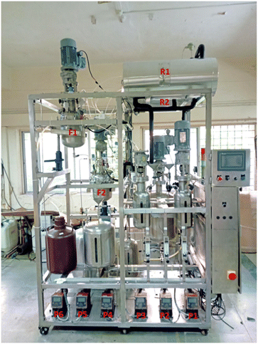
A pilot plant (with overall dimension of 1.67 m × 1.2 m × 1.98 m) was designed with a production capacity of 1 kg per day of mesoporous silica particles and contains three sections, namely the pumping section, reaction section and separation section. For the pilot-scale reactor, PTFE tubes of 1/4 inch in diameter (VICI, inner diameter = 4.75 mm, volume > 1.5 L) were used. Two individual jacketed reactors were constructed, making the tubes form a triple helical shape and jackets were connected in series for heating through a constant-temperature water circulation unit (Julabo, Germany) which provide co-current operation during the reaction. An inlet was given to the outermost helix while an outlet was taken from the innermost helix. The stronger secondary flows resulting from smaller diameter helical coils were used to drive the suspension with growing particle sizes from to the outlet. The heat losses are reduced by insulating the shell with glass wool and aluminium cladding. These two reactors made with the above tube specifications were placed to operate in parallel or in switching mode, as and when needed.The reagent was stored in storage vessels, equipped with stirrer having motors with VFD to control the speed and were pumped using diaphragm pumps (Grundfos GmbH) from the storage vessels into the nucleation section, where a tee mixer was placed in a jacketed shell. These pumps have the connectivity needed for advanced control of the process and operations through a PLC system. The flow coming out of the nucleation section was directed to the reactor to be used with the help of a solenoid valve. Only one reactor is operated at a time and during the reaction; if the pressure in the reactor exceeds a set threshold limit, the flow was switched to the second reactor. In such a situation, the first reactor is subjected to immediate washing with dilute HF through an automated control system. A control panel with a PLC system and SCADA interface on an HMI were installed for monitoring the flow rates, pressure and temperature of the heating and cooling systems. The pressure measured by the pressure transmitter (Wika, SS316) was used to decide the on/off mode for the pump and solenoid valve. The line connecting from the pump to the inlet of the reactor housed a non-return valve (Swagelok, SS316), rotameter (Eureka, 1–100 ml min−1), solenoid valve (Saad, 10 bar), and temperature (Radix, SS316) and pressure transmitters in sequence from the outlet of the pump to the inlet of the reactor.
For the separation of particles from the solution, a two-stage continuous filtration unit with mesh sizes of 500 nm and 1000 nm, respectively, was installed. The reaction mass from the outlet of the reactor enters the first filtration unit then the second filtration unit, separated using a valve provided between the two filtration units, which allows the filtrate to pass into the second filtration unit. Filtrate (supernatant) from the second unit is collected in the storage vessel provided at the bottom. Intermediate methanol wash is also given to quench the reaction and prevent the particles from further aggregation and deposition. Washed methanol was collected separately and recycled back to the first filtration unit. The supernatant can either be recycled back to the first reactor or allowed to stir for a certain time to grow the particles further. All the components in the pilot plant were skid-mounted as shown in Fig. 1. Further details on the process are not given due to confidentiality.
Results and discussion
A continuous flow reactor followed by a separation/recovery unit with a production capacity of 1 kg per day was installed. The synthesis was performed under the same conditions that we optimised for lab-scale processes. The production was scaled up by increasing the reactor volume and the tube diameter. The one-step synthesis of this material was previously performed on a 0.3 g h−1 laboratory scale using 1/8′′ tubing (5.8 meters) and then scaled up to 3 g h−1 scale, and finally designed to give 30–50 g h−1 by using 1/4′′ PTFE tubing. The objective of this study is large scale production of micron size mesoporous silica particles with a high surface area and pore diameters in the range of 2–5 nm and to operate it continuously for a sufficiently long time (>6 to 8 hours without clogging).The pilot plant was subjected to several cold flow tests before going for an actual operation at full capacity. This included checking the accuracy and performance of all electronic components and instrumentation, and obtaining an estimate of major issues that can arise while scaling-up the process (such as pump pulsation, mixing, reactor clogging, separation efficiency, etc.). For the pilot-scale operation, we used diaphragm pumps as the reciprocating action of the diaphragm generates pulsing flow that affects axial mixing, which could be overcome by applying a back pressure valve (4 bar) in line at the discharge side of the pump. In reality this pulsation in the long helical coil reactor also helped achieve almost plug flow and also facilitated movement of the particles. Proper functioning of the solenoid valve is of utmost importance as it manages the flow transition from one reactor to another based on the pressure reading obtained from the transmitter. It is absolutely essential that the solenoid valves remain functional during the reactor switching process or intermediate washing operation, as otherwise it can impede the overall operation and potentially lead to clogging of the reactor due to the inability to perform the necessary cleaning procedures. To avoid overflow from the two-stage filtration unit after a continuous run of few hours due to the formation of a layer of particles on the mesh, a vacuum pump was installed at the outlet of the first unit. Level indicators were used in both the filtration units to monitor the liquid level while following the intermediate washing protocol. Heat transfer coefficient and dispersion number were measured for the reactor. This information is expected to help in obtaining quantitative data on mixing in the reactor and its performance for scale-up.
Heat transfer coefficient
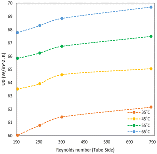
As mentioned in the reactor design section, a helical coil tubular reactor made up of PTFE 1/4′′ tubing was used for this synthesis. The reactor is provided with a jacket to maintain a constant temperature in the reactor by circulating a heating fluid through a constant-temperature bath (Julabo, Germany). Initially, the reactor was filled with water and was circulated at a low flow rate at room temperature and the utility (thermostat) was set for the appropriate reaction temperature. When the system had reached a steady state, the temperature of the fluid leaving the reactor outlets was measured. The heat transfer coefficient was calculated by considering geometrical effects like coil pitch, helix diameter, Dean number and Nusselt number. Empirical correlation proposed by Salimpour et al. was used for calculating shell and tube side heat transfer coefficients.18 From Fig. 2, it is observed that with increasing flow rate (tube side or shell side), the overall heat transfer coefficient increases. Heat transfer inside the continuous flow reactor is limited by the tube side heat transfer i.e. thermal conduction, and a high heat transfer rate can be accomplished by improved thermal conduction due to the high surface-area-to-volume ratio as well as high flow rates. For an endothermic reaction as in this case, the measured heat transfer coefficient was sufficient to achieve the desired reaction temperature.Residence time distribution
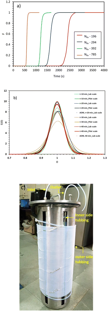
In a helical coil, centrifugal force acts normal to the flow direction due to the curvature of the reactor and induces secondary flow inside the reactor. As a result of its finite curvature, this secondary flow prevents back mixing and enhances radial mixing. The pilot-scale facility encompasses numerous joints and connections that can alter fluid flow characteristics i.e., mixing. In order to quantify the extent of deviation from the lab scale reactor, it is necessary to measure the residence time distribution for the pilot-scale reactor. Attaining nearly ideal reactor performance is crucial for achieving nanoparticles with a narrow particle size distribution. The effect of curvature ratio and flow rate on the axial dispersion has been studied well in the literature.19,20 Generally, helical coil reactors provide low variance RTD as compared to straight tubes of the same length with higher pressure drop per unit length of the reactor.21In view of this, here we have studied the residence time distribution at the pilot-scale using a step input method to investigate the effect of flow rate on the flow characteristics. Experiments were performed at different flow rates such as 44, 66, 88, and 176 ml min−1. The exit age distribution of molecules in the reactor is obtained by analysing the tracer conductivity (C(t)) at the outflow using eqn (1)22
 | (1) |
 | (2) |
 | (3) |
 | (4) |
With the assumption of a close-close boundary condition, the laminar flow of a non-viscous fluid in a long pipe and negligible radial diffusion were considered for calculating the dispersion coefficient as given in eqn (4). ‘D’ represents the axial dispersion of the tracer due to the convection and signifies the degree of deviation from the plug flow. Smaller values of D/uL < 0.01 denoted the lesser deviation from the plug flow, whereas values above 0.01 indicate more deviation from the plug flow (i.e. tending towards a mixed flow reactor).
The mathematical expression for the axial dispersion model is (eqn (5)),
 | (5) |
| Sr. no. | Reactor volume (ml) | Residence time (min) | Reynolds number NRe | Velocity (m s−1) | D/uL |
|---|---|---|---|---|---|
| 1 | 22 | 10 | 21.68 | 0.0101 | 0.0011 |
| 2 | 22 | 20 | 10.84 | 0.0051 | 0.0012 |
| 3 | 22 | 30 | 7.23 | 0.0034 | 0.0018 |
| 4 | 22 | 40 | 5.42 | 0.0025 | 0.0009 |
| 5 | 1771 | 10 | 784.93 | 0.1656 | 0.0017 |
| 6 | 1771 | 20 | 392.46 | 0.0828 | 0.0013 |
| 7 | 1771 | 30 | 294.35 | 0.0621 | 0.0012 |
| 8 | 1771 | 40 | 196.23 | 0.0414 | 0.0005 |
Fig. 3(a) illustrates F-curves and shows the distinctive characteristic of flow at different Reynolds numbers. As the fluid flow velocity increased, the curve becomes sharper, resulting in the increasing flow dispersion number. Lower values of dispersion coefficient signify the reduction in the axial dispersion within the reactor, reflecting an ideal system behaviour. However, the axial dispersion model was fitted well with experimental E(θ) curves as depicted in Fig. 3(b). The resulting dispersion numbers are less than 0.01 and signify that the 100 m long helical coil reactor with a curvature ratio of 0.1938 behaves ideally at the pilot-scale (Table 1). The time spent by the molecules inside the reactor are equal, which is confirmed by the particle size distribution of the mesoporous silica nanoparticles obtained at NRe = 392 (Fig. S1, ESI†). The minimum standard deviation (±7 nm) in particle size ensures that each particle experience an equal residence time inside the reactor. Hence, the reactor design does not exhibit dead zone or short circuiting or channelling inside to reactor, making it advantageous for achieving a narrow particle size distribution.
Pilot plant operation
MSPs are synthesised using the soft templating sol gel approach, which involves hydrolysis and condensation of tetraethyl orthosilicate (TEOS) under basic conditions in the presence of a cationic surfactant as a soft template and a water-alcohol mixture. The reactions were performed over a residence time of 16 to 35 minutes using a PTFE-based helical coil tubular reactor (>1.5 L). The reactants are fed to the reactor by using a diaphragm pump with a total flow rate of 50–110 ml min−1. Two separate stock solutions were prepared. The organic stock solution contained a mixture of TEOS (0.15–0.23 M), methanol, and TMB (0.019–0.03 M), whereas the aqueous stock contained a mixture of CTAB (0.01–0.015 M), water, NaOH (0.003–0.007 M), and methanol. The ratio of organic to aqueous solution flow rate is 0.099. In each experiment, methanol and water were used at an equal (1![[thin space (1/6-em)]](https://www.rsc.org/images/entities/char_2009.gif) :
:![[thin space (1/6-em)]](https://www.rsc.org/images/entities/char_2009.gif) 1) volumetric ratio.
1) volumetric ratio.
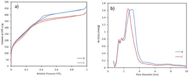
The pilot-scale reaction was carried out by using laboratory optimized conditions and an experimental procedure.23 MSPs with an average diameter of 876 ± 12 nm were produced with a BET surface area of 1052 m2 g−1 and pore size 2.4 nm. The associated plots of nitrogen adsorption–desorption isotherm and pore size distribution are shown in Fig. 4. We successfully reproduced the lab scale protocol and properties of MSPs in terms of size, yield and surface area at the pilot-scale. With this, MSPs were produced with a 32 g h−1 production rate. However, after 60 minutes of continuous running, the reactor got clogged. Further, we carried out the run at a lower NaOH concentration, so that the yield of particles would be lower and the chances of clogging would eventually be lower. But also in this case, we observed clogging after a 63-minute reaction time. This implied that we can expect our reactor to clog at some point because the synthesis of nanoparticles is prone to clogging reactors. But we never expected it to clog so soon. The blockage was intense and we had to open the tube winding. Interestingly, we noticed that in both cases, the reactor was clogged close to the initial stage of the tube at a distance of around 10–20 metres, while at the rest of the tube length, the reaction mixture was freely moving. This is attributed to the colloidal stability of particles. The growth of particles occurs when the particles are colloidally unstable; they undergo aggregation and adhesion at an early stage, which leads to particle accumulation at the reactor wall.24 Once the particles were stabilised, there were fewer chances of reactor clogging. The colloidally stable suspensions form a particle monolayer on the surface of the wall, which aids in preventing further particle deposition by blocking the particles' interactions with one another.25,26 Hence, we used different strategies to prevent the reactor from clogging, enabling us to run it longer without compromising the product's quality.
Periodic pulsation
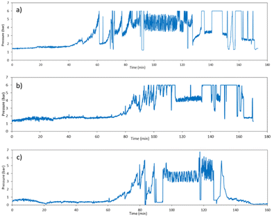
The reactor clogging was the main issue that we encountered while working on the pilot plant. Even after diluting the reactant concentration and performing the reaction at a lower temperature, the reactor clogging problem could not be solved. Hence, we used periodic intense flushing of the reactor with solvent as a strategy that can be used to prevent reactor clogging. In periodic pulsation, a pulse of solvent is given only for a few seconds either with the same flow rate (88 ml min−1) or twice the reactant flow rate, which will disturb the temporary adhesion of particles or agglomerates on the wall. A very high shear for a short time forces the particles deposited on the reactor wall to get free or break the constriction.27Fig. 5a shows the pressure profile with respect to time, where the pulse of methanol was given; when we observed, the pressure started increasing at 50 minutes. This progressive rise in pressure indicates rapid growth of obstructions or blockage in the reactor. Pulses of methanol at 88 ml min−1 flow rate for 5 s were given three times in every 10 minutes. However, after 80 minutes, pressure continuously increased even after giving the pulse, leading to clogging of the reactor. Then, we made the decision to give a pulse at the beginning of the reaction itself every 10 minutes at a flow rate of 88 ml min−1 for 5 seconds. As a result, the reactor clogging time was delayed by 20 minutes as seen in Fig. 5b. However, after 100 minutes of continuous operation, the pressure in the reactor reached 6 bar, at which point we stopped the reaction and the reactor was flushed automatically by methanol until the pressure dropped to 0.3 bar. Many experiments were performed by varying the pulse time and flow rate of methanol and the observations are reported in Table 2. Fig. S3† illustrates the pressure profile concurrent with the rise in fluid flow velocity resulting from methanol pulsation at a rate of 88 ml min−1 for a duration of 10 s occurring every 10 minutes. Increasing superficial velocity demonstrated a delay in clogging, albeit concomitantly leading to reduction in the overall residence time of the process.| Sr. no. | Nucleation temp (°C) | Growth temp (°C) | NaOH conc. (M) | Pulse time/flow rate | Clogging time (min) & cut-off pressure | Dp/SD (nm) | Yield% |
|---|---|---|---|---|---|---|---|
| A | 35 | 55 | 0.0045 | No pulse | 60 min@6 bar | 886 ± 10 | 45 |
| B | 55 | 55 | 0.0045 | 5 s@88 ml min−1 | 80 min@6 bar | 703 ± 9.5 | 49 |
| C | 45 | 45 | 0.0045 | 5 s@88 ml min−1 | 95 min@5 bar | 919 ± 13 | 38 |
| D | 35 | 65 | 0.003 | 10 s@88 ml min−1 | 90 min@5 bar | 755 ± 8.6 | 52 |
| E | 35 | 65 | 0.003 | 15 s@88 ml min−1 | 76 min@6 bar | 788 ± 11 | 43 |
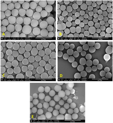
In order to do further fine tuning of the synthesis protocol, we also varied the temperature of nucleation (TN) and growth section (TG), to check its effect on particle size and distribution. When the temperature at the nucleation section was kept low (35 °C), close to micron-sized MSPs were produced with an average diameter of 919 nm (±23 nm) as seen in Fig. 6(A and C). Whereas when the reaction was carried out while keeping the temperature at 55 °C at both sections, the particle size decreased to 700 nm, and the corresponding particle size distribution is shown in Fig. S1 (ESI†). This indicated that nucleation is a fast process. At higher temperatures, burst nucleation occurs, producing more nuclei and ultimately smaller-diameter particles. For instance, the growth of the particles is often a slow process, which is difficult to complete in the residence time available in continuous systems, or we cannot give a longer residence time in a flow reactor as it would need lower flow rates and hence could lead to solid deposition and blockage problems in flow reactors. Thus, the growth rates can be accelerated while keeping a high reaction temperature in the growth section. Therefore, by adjusting the temperature in both the sections, the nucleation and growth rate can be controlled to get a higher yield as well as a larger particle size. But at the same time, with an increase in size and yield of particles, the pressure in the system will rise because larger particles have a tendency to settle (see Fig. S2 in the ESI† for settling velocity vs. particle size), which can lead to higher chances of clogging. The settling velocity of micron-sized particles is 100 times greater than that of particles 10 nm in size. If the particle settling velocity is greater than the superficial velocity of the fluid, particles will settle. During particle growth, aggregation also happens and if the particle cluster size goes beyond 200 microns, it will settle, which reduces the flow area and increases pressure drop.
Two phase segmented flow (slug flow)
In the past, we had explored the possibility of delaying clogging or avoiding fouling by using multiphase flow in a small tubular reactor (1.43 and 1.9 mm ID).28 Fouling can be avoided when the reacting medium is segmented into small batches by introducing an inert gas, which prevents the nanoparticle synthesis domain from coming into contact with the reactor wall. Gas–liquid segmentation significantly improves the mixing by creating recirculation inside each liquid segment; thus, each segment acts as a nearly independent nanoliter reactor, producing particles with a narrow size distribution.29,30 Furthermore, segmented flow can prevent the settling of larger particles, such as agglomerates, forming when nanoparticle stabilisation is incomplete during early phase of reaction.24 We supplied nitrogen as an inert gas at a 22 ml min−1 flow rate (25% of total flow rate) using a mass flow controller (Brooks Instruments, SLA5800) to the inlet of the reactor (after the tee mixer). Initially, we performed the experiments under mild experimental conditions to observe the feasibility of the process using slug flow. When a flow reactor clogs, it can be exceedingly challenging to remove the clogging and take several days to remove the clog. Hence, we decided to operate the reactor up to 3–4 bar pressure. In our previous study, we found that the NaOH concentration and temperature have the maximum impact on the yield and size of MSPs. We are actually reducing the solid content (yield) of the reaction by running it under mild conditions, which reduces the likelihood of reactor blockage. We had found that clogging time depends on all these process parameters, like temperature, concentration, and reaction time. MSPs in the micrometre size range are produced at high temperatures up to 65 °C and NaOH concentrations, as these two parameters accelerate the relative rates of hydrolysis and condensation of TEOS. As a result, the yield of particles also increased. Larger particles quickly settle or gather at the wall due to the high settling velocity, which eventually increases the system pressure. Also, with particles getting synthesized and growing, the overall density as well as viscosity of the solution increases along the reactor length, leading to pressure increase. Theoretically, depending on the % conversion of TEOS, the pressure drop with 100% conversion will be at least 5 times higher than in the absence of any particles, which would add frictional resistance to the suspension. Thus, it has been challenging to produce larger particles with a high yield without clogging the flow reactor. It is important to note that the slug length at the inlet of the reactor was 8D (where D is the tube diameter), while at the outlet is became almost 20D due to changes in the physicochemical properties of the liquid phase along the reactor length that facilitated coalescence of gas slugs.Initially, the reaction was performed at 35 °C using a 0.0045 M NaOH concentration. The flow rate of gas (22 ml min−1 N2) was kept at 25% of the total flow rate, which resulted in lower flow rates for a fixed/desired residence time. The flow rates of both the stock solutions were adjusted so that the time spent by the liquid slug would be 20 minutes. We observed that using slug flow, the reactor was continuously operated for 3 hours without any clogging issues. Fig. 7a shows that the pressure of the system reached only 0.7 bar, indicating that no significant wall deposition occurred while producing monodisperse mesoporous silica particles with an average diameter of 458 nm (SD ± 7.8), as seen in Fig. 7b. Magnified HR-TEM images clearly show that the particles are highly porous with cubic pore structures. The confirmation of mesostructural ordering was additionally substantiated through the wide-angle X-ray diffraction pattern (Fig. S4, ESI†). The particles manifested a distinct diffraction peak at 2Θ = 0.92, corresponding to the (210) plane, while relatively broad peaks emerged at 2Θ = 1.02 and 1.7, corresponding to the (211) and (400) reflections, respectively, with a cell parameter of 210.54 A°. These observations are indicative of a cubic mesophase.
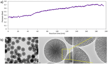 | ||
| Fig. 7 a) Pressure profile of the reaction system using slug flow 25%, and b) HR-TEM images of MSPs obtained using slug flow at 35 °C, 25% N2 flow rate, NaOH 0.0045 M. | ||
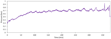
A decrease in particle size was obvious in a two-phase flow liquid (reaction mass) confined in a slug; hence, the supply of precursors for growth is limited. Further, to operate the reactor for a longer time, the reaction was performed continuously for 6 hours at 35 °C using 100% NaOH concentration (0.006 M). Initially, pressure increased from 0.3 bar to 0.7 bar, then became stable at 0.7 bar for almost 6 hours (Fig. 8). This indicates that by operating the reaction at a lower temperature, we could operate the reactor without clogging. Moreover, the yield could be further increased by collecting the material coming out of the tubular reactor in a batch reactor and allowing it to stir for 1 hour at 55 °C, which anyways happens in any collection vessel.
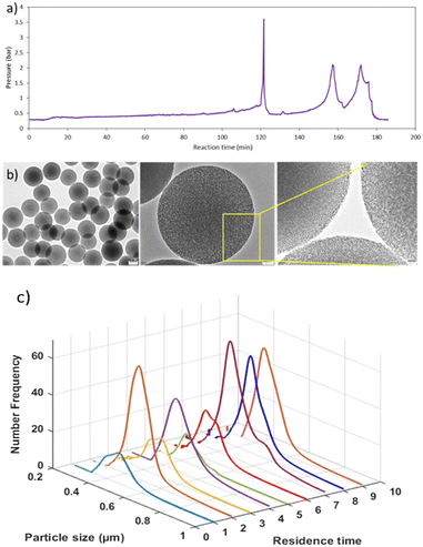
Further, the reaction was also performed by increasing the temperature of the growth section to 55 °C using 0.0045 M NaOH. In this case, the pressure started increasing after 150 minutes, and a pulse of gas was given twice to release the pressure (Fig. 9a). Using the TG at 55 °C, MSPs with average diameter of 490 nm (SD ± 7.6) were produced (Fig. 9b). Samples were collected at each RT for up to three hours to check the particle size distribution and product consistency throughout the reaction time. The distribution was broader for the first two RTs, then became narrower, as seen in Fig. 9c, which indicated that a steady state was achieved after the second RT. Not much variation in particle size and distribution was observed after that and hence it is confirmed that the product quality was consistent throughout the reaction. When the reactor was operated using laboratory optimized conditions at higher base concentration (NaOH = 0.006 M, TG 55 °C), MSPs with 866 nm (SD ± 15) were produced. With a higher temperature in the growth section, we can operate the reactor for up to 3 hours. Thus, longer operations were possible by switching the reactor after 3 to 4 hours. In this way, clogging can be avoided completely without compromising the material's properties. It is worth noting that, clogging cannot be prevented completely especially for synthesis of larger size particles, the only thing we can do is to delay it by introducing a second phase or switch the flow to a parallel reactor thereby flushing the other reactor, keeping it ready for use in a periodic manner without stopping the plant. Otherwise a mechanism to periodically flush the system in a very short time (<10 s) should be decided. To date, we have produced more than 1.5 kg of MSPs. We believe that this approach will provide guidance to enable high-yield production on a commercial scale, paving the way for the industrialization of mesoporous silica-based materials.
Conclusions
In summary, we have developed a scale up approach for continuous flow synthesis of mesoporous silica particles. The obtained silica particles have a high surface area >700 m2 g−1 and 0.4–0.7 cm3 g−1 pore volume. MSPs with a controllable diameter in the range of 400–1000 nm were produced in 20 minutes of reaction time, enabling a production rate of 20–50 g h−1. The hydrodynamic study was carried out on both the laboratory and pilot-scale reactor, and the results showed that they had a similar nature of residence time distribution. This similarity is a key parameter that ensures that the necessary yield and uniformity in particle size distribution can be achieved. Different strategies were used to prevent reactor clogging. The first strategy was the dilution of the reaction mixture by keeping a lower concentration of base and the reaction temperature, but it did not help to prevent the reactor from clogging due to higher settling velocities and the boundary layer stagnancy. The second strategy involves giving a periodic pulse of methanol, whereas in third strategy we used two phase flow (slug flow). We could not prevent the clogging completely with this periodic pulsation; only the reactor clogging time was delayed by 20–30 minutes. The reactor was operated continuously for 6 hours in a clogging-free manner when N2 was introduced as an inert phase. This two-phase flow proved helpful for obtaining a narrow particle size distribution as well as preventing the reactor from clogging. Although clogging cannot be totally avoided, it can be managed by switching the flow to a parallel reactor and operating the plant in a periodic manner without entirely stopping it down. The pressure recordings obtained during the two-phase flow, as well as the clogging studies performed subsequent to the experiments, showed no sign of reactor clogging, demonstrating the suitability of the reactor design for long-term operation and commercial-scale production.Abbreviations
| CTAB | Cetyltrimethylammoniumbromide |
| MRI | Magnetic resonance imaging |
| NaOH | Sodium hydroxide |
| TEOS | Tetraethylorthosilicate |
| PLC | Programmable logic controller |
| SD | Standard deviation |
| TMB | Trimethylbenzene |
| PTFE | Polytetrafluoroethylene |
| VFD | Variable frequency drive |
| RT | Residence time |
| RTD | Residence time distribution |
Author contributions
RBJ developed the process, performed the experiments, analysed the data, and wrote the manuscript. JRS performed the experiments, helped in the interpretation of results at various stages of development, and edited the manuscript. AAK was involved in conceptualization of the experiments and editing of the manuscript. HKJ helped in conducting experiments, material separation, and recovery. HSD helped in conducting HTC and RTD experiments. AVP was involved in the design and fabrication of the pilot plant. All authors have given their approval to the final version of the manuscript.Conflicts of interest
The authors have filed a patent on this process.Acknowledgements
R. Jundale acknowledges CSIR-HRDG for senior research fellowship. JRS acknowledges the CSIR, India for the CSIR-GATE fellowship. The authors would like to thank Dr. Nilesh Mali (Scientist, CSIR-NCL, Pune) for providing a MFC for conducting experiments. RJ and JRS would like to thank Ms. Srivarshini RK for her assistance in the sample preparation. The authors acknowledge the funding from the Dept. of Science and Technology (GoI)'s Advanced Manufacturing Technologies (AMT) scheme (DST/AMT/TSG/2015/380) and CSIR-First project (MLP102726).References
- A. Mehmood, H. Ghafar, S. Yaqoob, U. F. Gohar and B. Ahmad, J. Dev. Drugs, 2017, 6, 174 CrossRef.
- S.-H. Wu, Y. Hung and C.-Y. Mou, Chem. Commun., 2011, 47, 9972–9985 RSC.
- J. L. Vivero-Escoto, I. I. Slowing, B. G. Trewyn and V. S. Y. Lin, Small, 2010, 6, 1952–1967 CrossRef CAS PubMed.
- F. Tang, L. Li and D. Chen, Adv. Mater., 2012, 24, 1504–1534 CrossRef CAS PubMed.
- P. Yang, S. Gai and J. Lin, Chem. Soc. Rev., 2012, 41, 3679–3698 RSC.
- J. Liu, T. Liu, J. Pan, S. Liu and G. Lu, Annu. Rev. Chem. Biomol. Eng., 2018, 9, 389–411 CrossRef CAS PubMed.
- I. I. Slowing, B. G. Trewyn, S. Giri and V. Y. Lin, Adv. Funct. Mater., 2007, 17, 1225–1236 CrossRef CAS.
- Y. Ma, L. Qi, J. Ma, Y. Wu, O. Liu and H. Cheng, Colloids Surf., A, 2003, 229, 1–8 CrossRef CAS.
- B. J. Melde, B. J. Johnson and P. T. Charles, Sensors, 2008, 8, 5202–5228 CrossRef CAS PubMed.
- H. C. Wang, C. Lu, H. Bai, J. F. Hwang, H. H. Lee, W. Chen, Y. Kang, S.-T. Chen, F. Su and S.-C. Kuo, Appl. Surf. Sci., 2012, 258, 6943–6951 CrossRef CAS.
- Y. Liu, Y. Yao, J. Fu, W. Hu, J. Feng, J. Wan and C. Yu, Microporous Mesoporous Mater., 2021, 316, 110976 CrossRef CAS.
- K. Zhang, L.-L. Xu, J.-G. Jiang, N. Calin, K.-F. Lam, S.-J. Zhang, H.-H. Wu, G.-D. Wu, B. Albela and L. Bonneviot, J. Am. Chem. Soc., 2013, 135, 2427–2430 CrossRef CAS PubMed.
- V. Sebastian, S. A. Khan and A. A. Kulkarni, J. Flow Chem., 2017, 7, 96–105 CrossRef CAS.
- A. H. Bari, R. B. Jundale and A. A. Kulkarni, Chem. Eng. J., 2020, 398, 125427 CrossRef CAS.
- R. Jundale, A. Bari, C. Thara and A. Kulkarni, J. Flow Chem., 2018, 8, 59–67 CrossRef.
- Z. Yi, L. F. Dumée, C. J. Garvey, C. Feng, F. She, J. E. Rookes, S. Mudie, D. M. Cahill and L. Kong, Langmuir, 2015, 31, 8478–8487 CrossRef CAS PubMed.
- V. Sebastian, M. Arruebo and J. Santamaria, Small, 2014, 10, 835–853 CrossRef CAS PubMed.
- M. R. Salimpour, Exp. Therm. Fluid Sci., 2009, 33, 203–207 CrossRef CAS.
- R. Trivedi and K. Vasudeva, Chem. Eng. Sci., 1975, 30, 317–325 CrossRef CAS.
- C. G. Slominski, W. D. Seider, S. W. Churchill and J. Seader, Ind. Eng. Chem. Res., 2011, 50, 8842–8850 CrossRef CAS.
- M. D. Johnson, S. A. May, J. R. Calvin, J. Remacle, J. R. Stout, W. D. Diseroad, N. Zaborenko, B. D. Haeberle, W.-M. Sun and M. T. Miller, Org. Process Res. Dev., 2012, 16, 1017–1038 CrossRef CAS.
- A. D. Martin, Chem. Eng. Sci., 2000, 55(23), 5907–5917 CrossRef CAS.
- R. B. Jundale, B. L. Prasad, R. N. Devi and A. A. Kulkarni, Ind. Eng. Chem. Res., 2024, 63(4), 1843–1852 CrossRef CAS.
- M. O. Besenhard, S. Pal, G. Gkogkos and A. Gavriilidis, React. Chem. Eng., 2023, 8, 955–977 RSC.
- J. L. Perry and S. G. Kandlikar, Microfluid. Nanofluid., 2008, 5, 357–371 CrossRef.
- S. Yiantsios and A. Karabelas, Int. J. Multiphase Flow, 1998, 24, 283–293 CrossRef CAS.
- J. Wagner and J. Köhler, Nano Lett., 2005, 5, 685–691 CrossRef CAS PubMed.
- S. Pal and A. A. Kulkarni, Chem. Eng. Sci., 2019, 199, 88–99 CrossRef CAS.
- S. Marre and K. F. Jensen, Chem. Soc. Rev., 2010, 39, 1183–1202 RSC.
- S. A. Khan, A. Günther, M. A. Schmidt and K. F. Jensen, Langmuir, 2004, 20, 8604–8611 CrossRef CAS PubMed.
Footnotes |
| † Electronic supplementary information (ESI) available. See DOI: https://doi.org/10.1039/d3re00707c |
| ‡ RBJ and JRS equal contributions to this work. |
| This journal is © The Royal Society of Chemistry 2024 |

