 Open Access Article
Highly efficient circularly polarized electroluminescence based on chiral manganese(II) complexes†
De-Hao
Kong
a,
Yue
Wu
d,
Cui-Mi
Shi
ac,
Hao
Zeng
ac,
Liang-Jin
Xu
 *abc and
Zhong-Ning
Chen
 *abc
*abc
aState Key Laboratory of Structural Chemistry, Fujian Institute of Research on the Structure of Matter, Chinese Academy of Sciences, Fuzhou 350002, China. E-mail: xuliangjin@fjirsm.ac.cn; czn@fjirsm.ac.cn
bFujian Science & Technology Innovation Laboratory for Optoelectronic Information of China, Fuzhou 350108, China
cUniversity of Chinese Academy of Sciences, Beijing, 100039, China
dSchool of Chemistry and Chemical Engineering, Liaocheng University, Liaocheng, Shandong 252000, China
First published on 18th September 2024
Abstract
Currently reported circularly polarized luminescent devices are primarily based on rare earth and noble metal complexes or lead perovskite materials. Reports on electroluminescent devices employing eco-friendly luminescent materials are notably scarce. In this study, we strategically designed and synthesized manganese complexes featuring Binapo as the chiral ligand. The complex structure reveals a tetrahedral coordination configuration, with the R/S configurations exhibiting a mirror relationship. Leveraging the strong ligand field and chiral structural characteristics of Binapo, the enantiomers display red emission and exhibit significant circularly polarized luminescence with a circularly polarized luminescence asymmetric factor (glum) of 5.1 × 10⁻³. The circularly polarized electroluminescent performance was investigated by using a solution processing method and host–guest doping strategy. Our efforts resulted in device performance with an external quantum efficiency (EQE) exceeding 4%, and its electroluminescent asymmetric factor (gEL) reached an impressive −8.5 × 10⁻³. This surpasses the performance of most devices relying on platinum (Pt) and iridium (Ir) metal complexes and perovskite related materials. Our work establishes a pathway for the development of cost-effective and environmentally friendly chiral electroluminescent materials and devices.
Introduction
Circularly polarized electroluminescence (CPEL) has garnered increasing attention due to its efficient generation of circularly polarized light and its wide range of potential applications in areas such as three-dimensional (3D) displays, optical communication for spintronics, and optical data storage.1 Progress in the field of chiral luminescent materials and efficient CPEL has been made since the pioneering work of Meijer et al. in 1997 when the first CPEL device was developed.2 The most widely used chiral emitters include chiral fluorescent materials,3 chiral phosphorescent materials,4 and chiral rare-earth complexes.5 However, these materials are often plagued by issues such as low device efficiency or high costs due to limited raw material availability. Recently, circularly polarized thermally activated delayed fluorescence (CPTADF) materials have emerged as promising candidates for achieving efficient CPEL,6 thanks to their ability to fully utilize excitons through reverse intersystem crossing processes. Nevertheless, the development of such chiral materials demands intricate structural design and labor-intensive synthesis routes. Chiral perovskite-based materials also show potential for efficient CPEL;7 however, concerns regarding stability and lead toxicity may hinder their commercial viability. Therefore, developing cost-effective and eco-friendly chiral emitters that can achieve highly efficient CPEL is still desirable and urgent.Eco-friendly manganese(II)-based complexes and hybrids have been extensively explored for various applications, owing to their affordability, ease of preparation, and excellent photophysical properties.8 For example, Xiong et al. reported a series of ferroelectric materials with impressive performance by employing red-emissive Mn(II) hybrids.9 Ma and Xia et al. demonstrated green-emissive Mn(II) hybrids capable of scintillation.10 Mn(II) phosphors with thermochromic and vapochromic properties hold promise for anti-counterfeiting applications.11 Furthermore, highly efficient organic light-emitting diodes have been developed using Mn(II) hybrids and complexes with strong emission.12 The introduction of chiral organic ligands into emissive Mn(II) motifs has enabled the realization of circularly polarized luminescence.13 To the best of our knowledge, no documented efforts have been made to achieve electroluminescence utilizing chiral manganese(II) emitters.
Here, we have successfully synthesized chiral manganese complexes, R/S-Mn(Binapo)Br2, with a four-coordinate configuration using chiral R/S-Binapo and MnBr2. Structural analysis reveals that the enantiomers exhibit mirror-symmetric structures. CD spectra also indicate chiroptical properties that are distinct from those of the phosphine ligand. Despite the four-coordinate configuration, we observed significant red emission, possibly due to the strong coordinating field of oxygen. Subsequently, we investigated their circularly polarized properties in the excited state and found a high glum of approximately 5.1 × 10⁻³. Based on the excellent solubility of such materials, we attempted to fabricate circularly polarized electroluminescent (CPEL) devices for the first time using a solution process and host–guest doping strategy, achieving an external quantum efficiency (EQE) of up to 4.1%. Surprisingly, we obtained highly efficient circularly polarized electroluminescence with a gEL of −8.5 × 10⁻³ along with good repeatability and stability, comparable or even superior to those of Pt and Ir complexes reported to date. Our work opens new avenues for the cost-effective production of circularly polarized electroluminescence.
Results and discussion
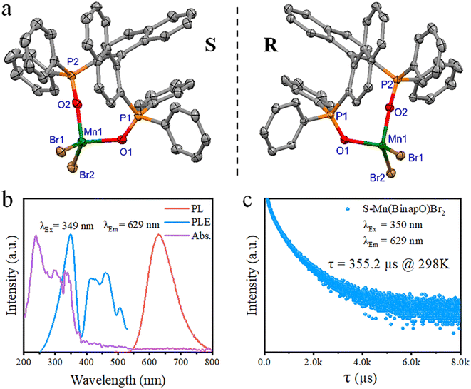
Starting with R/S-2,2′-bis(diphenylphosphino)-1,1′-binaphthyl (R/S-Binap), oxidation yielded R/S-2,2′-bis(diphenylphosphinoyl)-1,1′-binaphthyl (R/S-Binapo), which was then mixed with MnBr2 in a mixed solvent of C2H5OH and CH2Cl2 (Scheme S1 and Fig. S1–S4†). Thereafter, manganese complexes R/S-Mn(Binapo)Br2 were obtained through a solvent-diffusion method at room temperature. Through the testing of the 31P NMR spectrum of the chiral complex, we observed a significant shift in the phosphorus peak (Fig. S5 and S6†), indicating the coordination of the ligand's P![[double bond, length as m-dash]](https://www.rsc.org/images/entities/char_e001.gif) O group with Mn in the complex. The crystal structure is depicted in Fig. 1a, which crystalized in the space group of P212121. The crystal structure of the complex shows a distorted tetrahedral structure with Mn(II) ions coordinated to two oxygen atoms of the ligand (R/S-Binapo) and two bromine ions. The molecular configuration of the R-Mn(Binapo)Br2 complex is similar to the S-Mn(Binapo)Br2 complex but exhibits a mirror-symmetric configuration. The Mn–O bond lengths vary between 2.044(3) and 2.058(5) Å, Mn–Br bond lengths range from 2.468(1) to 2.4710(7) Å, and the bond angles formed by the four coordinating atoms with Mn(II) range from 94.9(1) to 122.78(6)° for the enantiomers. The details of crystal data are listed in Tables S1 and S2.† The powder X-ray diffraction (PXRD) pattern of the chiral complex R/S-Mn(Binapo)Br2 is in good agreement with the simulated results from X-ray crystallography (Fig. S7†), indicating high phase purity of the prepared complexes. Elemental mapping analysis in Fig. S8† shows a uniform distribution of manganese (Mn), bromine (Br), phosphorus (P) and oxygen (O) in the R/S-Mn(Binapo)Br2 complex. Thermal analysis reveals high thermal stability with a decomposition temperature of 450 °C (Fig. S9†).
O group with Mn in the complex. The crystal structure is depicted in Fig. 1a, which crystalized in the space group of P212121. The crystal structure of the complex shows a distorted tetrahedral structure with Mn(II) ions coordinated to two oxygen atoms of the ligand (R/S-Binapo) and two bromine ions. The molecular configuration of the R-Mn(Binapo)Br2 complex is similar to the S-Mn(Binapo)Br2 complex but exhibits a mirror-symmetric configuration. The Mn–O bond lengths vary between 2.044(3) and 2.058(5) Å, Mn–Br bond lengths range from 2.468(1) to 2.4710(7) Å, and the bond angles formed by the four coordinating atoms with Mn(II) range from 94.9(1) to 122.78(6)° for the enantiomers. The details of crystal data are listed in Tables S1 and S2.† The powder X-ray diffraction (PXRD) pattern of the chiral complex R/S-Mn(Binapo)Br2 is in good agreement with the simulated results from X-ray crystallography (Fig. S7†), indicating high phase purity of the prepared complexes. Elemental mapping analysis in Fig. S8† shows a uniform distribution of manganese (Mn), bromine (Br), phosphorus (P) and oxygen (O) in the R/S-Mn(Binapo)Br2 complex. Thermal analysis reveals high thermal stability with a decomposition temperature of 450 °C (Fig. S9†).
As shown in Fig. 1b and S10,† the solid-state reflectance spectra of R/S-Mn(Binapo)Br2 show significant absorption in the high-energy range around 200–400 nm, originating from the absorption of Binapo (Fig. S11†), attributed to n → π* and π → π* electronic transitions within the ligand. Weak absorption in the lower energy range from 350 to 600 nm likely arises from the forbidden d–d transitions of Mn2+. Upon excitation at around 350 nm, the enantiomers emit orange-red light with peaks at 633 nm and 629 nm. They exhibit lifetimes of 420 μs and 355 μs (Fig. 1c), along with photoluminescence quantum yields (PLQY) of 2.1% and 4.0% for R-Mn(Binapo)Br2 and S-Mn(Binapo)Br2, respectively (Fig. 1c, S12 and S13†). The significant Stokes shift and sub-millisecond emission lifetimes indicate that the emission originates from Mn(II) d–d transitions. Significantly, the majority of tetracoordinated Mn complexes emit green light,10a,12a,14 whereas the enantiomers we synthesized emit red light. It is well known that the luminescence mechanism of manganese is primarily due to d–d transitions, and Mn–Mn coupling can also influence its luminescence. Additionally, some recent studies have reported luminescence mechanisms involving self-trapped states. We analyzed all three possible mechanisms and found that the Mn–Mn distance in our structure (8.6 Å) far exceeds the coupling distance (∼6 Å), which rules out Mn–Mn coupling as a source of luminescence. Furthermore, based on the excited-state lifetime, we can also exclude self-trapped exciton emission. Then the Racah parameter (B) and crystal field (Dq) were calculated to evaluate the effect of the crystal field by using the Tanabe–Sugano energy level diagram (see the details in the ESI†), which give a B and Dq of 835.6 cm−1 and 1059.2 cm−1, respectively, and a ratio of Dq to B of 1.27, thus indicating a strong crystal field of Mn2+.15 Therefore, the red emission is mainly attributable to the robust crystal field from phosphine oxide. The emission spectra recorded at different excitation wavelengths in the range of 260 to 360 nm show a maximum emission wavelength around 633 nm for R-Mn(Binapo)Br2, with only a single emission center as shown in Fig. S14.† The temperature-dependent emission spectra of R-Mn(Binapo)Br2 in Fig. S15† demonstrate that as the temperature gradually decreases, the relative intensity of the emission peak increases. Importantly, there is still only one emission center, indicating that the emission solely originates from the Mn luminescent center.
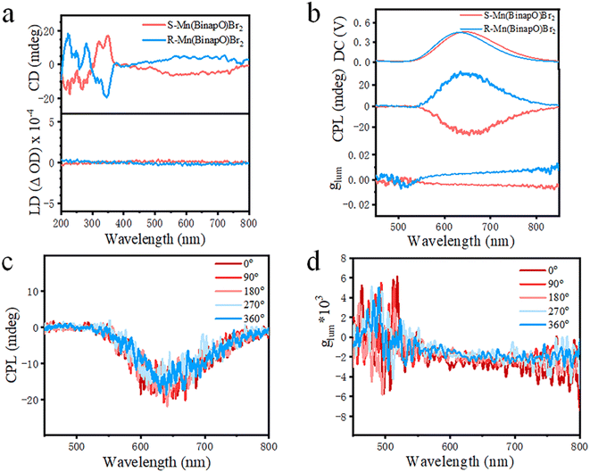
Given its chiral structural features, we explored its chiroptical properties in the ground state. As shown in Fig. 2a, the enantiomers exhibit mirror-image absorption peaks in their circular dichroism (CD) spectra. Compared to the CD spectra of the ligand (Fig. S16†), the CD signal in the range of 350 to 600 nm in the complexes is attributed to Mn d–d transitions, indicating the effective transmission of chirality from the ligand to the complexes.16 Moreover, we acquired linear dichroism (LD) spectra and nearly negligible signals were observed, thus eliminating the influence of LD. Thereafter, we explored its circularly polarized properties in the excited state and observed excellent CPL signals in the range of 550–800 nm under the bias of 0.4 to 0.5 V (Fig. 2b). In detail, we observed nearly symmetric CPL signals with the R-Mn(Binapo)Br2 complex exhibiting a positive peak and the S-Mn(Binapo)Br2 complex displaying a negative signal. The CPL signal wavelengths closely match their photoluminescence emission, confirming the chiroptical properties of these enantiomers in the excited state. To better evaluate their circular polarization performance, the photoluminescent dissymmetry factor (glum) was introduced and calculated using eqn (1) (where IL and IR represent the emission intensities for left and right circular polarization, respectively). The calculation results indicate that the glum values for R- and S-Mn(Binapo)Br2 complexes at their maximum emission wavelengths are 5.1 × 10⁻³ and −4.2 × 10⁻³, respectively.
| glum = 2 × (IL − IR)/(IL + IR) | (1) |
To eliminate the influence of linearly polarized luminescence (LPL), we measured the circularly polarized luminescence (CPL) characteristics at different angles by rotating the sample. As shown in Fig. 2c, d and S17,† during the rotating process at 0°, 90°, 180°, 270°, and 360°, the intensity and orientation of circularly polarized luminescence remained almost unchanged, indicating that the polarized emission indeed originates from CPL rather than LPL.
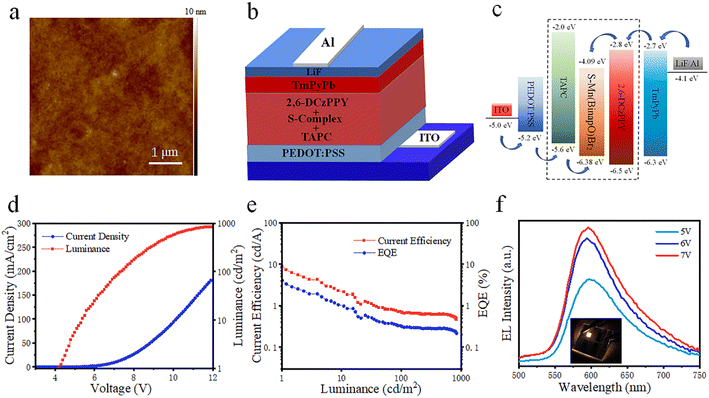
Notably, the complex exhibits improved luminescence efficiency in doped film states with a PLQY of 11.4% (Fig. S18†) due to the increased energy transfer efficiency from hosts and decreased phosphorescence quenching between guests. The emission of the doped film exhibited a blue shift, and as the proportion of the host material increased, the emission of the film gradually shifted further blue (Fig. S19†). Inspired by the high luminescence efficiency and good solubility, we fabricated electroluminescent devices using a solution process. The device structure is as follows: ITO/PEDOT:PSS/poly-TPD/S-Mn(Binapo)Br2/BmPyPb/LiF/Al. ITO and LiF/Al serve as the anode and cathode, while PEDOT:PSS and TmPyPb function as the hole-injection and electron-transport layers, respectively. OLED devices with the S-Mn(Binapo)Br2 complex as the emissive layer exhibit a maximum brightness of 31 cd m−2, current efficiency (CE) of 0.045 cd A−1, and EQE of 0.029%, as listed in Table S3.† The poor morphology of the film as shown in Fig. S20† and imperfect exciton recombination in the emissive layer in non-doped OLEDs likely result in inferior device performance. To improve charge carrier transport and film quality, we introduced doped emissive layers into the OLEDs, selecting TAPC: 2,6-DCzPPY as the doping host material. The introduction of mixed-hole and electron transport materials into the emissive layer not only promotes charge carrier balance, but also enhances the morphology of the film, as shown in Fig. 3a and S21,† resulting in improved device performance. In comparison to non-doped OLEDs, the doped device with a structure of ITO/PEDOT:PSS(50 nm)/3% wt S-complex: 32.33% TAPC: 64.67% 2,6-DCzPPy (30 nm)/BmPyPb (50 nm)/LiF (1 nm)/Al (100 nm) achieves a higher brightness, CE, and EQE of 1145 cd m−2, 4.85 cd A−1, and 2.11%. However, the turn-on voltage is as high as 6.0 V. Then we replaced the electron-transporting material BmPyPb with TPBi and TmPyPb, respectively. It was found that replacing BmPyPb with TPBi resulted in a significant decrease in device performance. Although the maximum brightness increased to 2012 cd m−2, the maximum CE, power efficiency (PE), EQE, and turn-on voltage all decreased (Table S3†), mainly due to the high energy barrier between the hole injection layer and the emissive layer in the device structure. Substituting TmPyPb for BmPyPb as the electron transport material, the orange-emitting device (Fig. 3b and c) exhibited a maximum brightness of only 843 cd m−2. The device structure and energy level diagram of the optimized OLED device are shown in Fig. 3b, c and S22.† However, the highest CE, PE, EQE, and turn-on voltage in Fig. 3d and e all showed a noticeable improvement with a current efficiency of 8.79 cd A−1 and an EQE of 4.09%, respectively. And the electroluminescent spectra located at around 600 nm as shown in Fig. 3f exhibit a blue shift compared to its photoluminescence, which is common in complex electroluminescent devices.17 Employing the optimized device structure, we substituted the S-Mn(Binapo)Br2 complex with the R-Mn(Binapo)Br2 complex and obtained a similar device performance, as shown in Fig. S23.†
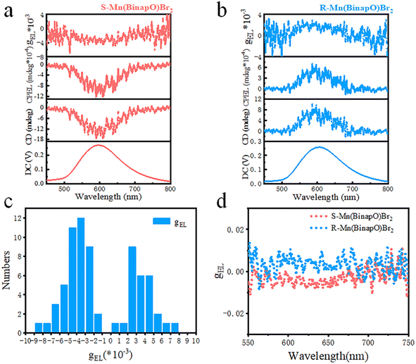
Given the excellent CPL performance of the solid-state R/S-Mn(Binapo)Br2 complexes, we conducted an in-depth study of the CPEL performance of OLED devices based on R/S-Mn(Binapo)Br2. The CPEL spectra of these OLED devices in Fig. 4a and b exhibited emission peaks at 597 and 603 nm, showing good agreement with the electroluminescence spectra. Similarly, we introduced the electroluminescence dissymmetry factors gEL to evaluate their circular polarization characteristics. Through numerous repeated measurements as shown in Fig. 4c, we obtained an average gEL value ranging from 3 × 10⁻³ to 4 × 10⁻³, demonstrating high reliability and good repeatability for this CPEL. The highest gEL values obtained in Fig. 4d for S/R-Mn(Binapo)Br2 are −8.5 × 10⁻³ and 7.6 × 10⁻³, respectively. These results surpass those of most of the reported Pt and Ir complexes and perovskite materials (Table S4†).
Conclusions
In summary, we successfully synthesized chiral manganese complexes, R/S-Mn(Binapo)Br2, using a chiral phosphine ligand, which emit orange emission due to the d–d transition of Mn(II) under strong a crystal field. The introduction of the chiral ligand endows the material with chiroptical properties, resulting in a high CD and CPL signal in ground and excited states, respectively. Furthermore, we explored their circularly polarized electroluminescence by employing a host–guest doping device, which achieved an EQE of over 4% and a maximum gEL of −8.5 × 10⁻³. All in all, we developed a CPEL device with superior circular polarization performance by employing low cost and environmentally friendly chiral Mn(II) complexes. Our work paves a promising way for constructing environmentally friendly and cost-effective OLEDs with excellent CPEL performance.Data availability
The data that support the findings of this study are available from the corresponding author upon reasonable request.Author contributions
De-Hao Kong and Hao Zeng synthesized the emitters and fabricated and characterized the OLED devices. Yue Wu and Cui-Mi Shi characterized the photophysical properties. Liang-Jin Xu provided guidance on synthesis, photophysical characterization and device fabrication. Liang-Jin Xu and De-Hao Kong wrote the manuscript. Zhong-Ning Chen supervised and directed this study.Conflicts of interest
There are no conflicts to declare.Acknowledgements
This work was supported by the National Natural Science Foundation of China (Grants 22175181, 92061202 and U22A20387) and the Fujian Science and Technology Project (Grant 2020L3022).References
- (a) J. Zhao, T. Zhang, X.-Y. Dong, M.-E. Sun, C. Zhang, X. Li, Y. S. Zhao and S.-Q. Zang, J. Am. Chem. Soc., 2019, 141, 15755 CrossRef CAS PubMed; (b) M.-M. Zhang, K.-K. Gao, X.-Y. Dong, Y. Si, T. Jia, Z. Han, S.-Q. Zang and T. C. W. Mak, J. Am. Chem. Soc., 2023, 145, 22310 CrossRef CAS PubMed; (c) D.-W. Zhang, J.-M. Teng, Y.-F. Wang, X.-N. Han, M. Li and C.-F. Chen, Mater. Horiz., 2021, 8, 3417 RSC; (d) Y. F. Wang, M. Li, J. M. Teng, H. Y. Zhou and C. F. Chen, Adv. Funct. Mater., 2021, 31, 2106418 CrossRef CAS.
- E. Peeters, M. P. T. Christiaans, R. A. J. Janssen, H. F. M. Schoo, H. P. J. M. Dekkers and E. W. Meijer, J. Am. Chem. Soc., 1997, 119, 9909 CrossRef CAS.
- (a) M. Li, Y.-F. Wang, D.-W. Zhang, D. Zhang, Z.-Q. Hu, L. Duan and C.-F. Chen, Sci. China Mater., 2020, 64, 899 CrossRef; (b) M. Li, M.-Y. Wang, Y.-F. Wang, L. Feng and C.-F. Chen, Angew. Chem., Int. Ed., 2021, 60, 20728 CrossRef CAS PubMed.
- (a) Y.-P. Zhang and Y.-X. Zheng, Dalton Trans., 2022, 51, 9966 RSC; (b) Z.-L. Gong, X. Zhu, Z. Zhou, S.-W. Zhang, D. Yang, B. Zhao, Y.-P. Zhang, J. Deng, Y. Cheng, Y.-X. Zheng, S.-Q. Zang, H. Kuang, P. Duan, M. Yuan, C.-F. Chen, Y. S. Zhao, Y.-W. Zhong, B. Z. Tang and M. Liu, Sci. China: Chem., 2021, 64, 2060 CrossRef CAS; (c) H. Gao and X. Ma, Aggregate, 2021, 2, e116 CrossRef.
- (a) F. Zinna, U. Giovanella and L. D. Bari, Adv. Mater., 2015, 27, 1791 CrossRef CAS; (b) Z. Xia and A. Meijerink, Chem. Soc. Rev., 2016, 46, 275 RSC.
- Y. Yang, N. Li, J. Miao, X. Cao, A. Ying, K. Pan, X. Lv, F. Ni, Z. Huang, S. Gong and C. Yang, Angew. Chem., Int. Ed., 2022, 134, e202202227 CrossRef.
- (a) C. Ye, J. Jiang, S. Zou, W. Mi and Y. Xiao, J. Am. Chem. Soc., 2022, 144, 9707 CrossRef CAS PubMed; (b) C.-H. Yang, S.-B. Xiao, H. Xiao, L.-J. Xu and Z.-N. Chen, ACS Nano, 2023, 17, 7830 CrossRef CAS PubMed.
- (a) Y.-H. Liu, X. Yan, L. Xiao, W. Jiang, Q. Liu, T.-C. Liu, T.-Y. Yan, C.-Y. Yue and X.-W. Lei, Adv. Opt. Mater., 2023, 11, 2301010 CrossRef CAS; (b) H. Peng, T. Huang, B. Zou, Y. Tian, X. Wang, Y. Guo, T. Dong, Z. Yu, C. Ding, F. Yang and J. Wang, Nano Energy, 2021, 87, 106166 CrossRef CAS; (c) D. Kumar Das, R. Bakthavatsalam, V. Anilkumar, B. P. Mali, M. S. Ahmed, S. S. K. Raavi, R. Pallepogu and J. Kundu, Inorg. Chem., 2022, 61, 5363 CrossRef CAS PubMed.
- (a) W.-Q. Liao, Y.-Y. Tang, P.-F. Li, Y.-M. You and R.-G. Xiong, J. Am. Chem. Soc., 2017, 139, 18071 CrossRef CAS PubMed; (b) Y. Ai, X.-G. Chen, P.-P. Shi, Y.-Y. Tang, P.-F. Li, W.-Q. Liao and R.-G. Xiong, J. Am. Chem. Soc., 2019, 141, 4474 CrossRef CAS PubMed; (c) Z. Wei, W.-Q. Liao, Y.-Y. Tang, P.-F. Li, P.-P. Shi, H. Cai and R.-G. Xiong, J. Am. Chem. Soc., 2018, 140, 8110 CrossRef CAS PubMed.
- (a) L.-J. Xu, X. Lin, Q. He, M. Worku and B. Ma, Nat. Commun., 2020, 11, 4329 CrossRef CAS PubMed; (b) M. Li and Z. Xia, Chem. Soc. Rev., 2021, 50, 2626 RSC; (c) J. Jiance, H. Kai, H. Yakun and X. Zhiguo, Adv. Opt. Mater., 2023, 11, 2300330 CrossRef; (d) B. Li, Y. Xu, X. Zhang, K. Han, J. Jin and Z. Xia, Adv. Opt. Mater., 2022, 10, 2102793 CrossRef CAS.
- (a) T. Chang, Y. Dai, Q. Wei, X. Xu, S. Cao, B. Zou, Q. Zhang and R. Zeng, ACS Appl. Mater. Interfaces, 2023, 15, 5487 CrossRef CAS; (b) H. Zi-Lin, W. Jun-Hua, L. Jian-Bin, Z. Zhi-Zhong and K. Dai-Bin, J. Mater. Chem. C, 2022, 11, 1251 Search PubMed; (c) Y. Liu, G. Liu, Y. Wu, W. Cai, Y. Wang, S. Zhang, H. Zeng and X. Li, Adv. Mater., 2023, 35, 2301914 CrossRef CAS PubMed; (d) Y. Wang, T. Cao, Z. Xu, L. Ye, Y. Gao and X. Zhuang, Opt. Mater., 2023, 143, 114160 CrossRef CAS.
- (a) L.-J. Xu, C.-Z. Sun, H. Xiao, Y. Wu and Z.-N. Chen, Adv. Mater., 2016, 29, 1605739 CrossRef; (b) S. Vijaya Gopalan, J. Atanu, C. Seong Chan, L. Sang Uck, C. Sangeun, S. Jung Inn and I. Hyunsik, Chem. Eng. J., 2023, 474, 145936 CrossRef; (c) Y. Qin, P. Tao, L. Gao, P. She, S. Liu, X. Li, F. Li, H. Wang, Q. Zhao, Y. Miao and W. Huang, Adv. Opt. Mater., 2018, 7, 1801160 CrossRef.
- (a) H.-L. Xuan, Y.-F. Sang, L.-J. Xu, D.-S. Zheng, C.-M. Shi and Z.-N. Chen, Chem.–Eur. J., 2022, 28, e202201299 CrossRef CAS; (b) J.-X. Gao, W.-Y. Zhang, Z.-G. Wu, Y.-X. Zheng and D.-W. Fu, J. Am. Chem. Soc., 2020, 142, 4756 CrossRef CAS.
- S. B. Xiao, X. Zhang, X. Mao, H. J. Yang, Z. N. Chen and L. J. Xu, Adv. Funct. Mater., 2024, 2404003 CrossRef.
- (a) S. Yan, K. Tang, Y. Lin, Y. Ren, W. Tian, H. Chen, T. Lin, L. Qiu, X. Pan and W. Wang, ACS Energy Lett., 2021, 6, 1901 CrossRef CAS; (b) Z. Zhou, T. Jiang, Y. Yang, Y. Deng, M. Wang, Y. Ma, S. Liu and Q. Zhao, Adv. Opt. Mater., 2023, 12, 2302185 CrossRef; (c) B. Su, G. Zhou, J. Huang, E. Song, A. Nag and Z. Xia, Laser Photonics Rev., 2021, 15, 2000334 CrossRef CAS.
- D. Li, X. Liu, W. Wu, Y. Peng, S. Zhao, L. Li, M. Hong and J. Luo, Angew. Chem., Int. Ed., 2021, 60, 8415 CrossRef CAS.
- (a) S. Yan, W. Tian, H. Chen, K. Tang, T. Lin, G. Zhong, L. Qiu, X. Pan and W. Wang, Adv. Funct. Mater., 2021, 31, 2100855 CrossRef CAS; (b) Y.-P. Li, X.-X. Fan, Y. Wu, X.-C. Zeng, J.-Y. Wang, Q.-H. Wei and Z.-N. Chen, J. Mater. Chem. C, 2017, 5, 3072 RSC.
Footnote |
| † Electronic supplementary information (ESI) available: Details of the experimental materials and characterization procedures, tables and figures providing additional structural and photophysical data and device performance. CCDC 2312367 and 2312368 contain the X-ray crystallographic files in CIF format for the determination of the structures of compounds. For ESI and crystallographic data in CIF or other electronic format see DOI: https://doi.org/10.1039/d4sc04748f |
| This journal is © The Royal Society of Chemistry 2024 |


