 Open Access Article
Creative Commons Attribution 3.0 Unported Licence
A membrane electrode assembly-type cell designed for selective CO production from bicarbonate electrolyte and air containing CO2 mixed gas†
Akina
Yoshizawa
a,
Manabu
Higashi
a,
Akihiko
Anzai
a and
Miho
Yamauchi
 *abcd
*abcd
aInstitute for Materials Chemistry and Engineering (IMCE), Kyushu University, Motooka 744, Nishi-ku, Fukuoka 819-0395, Japan. E-mail: yamauchi@ms.ifoc.kyushu-u.ac.jp
bAdvanced Institute for Materials Research (WPI-AIMR), Tohoku University, 2-1-1 Katahira, Aoba-ku, Sendai 980-8577, Japan
cResearch Center for Negative Emissions Technologies (K-NETs), Kyushu University, Motooka 744, Nishi-ku, Fukuoka 819-0395, Japan
dInternational Institute for Carbon-Neutral Energy Research (WPI-I2CNER), Kyushu University, Motooka 744, Nishi-ku, Fukuoka 819-0395, Japan
First published on 20th March 2024
Abstract
The electrochemical CO2 reduction reaction (CO2RR) combined with direct air capture (DAC) based CO2 is a promising method for terrestrial carbon cycling. In this study, we have designed an all-Ag cathode and constructed a membrane electrode assembly (MEA) cell to utilize CO2 capture solution, which can be produced by flowing air containing CO2 mixed gas into an alkaline solution. A MEA consisting of a Ag nanoparticle catalyst sprayed on a Nafion membrane and a Ag electrode were used to construct a MEA cell (Ag MEA-cell). The Ag MEA-cell exhibited selective CO production without severe side reactions, such as the hydrogen evolution reaction, even when an aqueous electrolyte was used. The operation of the Ag MEA-cell using CO2 capture solution, which was prepared by bubbling 60% air containing CO2 mixed gas (40% CO2 and 60% air, air–CO2) into 1 M KOH, achieved CO production with 86% faradaic efficiency (FECO). Furthermore, the Ag MEA-cell significantly suppressed O2 reduction and achieved FECO of 74% even when air–CO2 was used as a CO2 source.
Introduction
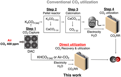
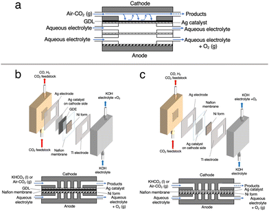
Carbon capture and utilization (CCU) of dilute atmospheric CO2 and industrial exhaust gas is a key to efficient carbon cycling on earth,1,2 and electrochemical CO2 reduction reactions (CO2RRs) using captured CO2 are attracting much attention for the production of chemical feedstocks and fuels from CO2.3,4 The research field of the CO2RR has evolved substantially over the past decade, particularly with the development of a gas diffusion electrode (GDE) in fluidized cathode cells and membrane electrode assemblies (MEAs) to improve the activity, product selectivity, and durability of catalysts.5–7 Direct air capture (DAC) is one of the attractive methods to extract CO2 from the air.8,9 Currently, several DAC systems have been developed; adsorption-based DAC, which uses an alkaline solvent or a porous solid adsorbent to capture CO2 as a carbonate/bicarbonate or other CO2 derivatives, and permeation-based DAC, which consists of a stepwise separation using a membrane (m-DAC).10–13 Unlike the other DAC systems, m-DAC does not require the input of large amounts of thermal energy to desorb CO2 from the adsorbent, although multi-step separation is necessary to produce highly concentrated CO2. Thus, m-DAC combined with the CO2RR using impure CO2 that can be produced by the smaller steps of the m-DAC process, would bypass energy-intensive purification,14–16 and dramatically reduce CCU costs; purification of dilute CO2 gas costs $70–$100 per ton (Fig. 1).17–20 Meanwhile, when using impure CO2 containing O2, the CO2RR is completely blocked in a conventional flow type cell (Fig. 2a and Fig. S1, ESI†) due to the overwhelmingly superior oxygen reduction reaction (O2 + 2H2O + 4e− → 4OH−, ORR) (Fig. S2, ESI†),14,21–23 and therefore most of the CO2RR research has been conducted using pure CO2 gas (> 99%).24–31 Interestingly, direct CO2RR using air-containing mixed gas has been demonstrated using a newly designed flow cell consisting of a non-carbon gas diffusion layer (GDL),14 but the products from the mixed gas still contain O2 and N2, and should be purified before use.Recently, the CO2RR using a bicarbonate solution, which is produced from DAC-captured CO2 gas, has been in focus as an economically feasible CCU method. Here in this study, we explore efficient CO2RR using O2-containing CO2 mixed gas that is captured by m-DAC. In this system, O2 and N2 are first removed by dissolving CO2 in an alkaline solution to bicarbonate, which can be used as a CO2 source and electrolyte. However, in a commonly used flow cell equipped with a carbon-based GDL, the HER is largely promoted when the bicarbonate solution is fed because carbon predominantly promotes the HER rather than the CO2RR (Fig. 2b and Fig. S3, ESI†). To enhance the CO2RR using a bicarbonate solution, we construct a membrane electrode assembly (MEA)-type cell equipped with two liquid flow channels at both the cathode and the anode. In particular, an all-Ag flow channel MEA cell (Ag MEA-cell) was newly designed for substrate diffusion, cathodic reactions and current collection to avoid severe hydrogen evolution reaction (HER) when aqueous solutions are flowing. We applied KHCO3 solution prepared by bubbling a CO2 mixed gas consisting of 40% CO2 and 60% air (air–CO2, where CO2 is enriched by a factor of 1000) into an aqueous 3 M KOH solution. Furthermore, CO2RR was demonstrated by directly introducing air–CO2 to Ag MEA-cell.
Experimental section
Materials
The Ag nanoparticles (Ag NPs <100 nm in diameter) and NafionTM perfluorinated resin solution (5 wt% in a mixture of low aliphatic alcohols and H2O, containing 45% H2O) were purchased from Sigma-Aldrich Co. LLC. Isopropanol (>99.7%), KHCO3 (99%), KOH (>85%), and K2CO3 (99%) were obtained from FUJIFILM Wako Pure Chemical Corporation. All chemicals were used as received without further purification. NafionTM 117 membrane was provided by Chemours. The Ag sheet and the titanium foil were purchased from the Nilaco Corporation. Nickel foam (1.6 mm thick, purity >99.99%) was obtained from MTI Corporation. Oxygen (>99.9%), CO2 (>99.5%), and N2 (>99.9%) were provided by Fukuoka Oxygen Co., Ltd.Preparation of MEA and construction of a flow cell
Cathode electrodes were prepared using a reported air-brushing method.27 Cathodic catalyst ink was prepared by mixing Ag NPs (40 mg), isopropanol (200 μL), deionized H2O (50 μL), and Nafion™ perfluorinated resin solution (80 μL). The ink was airbrushed to a piece of Nafion™ 117 membrane, and allowed to air dry naturally. Unless otherwise noted, the Ag NP-sprayed cathodes were prepared with a catalyst loading of 2.5 mg cm−2. Then, the MEA consisted of a nickel foam anode and a Ag NP-sprayed Nafion™ 117 membrane was prepared (Ag-MEA, Fig. 2c). A Ag MEA-cell was constructed by placing Ag-MEA between a Ag cathode and a Ti anode, with a polyetheretherketone (PEEK) flow plate on the cathode side and a Ti-based flow plate on the anode side. Each electrode was surrounded by silicone rubber for electrical insulation and to seal each compartment.Characterizations
The morphology of the electrodes was evaluated by scanning electron microscopy (SEM) using a JSM-IT100 (JEOL) at 15 kV. The structures of the electrodes were identified by powder X-ray diffraction (XRD) using a D2 Phaser (Bruker).The electrochemical measurement
Electrocatalytic measurements were performed with an electrochemical test system 1280Z (Solartron) in a two-electrode setup (Fig. 2c). 1.0 M KOH aqueous solution was used as the anolyte and fed to the anode compartment of the Ag MEA-cell at a flow rate of 1.0 mL min−1. The cathode compartment was fed with KHCO3 solution (BCS) at a flow rate of 1.0 mL min−1 or reactant gases at a flow rate of 15 ccm. The current density (J) on Ag MEA-cell was calculated based on the Ag cathode area covering Ag-MEA. Gas products were quantified by using a Micro GC FUSION (INFICON). The absence of liquid product was confirmed by high performance liquid chromatography (HPLC) using LC-20AD (Shimadzu) equipped with an RID-10A refractive index detector (Shimadzu). From gas chromatography (GC) and HPLC, no products other than CO and H2 were detected by GC or HPLC. Resistance values for Ag MEA-cells were measured using the 1280Z electrochemical test system. The faradaic efficiencies (FE) were investigated in the cell voltage range of 1.8 to 2.4 V. The FEs for the production of CO (FECO) and H2 (FEH2) were calculated according to the report and the representative results in several experimental tests are shown in this paper.29 Because the size of the cell components was nearly identical, the measured resistances without iR correction were directly used for discussion.Results and discussion
CO2RR using a bicarbonate solution
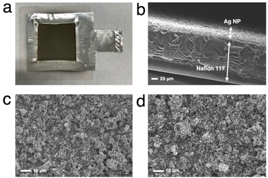
We first tested the CO2RR on a typical MEA cell (Fig. 2b) with Ag NPs applied on a carbon-based gas diffusion electrode (GDE). Chronoamperometry was conducted by flowing 1.0 M BCS as a simulated CO2-captured solution to the cathode side at a flow rate of 1.0 mL min−1 and 1.0 M KOH to the anode side at a flow rate of 1.0 mL min−1. Fig. S3 (ESI†) represents that the FEH2 and FECO values on the MEA cell at 2.0 V of the cell voltage are 16 and 63%, respectively, indicating that the CO2RR can proceed on a carbon-based GDE although the HER is still not negligible in the voltage range between 2.0 and 2.6 V.26,32 It should be noted that the total FE did not reach 100% because of the difficulty in precisely controlling H2 uptake at relatively low potentials in our experimental setup. At a voltage higher than 2.4 V, the HER was further promoted. Several authors have reported that a high overpotential is required to initiate the CO2RR on the carbon-based GDE where the HER is predominant,14,33 and therefore, we constructed a Ag MEA-cell without using a carbon-based GDE (Fig. 2c). Two flow plates with serpentine channels were used to supply 1.0 M KOH and 1.0 M BCS to the anode and the cathode, respectively. We used a PEEK channel to flow BCS on the cathode side because metal electrodes usually promote the HER in CO2RR conducted in an aqueous electrolyte.34,35 In addition, a Ag sheet with a square window was used as the electrode on the cathode side to minimize the contact between the electrode and electrolyte solution (Fig. 2c and 3a). SEM observation confirmed that the surface of the Nafion membrane was uniformly covered with Ag NPs without delamination and significant agglomeration (Fig. 3b–d).We evaluated the CO2RR performance of the Ag MEA-cell using BCS and found that CO and H2 were the only detectable cathodic products based on the analysis of the outlet gas and electrolyte at the cathode compartment. The SEM images of the cathode side of the MEA before and after the reaction showed minimal change in surface morphology during the reaction (Fig. 3c and d). The X-ray diffraction (XRD) pattern of the Ag NPs on the starting MEA indicated characteristic peaks at 38.3, 44.5, 64.7 and 77.7°, corresponding to diffractions from the (111), (200), (220) and (311) planes of Ag, respectively and there was no change in the XRD patterns of the Ag NPs on the MEA before and after the reaction. These results confirmed that the Ag NPs on the cathode maintained their structure under our experimental conditions (Fig. S4 and Table S1, ESI†).
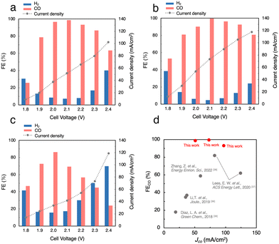
Fig. S5a (ESI†) shows the J, FECO and FEH2 in the CO2RR using 1 M BCS in the voltage range between 1.8 and 2.4 V. As the cell voltage increased, the J gradually increased from 12.2 mA cm−2 at 1.8 V to 59.0 mA cm−2 at 2.4 V. Thus, the CO2RR using BCS was achieved at voltages much lower than 3.0 V and previously reported voltages using a bipolar membrane (BPM).36–38 At 2.0 V, FEH2 became minimal (FEH2 = 9.2%), whereas FECO increased to FECO = 93% with J = 27 mA cm−2, suggesting that a more selective CO2RR occurs compared to those on MEA cells with a carbon-based GDE (FEH2 = 16% and FECO = 63% with J = 30.9 mA cm−2 at 2.0 V, Fig. S3, ESI†). Considering that 3 M BCS is the almost saturated one, we performed the CO2RR using 2 M and 3 M BCSs to increase the efficiency (Fig. 4a and Fig. S5b, ESI†). When 2 M BCS was flowed, we achieved the best performance with FECO > 99% and J = 51.5 mA cm−2 at 2.1 V (Fig. 4a), indicating that almost pure CO was obtained as a CO2RR product. The high selectivity and good J in the CO2RR using 2 M BCS are possibly related to the appropriate balance between the BCS concentration and the solution resistances; 1, 2 and 3 M BCS showed resistances of 1.31, 2.17 and 3.08 Ω, respectively. A comparison of the performance found here with the reported results is summarized in Table S3 (ESI†).
CO2RR using a CO2 capture solution
Next, we performed the CO2RR by flowing a CO2 capture solution, which was prepared by bubbling pure CO2 gas into 1.0 M KOH (CO2-sol, pH 7.55, Table S2, ESI†) as the electrolyte, and achieved FECO > 99% and J = 73.3 mA cm−2 at 2.1 V (Fig. 4b). Interestingly, FECO remained at 93% even with a relatively high J = 105 mA cm−2 at 2.3 V, which implies that the J values in the CO2RR using CO2-sol are higher than those in BCSs. The reported MEA cells using BCS mostly used a BPM, which requires a large overpotential of more than 3.0 V for the dissociation of H2O into H+ and OH− at the membrane (H2O(l) ⇌ H+(aq) + OH−(aq)).36–38 In contrast, our Ag MEA-cell made of a Nafion membrane can eliminate the need for H2O dissociation. Furthermore, the Ag MEA-cell showed higher FECO and higher J compared to the previously reported performances, which exhibits great potential of CO2RRs for the direct utilization of BCS as a CO2 resource.36–39We then demonstrated the CO2RR using a CO2 capture solution prepared by bubbling air–CO2 into 3 M KOH (air–CO2-sol). The pH of air–CO2-sol was 7.90 (Table S2, ESI†), indicating that bicarbonate is the primary carbon species in air–CO2-sol.40 A high FECO of 86% with J = 33.4 mA cm−2 in the CO2RR using air–CO2-sol was realized at 2.0 V (Fig. 4c), indicating that the Ag MEA-cell exhibits significantly high selectivity for CO production even using air–CO2-sol and a high possibility for direct utilization of various impure CO2 sources.
CO2RR using 60% air containing CO2
We tried to directly apply air–CO2 as a reactant gas to Ag MEA-cell. As mentioned above, the inclusion of O2 in the reactant gas is known to completely inhibit the progress of the CO2RR in a conventional electrochemical flow cell due to highly preferential ORR.14,22 In fact, we performed the CO2RR by feeding air–CO2 into a conventional flow cell using a carbon-based GDE on which Ag NPs were applied (Fig. 2a and Fig. S1, ESI†),23,26,32 but did not observe any products, neither CO nor H2 (Fig. S2, ESI†). This result implies that CO2 does not interact with the Ag catalyst on the carbon GDE in the presence of air and that the current flowing into the GDE is predominantly used for the ORR before the onset of the CO2RR, which is explained by the fast kinetics of the ORR.41–44 It should be recalled that the newly designed Ag MEA-cell has a unique structure in which the reactant gas can directly contact the Ag NP catalyst, implying the possibility of the CO2RR on Ag MEA-cell even with air–CO2. Before investigating the CO2RR with air–CO2, the CO2RR performance on the Ag MEA-cell was examined by flowing pure CO2 to the cathode side. Fig. S6 (ESI†) represents that J increases with increasing cell voltage, reaching 100 mA cm−2 at 2.3 V and the CO2RR using pure CO2 gas shows more than 2 times better J between 2.0 and 2.4 V compared to the CO2RR using 1 M BCS. The voltage was considerably small compared to the reported voltage of 3.5 V on a BPM-equipped MEA cell showing the large overpotential on a BPM to dissociate H2O into H+ and OH−.45–47 Furthermore, we achieved FECO = 97% at 2.3 V and J = 100 mA cm−2 using the optimized Nafion loading on Ag-MEA (Fig. S7 and S8a, ESI†). To investigate the effect of CO2 concentration, we used a mixed gas consisting of 40% CO2 and 60% N2 (N2-CO2) for the CO2RR in the voltage range of 2.0 to 2.4 V with 10% Nafion loading on Ag-MEA under the optimized conditions (Fig. S8b, ESI†). We found that the selectivity for the CO2RR is significantly reduced when using N2-CO2, especially at higher cell voltages above 2.3 V (Fig. 5a and b). For example, the FECO was reduced to 48% at 2.4 V compared to FECO = 93% at 2.4 V for pure CO2, whereas FEH2 was significantly increased to 43%, suggesting that the HER is promoted at low CO2 concentration.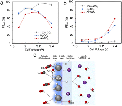 | ||
| Fig. 5 (a) FE for CO production (FECO) and (b) for the HER (FEH2) in the CO2RR using N2-CO2 and air–CO2. (c) Predicted mechanism of the CO2RR on the Ag MEA-cell. | ||
Subsequently, air–CO2 was used as a CO2 source to examine the effect of O2 inclusion on the CO2RR. The CO2RR in the Ag MEA-cell reached FECO = 74% and J = 56.7 mA cm−2 at 2.2 V (Fig. S8c, ESI†), which is analogous to FECO = 76% and J = 39.9 mA cm−2 at 2.2 V for N2–CO2 (Fig. S8b, ESI†), indicating that the decrease in FECO is caused by the low CO2 concentration, not by the enhancement of the ORR. When the CO2RR was performed above 1.9 V, the total FE values or the sum of FECO and FEH2 became less than 100%, which suggests that a part of the flowed current is used for the ORR, and the HER was increased above 2.3 V. Thus, the favorable FECO in the CO2RR with using air–CO2 between 2.0 and 2.2 V is possibly explained by the previously reported phenomenon;42 a thin layer of H2O is formed on the Ag catalyst surface by the ORR, which prevents O2 from contacting the Ag catalyst surface as shown in Fig. 5c. In addition, the H2O produced by the ORR increases the moisture content of the Nafion membrane, which reduces its insulating properties and results in a relatively high J value.
Conclusion
The newly constructed Ag MEA-cell significantly suppresses the HER, which makes it applicable to the CO2RR using BCS. After the detailed optimization of the reaction conditions, we have achieved the maximum FECO > 99% and partial current density for CO production (JCO) of 73.3 mA cm−2 in the CO2RR using 1.0 M CO2-sol. Even when we used air–CO2-sol, high CO selectivity FECO = 86% with 33.4 mA cm−2 was achieved at 2.0 V (Table 1). Furthermore, excellent CO selectivity with FECO = 74% and relatively high J = 52.7 mA cm−2 were realized by direct application of air–CO2 to Ag MEA-cell, suggesting a selective CO2RR with suppressed ORR even using air–CO2 due to the unique structure of the Ag MEA-cell where the contact points between air–CO2 and the electrode were minimized. These results showed that the Ag MEA-cell structure has high potential for the direct conversion of CO2 feedstocks captured by DAC, which would broaden the applicability of the combination of DAC and CO2RR technologies.| Entry | CO2 source | Cell voltage (V) | FECO (%) | J (mA cm−2) |
|---|---|---|---|---|
| 1 | 2 M BCS | 2.1 | >99 | 51.5 |
| 2 | CO2-sol | 2.1 | >99 | 73.3 |
| 3 | Air–CO2-sol | 2.0 | 86 | 33.4 |
| 4 | CO2 | 2.3 | 97 | 100 |
| 5 | Air–CO2 | 2.2 | 74 | 56.7 |
Author contributions
A. Y. and M. H. designed the experiments and M. Y. supervised the project. M. H. performed the electrolyzer experiments. A. A and A. Y. measured XRD, and A. A., A. Y. and M. H. measured SEM of the MEAs. A. Y. and M. H. defined the reactions in the flow cell. A. Y. performed the data analysis. A. Y. wrote the first manuscript draft and all authors contributed to manuscript writing.This work was supported by NEDO the Moonshot Research and Development Program (JPNP18016) and JSPS KAKENHI (JP22K19088, JP23H00313).
Conflicts of interest
The authors declare no competing financial interest.Notes and references
- J. Artz, T. E. Müller, K. Thenert, J. Kleinekorte, R. Meys, A. Sternberg, A. Bardow and W. Leitner, Chem. Rev., 2018, 118, 434–504 CrossRef CAS PubMed.
- H.-J. Ho, A. Iizuka and E. Shibata, Ind. Eng. Chem. Res., 2019, 58(21), 8941–8954 CrossRef CAS.
- J. Qiao, Y. Liu, F. Hong and J. Zhang, Chem. Soc. Rev., 2014, 43, 631–675 RSC.
- O. G. Sánchez, Y. Birdja, M. Bulut, J. Vaes, T. Breugelmans and D. Pant, Curr. Opin. Green Sustainable Chem., 2019, 16, 47–56 CrossRef.
- G. Díaz-Sainz, M. Alvarez-Guerra, B. Ávila-Bolívar, J. Solla-Gullónb, V. Montiel and A. Irabiena, J. Chem. Eng., 2021, 405, 126965 CrossRef.
- W. Lee, Y. E. Kim, M. H. Youn, S. K. Jeong and K. T. Park, Angew. Chem., Int. Ed., 2018, 57, 6883–6887 CrossRef CAS PubMed.
- Y. C. Li, G. Lee, T. Yuan, Y. Wang, D.-H. Nam, Z. Wang, F. P. García de Arquer, Y. Lum, C.-T. Dinh, O. Voznyy and E. H. Sargent, ACS Energy Lett., 2019, 4(6), 1427–1431 CrossRef CAS.
- E. S. Sanz-Pérez, C. R. Murdock, S. A. Didas and C. W. Jones, Chem. Rev., 2016, 116(19), 11840–11876 CrossRef PubMed.
- A. Sodiq, Y. Abdullatif, B. Aissa, A. Ostovar, M. Nassar, M. El-Naas and A. Amhamed, Environ. Technol. Innov., 2023, 29, 102991 CrossRef CAS.
- O. Selyanchyn, R. Selyanchyn and S. Fujikawa, ACS Appl. Mater. Interfaces, 2020, 12(29), 33196–33209 CrossRef CAS PubMed.
- S. Fujikawa, R. Selyanchyn and T. Kunitake, Polym. J., 2021, 53, 111–119 CrossRef CAS.
- S. Fujikawa and R. Selyanchyn, MRS Bull., 2022, 47, 416–423 CrossRef CAS.
- R. Castro-Muñoz, M. Z. Ahmad, M. Malankowska and J. Coronas, J. Chem. Eng., 2022, 446(2), 137047 CrossRef.
- A. Anzai, M. Higashi and M. Yamauchi, Chem. Commun., 2023, 59, 11188–11191 RSC.
- D. M. D'Alessandro, B. Smit and J. R. Long, Angew. Chem., Int. Ed., 2010, 49, 6058–6082 CrossRef PubMed.
- M. E. Boot-Handford, J. C. Abanades, E. J. Anthony, M. J. Blunt, S. Brandani, N. Mac Dowell, J. R. Fernández, M.-C. Ferrari, R. Gross, J. P. Hallett, R. S. Haszeldine, P. Heptonstall, A. Lyngfelt, Z. Makuch, E. Mangano, R. T. J. Porter, M. Pourkashanian, G. T. Rochelle, N. Shah, J. G. Yao and P. S. Fennell, Energy Environ. Sci., 2014, 7, 130–189 RSC.
- M. T. Ho, G. W. Allinson and D. E. Wiley, Energy Procedia, 2009, 1, 763–770 CrossRef CAS.
- R. F. Service, Science, 2016, 354, 1362–1363 CrossRef CAS PubMed.
- B. Kim, S. Ma, H.-R. M. Jhong and P. J. A. Kenis, Electrochim. Acta, 2015, 166, 271–276 CrossRef CAS.
- M. Erans, E. S. Sanz-Pérez, D. P. Hanak, Z. Clulow, D. M. Reiner and G. A. Mutch, Energy Environ. Sci., 2022, 15, 1360–1405 RSC.
- D. Kim, W. Choi, H. W. Lee, S. Y. Lee, Y. Choi, D. K. Lee, W. Kim, J. Na, U. Lee, Y. J. Hwang and D. H. Won, ACS Energy Lett., 2021, 6, 3488–3495 CrossRef CAS.
- S. Polani, N. Kanovsky and D. Zitoun, ACS Appl. Nano Mater., 2018, 1, 3075–3079 CrossRef CAS.
- F. Li, C. Zhou, E. Feygin, P.-N. Roy, L. D. Chen and A. Klinkova, Phys. Chem. Chem. Phys., 2022, 24, 19432–19442 RSC.
- M. R. Thorson, K. I. Siil and P. J. A. Kenis, J. Electrochem. Soc., 2013, 160, F69 CrossRef CAS.
- B. Kim, S. Ma, H.-R. M. Jhong and P. J. A. Kenis, Electrochim. Acta, 2015, 166, 271–276 CrossRef CAS.
- S. Ma, R. Luo, J. I. Gold, A. Z. Yu, B. Kim and P. J. A. Kenis, J. Mater. Chem. A, 2016, 4(22), 8573–8578 RSC.
- S. Ma, M. Sadakiyo, R. Luo, M. Heima, M. Yamauchi and P. J. A. Kenis, J. Power Sources, 2016, 301, 219–228 CrossRef CAS.
- S. Ma, M. Sadakiyo, M. Heima, R. Luo, R. T. Haasch, J. I. Gold, M. Yamauchi and P. J. A. Kenis, J. Am. Chem. Soc., 2017, 139(1), 47–50 CrossRef CAS PubMed.
- A. Anzai, M.-H. Liu, K. Ura, T. G. Noguchi, A. Yoshizawa, K. Kato, T. Sugiyama and M. Yamauchi, Catalysts, 2022, 12, 478 CrossRef CAS.
- M. Sun, A. Staykov and M. Yamauchi, ACS Catal., 2022, 12(24), 14856–14863 CrossRef CAS.
- M. Sun, J. Cheng and M. Yamauchi, Nat. Commun., 2024, 15, 491 CrossRef CAS PubMed.
- Q. Lu, J. Rosen, Y. Zhou, G. S. Hutchings, Y. C. Kimmel, J. G. Chen and F. Jiao, Nat. Commun., 2014, 5, 3242 CrossRef PubMed.
- K. Yang, R. Kas, W. A. Smith and T. Burdyny, ACS Energy Lett., 2021, 6, 33–40 CrossRef CAS.
- Y. Hori, H. Wakebe, T. Tsukamoto and O. Koga, Electrochim. Acta, 1994, 39, 1833–1839 CrossRef CAS.
- Y. J. Sa, C. W. Lee, S. Y. Lee, J. Na, U. Lee and Y. J. Hwang, Chem. Soc. Rev., 2020, 49, 6632–6665 RSC.
- T. Li, E. W. Lees, M. Goldman, D. A. Salvatore, D. M. Weekes and C. P. Berlinguette, Joule, 2019, 3, 1487–1497 CrossRef CAS.
- E. W. Lees, M. Goldman, A. G. Fink, D. J. Dvorak, D. A. Salvatore, Z. Zhang, N. W. X. Loo and C. P. Berlinguette, ACS Energy Lett., 2020, 5, 2165–2173 CrossRef CAS.
- Z. Zhang, E. W. Lees, F. Habibzadeh, D. A. Salvatore, S. Ren, G. L. Simpson, D. G. Wheeler, A. Liu and C. P. Berlinguette, Energy Environ. Sci., 2022, 15, 705–713 RSC.
- L. A. Diaz, N. Gao, B. Adhikari, T. E. Lister, E. J. Dufek and A. D. Wilson, Green Chem., 2018, 20, 620–626 RSC.
- J. Zosel, W. Oelßner, M. Decker, G. Gerlach and U. Guth, Meas. Sci. Technol., 2011, 22, 072001 CrossRef.
- M. Chatenet, L. Genies-Bultel, M. Aurousseau, R. Durand and A. Andolfatto, J. Appl. Electrochem., 2002, 32, 1131–1140 CrossRef CAS.
- L. Tammeveski, H. Erikson, A. Sarapuu, J. Kozlova, P. Ritslaid, V. Sammelselg and K. Tammeveski, Electrochem. Commun., 2012, 20, 15–18 CrossRef CAS.
- Z. Chen, C. Li, Y. Ni, F. Kong, Y. Zhang, A. Kong and Y. Shan, Electrochim. Acta, 2017, 239, 45–55 CrossRef CAS.
- H. Erikson, A. Sarapuu and K. Tammeveski, ChemElectroChem, 2019, 6, 73–86 CrossRef CAS.
- D. A. Salvatore, D. M. Weekes, J. He, K. E. Dettelbach, Y. C. Li, T. E. Mallouk and C. P. Berlinguette, ACS Energy Lett., 2018, 3, 149–154 CrossRef CAS.
- C. P. O’Brien, R. K. Miao, S. Liu, Y. Xu, G. Lee, A. Robb, J. E. Huang, K. Xie, K. Bertens, C. M. Gabardo, J. P. Edwards, C.-T. Dinh, E. H. Sargent and D. Sinton, ACS Energy Lett., 2021, 6, 2952–2959 CrossRef.
- K. Yang, M. Li, S. Subramanian, M. A. Blommaert, W. A. Smith and T. Burdyny, ACS Energy Lett., 2021, 6, 4291–4298 CrossRef CAS PubMed.
Footnote |
| † Electronic supplementary information (ESI) available. See DOI: https://doi.org/10.1039/d4ya00038b |
| This journal is © The Royal Society of Chemistry 2024 |

