Electroreforming of plastic wastes for value-added products
Ying
Li
 a,
Lang
Liu
a,
Li Quan
Lee
a,
Lang
Liu
a,
Li Quan
Lee
 b and
Hong
Li
 *b
*b
aCollege of Energy Engineering, Xi’an University of Science and Technology, Xi’an 710054, China
bSchool of Mechanical and Aerospace Engineering, Nanyang Technological University, 639798, Singapore. E-mail: ehongli@ntu.edu.sg
First published on 21st November 2024
Abstract
The problem of plastic pollution is becoming increasingly serious, and there is an urgent need to reduce the use of plastics and to improve the recovery rate of plastic wastes. Plastic wastes can be transformed into value-added chemicals at the anode through electrocatalytic conversion, while coupling with cathodic reduction reactions to achieve cogeneration of valuable anodic and cathodic products. The plastic electroreforming technology has unprecedented advantages, including a green and decentralizable process, renewable energy storage, ecological benefits, resource recovery, cost-effectiveness, and so on. Herein, we present a mini review about recent advances in this topic. We first discuss the electrooxidation mechanisms of different plastic wastes (such as polylactic acid, polyethylene glycol terephthalate, polyethylene, polyethylene furanoate, polybutylene terephthalate, and polyamides). Then, the progress of plastic waste-assisted electrolysis systems is summarized, including plastic waste-assisted water splitting for hydrogen production and oxygen reduction, as well as plastic electroreforming coupled with CO2 reduction, and the nitrate reduction reaction. Finally, the development prospects and challenges in this field are introduced and discussed. This review aims to provide a concise overview of the emerging plastic electroreforming, thus offering insight on the design of efficient and stable plastic-assisted electrolysis systems.
1. Introduction
Plastics, indispensable and important raw materials in modern society, have been hailed as some of the most important inventions in the 20th century. It is widely used in packaging, automobiles, agriculture, electronics, construction, medical and other fields owing to their advantages, such as eminent chemical resistance, low manufacturing costs, good insulating properties, light weight, etc.1–3 However, every coin has two sides, and so do plastics. The flip side of the coin is wasted plastics impose a heavy burden on the society and environment. Statistically, the global plastic production showed an exponential growth trend with 2.1 million tons in 1950, 147 million tons in 1993, and 360 million tons in 2018.4 As of 2018, more than 6.3 billion tons of plastic wastes have been generated. Among them, 79% was disposed or landfilled, 12% was incinerated and only about 9% of plastic wastes were recycled.5–7 Plastic wastes in the environment may not be decomposed for decades to centuries due to their stable physical and chemical structures, which causes the death of many marine animals every year. Worryingly, microplastics produced by the decomposition of plastic wastes have entered the human body. A report shows that, among the human blood samples from 22 healthy volunteers, nearly 80% contained plastic particles ≥700 nm.8 Ragusa et al. collected the human breastmilk samples from 34 women and found microplastics in 26 samples using Raman microspectroscopy.9 The problem of plastic pollution is becoming more and more serious, and it is urgent to reduce the use of plastics and to improve the recycling rate of plastic wastes.To date, various technologies have been developed for plastic waste recycling, including physical recycling, chemical decomposition, biodegradation, electrocatalysis and so on. Physical recycling is an environmentally friendly technique with low recycling cost and a simple process, but it requires a higher quality of plastic wastes and the application range of physical recycling of plastic wastes is very narrow.10,11 The chemolysis of plastic wastes is generally carried out at temperatures ranging from 300 to 900 °C, which usually produces products such as CO, CO2 and H2, and requires the presence of a catalyst.12,13 The biodegradation of plastic wastes is regarded as an eco-friendly treatment that does not produce any by-products, but it often requires expensive living organisms or microorganisms and a relatively long period.14 Compared to these methods, electrocatalytic plastic upgrading technology has the following advantages: (i) resource and energy recovery of plastic wastes, and reduction of carbon dioxide emissions; (ii) mild reaction conditions (e.g. atmospheric pressure and room temperature); (iii) an economic and environmentally friendly process with renewable electricity; (iv) storage of renewable electricity; and (v) cogeneration of value-added cathodic and anodic products.15–18
In recent years, electrocatalytic plastic waste valorization technology has attracted increasing attention, and a range of research works have been reported on the electrocatalytic oxidation of plastics wastes to prepare high-value chemicals and clean fuels. Nevertheless, most studies focus on catalyst design, lacking a systematic summary of the electrochemical conversion of various plastic wastes. Recently, several relevant reviews have been published. For example, Peng et al. systematically summarized the progress in renewable energy-driven plastic photocatalysis, electrocatalysis, and photo/electro integrated conversion, involving the design of different catalysts, as well as the working principles and targets.19 Qiu and his team reviewed the pre-treatment methods for plastic solid wastes, emphasizing using advanced catalysts in plastic electrochemical reactions, and evaluating their corresponding technical–economic feasibility.20 Choi et al. outlined the electrochemical recycling technologies for various types of plastic wastes, explored their potential to produce value-added products and emphasized the importance of developing of electrocatalysts and electrochemical reaction systems.18 To distinguish from these review articles, this review focuses on the electroreforming process of different types of plastic wastes and integrated systems coupling various types of cathodic reduction reactions. Specifically, we introduce the electrocatalytic mechanism of different plastics, including polylactic acid (PLA), polyethylene glycol terephthalate (PET), polyethylene (PE), polyethylene furanoate (PEF), polybutylene terephthalate (PBT), polyamides (PA) and so on. Then, the research on coupling the cathode reactions (such as the hydrogen evolution reaction, oxygen reductive reaction, CO2 reduction reaction and nitrate reduction reaction) with the electrooxidation of plastic wastes is discussed. Finally, we point out the remaining challenges and the opportunities for future development of such coupling systems.
2. Electrooxidation mechanism of plastic wastes
Plastic wastes need to undergo hydrolysis before being electroreformed, and the resulting hydrolyzed products will be converted into high-value chemicals through electrocatalytic oxidation. Various hydrolysis techniques have been explored, including alkaline,21,22 acid,23,24 neutral25 and enzymatic26 hydrolysis. Among them, alkaline hydrolysis has garnered significant attention due to low cost and high efficiency. Reaction parameters (e.g., alkali concentration, reaction temperature, reaction time and plastic size) play a crucial role in determining product purity and yield in the process of plastic hydrolysis. Furthermore, the efficiency of alkaline hydrolysis of plastics can be greatly improved by utilizing microwave-assisted methods,27–29 ultrasound-assisted techniques30 or introducing alcohol solvents (e.g., ethanol, methanol, and dimethyl isosorbide).31,322.1. PLA electrooxidation process
The polylactic acid (PLA) plastic is a polymer derived from lactic acid monomers generated by the diastatic fermentation process. Bio-based plastics represented by PLA are considered to be an ideal alternative to petroleum-based non-degradable plastics. However, the microbial decomposition process of the PLA plastic waste is seen as a waste of carbon resources and inevitably leads to CO2 emissions. Thus, it not only reduces carbon footprint, but also achieves waste recycling by using discarded PLA wastes as a feedstock for the sustainable production of high-value chemicals.The electrochemical oxidation process of the PLA plastic waste includes two parts. PLA is first converted into lactic acid monomers through alkaline hydrolysis, and then lactic acid can be used to produce high-value chemicals by electrooxidation reactions.33 For example, Li et al. synthesized a nickel phosphide (Ni2P/NF) electrocatalyst by electrochemical deposition and phosphide treatment, which successfully converted PLA into acetate and acetonate, and showed a high acetate selectivity of more than 80% and a lactate conversion of ∼100% after prolonged electrolysis. (Fig. 1A–F).34 The proposed reaction pathways for the electrooxidation of PLA are depicted in Fig. 1G. Before the electrocatalytic process, the PLA plastic was hydrolyzed to obtain lactate in an alkaline solution. The electrooxidation products of lactate were detected via ion chromatography, and the results showed that the primary product was acetate, accompanied by a small amount of acetonate.34 Zhang et al. believed that lactic acid first undergoes a dehydrogenation process to form pyruvic acid. The C–C bond on pyruvic acid was subsequently broken, forming acetic acid and carbonate (Fig. 1G). And the selectivity of acetic acid is approximately 95.2% at 20 mA cm−2.33 Gao's team detected the electrocatalytic oxidation products of PLA using gas chromatography-flame ionization detection and found that 80.73 mM acetic acid was produced in the electrolyte after 30-h electrolysis, indicating that the conversion rate of PLA plastic electrooxidation to acetic acid is about 87%.35 Innovatively, Qiu et al. converted lactate to pyruvate via pulse electrooxidation on a Pd/Ni (OH)2 electrocatalyst obtained in the PLA hydrolysis, followed by electrochemical reductive amination to ultimately convert pyruvate to alanine using a TiO2 catalyst.36
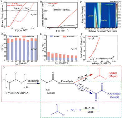 | ||
| Fig. 1 (A) Performance of the electrocatalytic lactate oxidation over the Ni2P/NF electrocatalyst in alkaline media with and without potassium lactate (KLA). (B) LSV curves of pure NF and Ni2P/NF electrodes in alkaline media with 0.2 M KLA. (C) Plot of the concentration of the reactants and products with reaction time. The Faraday efficiency (FE) of products at different current densities for (D) the Ni2P/NF electrode and (E) the pure NF electrode. (F) Variation in the normalized acetate partial current density against the applied voltage over pure NF and Ni2P/NF electrodes.34 Copyright 2024 American Chemical Society. (G) Proposed reaction mechanism for the electrooxidation of PLA in an alkaline electrolyte.33,34 | ||
2.2. PET electrooxidation process
In an alkali solution, the C![[double bond, length as m-dash]](https://www.rsc.org/images/entities/char_e001.gif) O double bond present in PET plastic undergoes cleavage, resulting in the formation of smaller molecules named terephthalates and ethylene glycol. Ethylene glycol (EG) can be further converted into value-added chemicals such as formic acid or glycolic acid through electrocatalytic oxidation, while terephthalate can be precipitated by acid treatment to be used as a monomer for making new PET. The electrooxidation process of EG can be summarized as the C1 pathway and the C2 pathway according to its electrocatalytic products. The detailed reaction pathways are discussed below.
O double bond present in PET plastic undergoes cleavage, resulting in the formation of smaller molecules named terephthalates and ethylene glycol. Ethylene glycol (EG) can be further converted into value-added chemicals such as formic acid or glycolic acid through electrocatalytic oxidation, while terephthalate can be precipitated by acid treatment to be used as a monomer for making new PET. The electrooxidation process of EG can be summarized as the C1 pathway and the C2 pathway according to its electrocatalytic products. The detailed reaction pathways are discussed below.
The formation of formic acid by EG typically involves a series of oxidation reactions. As shown in Fig. 2A and B, Zhao and his team proposed that EG molecules initially adsorb on the surface of the CoOOH active substance produced by CuO electrochemical activation, resulting in the formation of *OHCH2–CH2OH. In comparison to the endothermic reaction forming a glycolaldehyde intermediate (*OCH–CH2OH), *OHCH2–CH2OH is more inclined to undergo deprotonation of –OH, resulting in the loss of 2 electrons and then transformation into an alkoxide intermediate (*OCH2–CH2O). Afterward, the *OCH2–CH2O intermediate lost 2 electrons and was oxidized to the glyoxal intermediate (*OCH–HCO). Finally, the C–C bond in the *OCH–HCO intermediate cleaves to produce formic acid (HCOOH).37 The results of product analysis suggest that the formic acid yield and the faradaic efficiency of EG conversion reach ∼86.5% and 88%, respectively.37
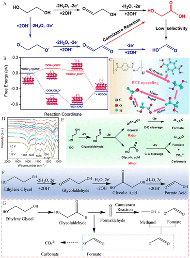 | ||
| Fig. 2 (A) Proposed reaction mechanism for the electrooxidation of EG to HCOOH in alkaline media and (B) the free energy change of EG electrooxidation on the CuO electrode by different pathways.37 Copyright 2022 American Chemical Society. (C) Sketch map of the PET plastic waste upcycling process.38 Copyright 2024 Elsevier. (D) In situ FTIR spectra of the CuCo2O4 NWA/NF electrocatalyst in 1.0 M KOH with EG solution. (E) Presented reaction routes for the electrooxidation of EG to form formates over a CuCo2O4 NWA/NF electrocatalyst.39 Copyright 2022 Royal Society of Chemistry. (F) Presented reaction routes for the electrooxidation of EG to form formic acid over a NiCu/NF electrocatalyst.40 (G) Presented reaction routes for the electrooxidation of EG to form formates over a Co-Ni3N/CC electrocatalyst.41 Copyright 2022 Tsinghua University Press. | ||
When the electrocatalysts are different, the electrooxidation reaction pathway of EG is also slightly different. For example, Wang and his team used a Pd–NiTe/NF electrocatalyst for the electrooxidation of PET hydrolysates, and they revealed that the reaction pathway of Pd–NiTe/NF electrodes in catalyzing the PET waste under alkaline conditions is as follows (Fig. 2C).38 First, PET is hydrolyzed to produce PTA and EG, and the O–H bond in EG is broken, catalyzing the oxidation to the glycolaldehyde intermediate (*CH2OH–CHO), and then the *CH2OH–CHO intermediate is decomposed into formates through rapid C–C oxicracking. Furthermore, a few of *CH2OH–CHO are oxidized to glycolic acid, which is then slowly C–C cleaved to form formates. Chen et al. reported a cobalt-based spinel oxide CuCo2O4 nanowire array/Ni foam electrode for electrooxidation of polyester plastics and analyzed the EGOR process through in situ FTIR spectroscopy. As depicted in Fig. 2D, peaks at 1110 and 1290 cm−1 were ascribed to the stretching vibration of aldehyde from OHCCHO and the C–O stretch of GA, respectively. The peaks at 1350, 1432 and 1582 cm−1 can be assigned to COO− of the GA and formate species. It is worth noting that small amounts of GA impurities were also detected by 1H and 13C NMR spectroscopic analyses. Then, Chen et al. further calculated the free energy change from *CH2OH–CHO to *OCH–HCO (1.08 eV), which is lower than that for the formation of *glycolic acid (1.30 eV). These results indicate that *OCH–HCO is the major intermediate (Fig. 2E).39 A similar reaction pathway for the conversion of EG to HCOOH occurs at Pt1/Ni (OH)2 electrocatalysts.42 However, Kang et al. revealed that CH2OH–COOH oxidation is kinetically and thermodynamically easier than OCH–HCO oxidation, indicating that the pathway of EG–glycolic acid–formic acid is the main route for the electrooxidation of PET plastics on the NiCu/NF electrocatalysts (Fig. 2F).40 Importantly, the NiCu60s/NF electrocatalyst offered an optimal formate selectivity (FE, 95.8%) and yield rate (0.70 mmol cm−2 h−1).40
As depicted in Fig. 2G, the reaction pathway for the electrooxidation of EG at Co–Ni3N/CC electrodes in a 1 M KOH electrolyte was proposed by Chen and his team.41 Different from previous reports, the C–C bond in the *HOCH2–COH intermediate undergoes oxidative cleavage to form *HCOO− and *HCOH products. And *HCOH experiences a Cannizzaro reaction in an alkaline electrolyte, resulting in the formation of *HCOO− and *CH3OH. Finally, *CH3OH is further electrooxidized to *HCOO−.
Shi's team developed a PdAg alloy electrocatalyst on the nickel foam (NF), which can efficiently electrooxidize EG to high value-added GA and exhibit superior 92% faradaic efficiency of the GA product at 0.91 V vs. RHE.43 Studies have shown that in the bimetallic synergistic catalytic process, the C2 intermediate (HOCH2–CHO) generated by the dehydrogenation reaction of EG is adsorbed on the surface of the PdAg electrode and then is catalyzed by Pd to produce GA, without C–C bond breaking to obtain the C2 product (Fig. 3). Yang and his team successfully obtained the Pt–Mn2O3 interfacial sites to boost selective electrooxidation of EG to GA under mild conditions. The research results indicate that the synergistic effect between the Pt and Mn2O3 redox cycle makes the dehydrogenation of the C–H bond easier, thereby enhancing the electrooxidation activity of EG.44
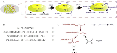 | ||
| Fig. 3 (A) and (B) Proposed mechanism for EG electrooxidation on PdAg/NF. (C) Probable reaction route of EG electrooxidation.43 Copyright 2021 Cell Press. | ||
Chen and his team constructed a Pd–Ni(OH)2 electrode, which selectively electrooxidized EG to glycolic acid (GA) by the synergistic interaction of Ni and Pd active sites.45 In order to further understand the EGOR process, electrochemical in situ FTIR analysis was performed on Pd–Ni(OH)2 and Pd. As illustrated in Fig. 4A and B, the peak at 1660 cm−1 was ascribed to interfacial H2O and the *OC–CH2OH intermediates. The peak at 1070 cm−1 can be assigned to the stretching vibration of aldehyde from OHCCHO and GA species. In addition, different from Pd at 0.7 V, for the Pd–Ni(OH)2 electrode at 0.4 V (based on the generation potential of *OH adsorption), the peaks at 1570 and 1320 cm−1 were attributed to antisymmetric and symmetric stretching bands of COO− in GA, respectively, and enhanced with the increase of potential. The above results indicate that the *OH adspecies can quickly convert *OC–CH2OH into GA. Therefore, the specific electrooxidation reaction pathways from the EG to GA are depicted in Fig. 4C and D, i.e., *HOCH2–CH2OH → *OCH2–CH2OH → *CHO–CH2OH → *CO–CH2OH → *COOH–CH2OH. Unlike the C–C bond cleavage of *HOC–CHO or * HOCH2–CHO intermediates in the C1 reaction pathway, *OH on the adjacent Ni–Pd site couples with *CO–CH2OH to generate *COOH–CH2OH on the Pd-Ni(OH)2 electrode, which is easily desorbed from the Pd active site to the adjacent Ni active site, thereby restraining the C–C bond breaking. The electrooxidation reaction pathway for EG-to-GA on the pure Pt electrode is consistent with that reported by Chen et al. Unlike the *OCH2–CH2OH intermediate, Du et al. revealed that the EG molecules adsorbed on Ni sites (*EG) undergo the deprotonation process to produce 1,2-dihydroxy-ethyl (*CHOH–CH2OH) on Pt/γ-NiOOH/NF electrocatalysts (Fig. 4E).46 In addition, Pt/γ-NiOOH/NF electrocatalysts exhibit a superior faradaic efficiency (>90%) and selectivity (>90%) for glycolate production.46
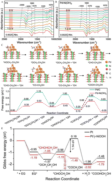 | ||
| Fig. 4 Electrochemical in situ FTIR spectra of (A) Pd and (B) Pd–Ni(OH)2.45 Copyright 2023 Wiley. (C) Proposed reaction pathway of the EG electrooxidation on the Pd–Ni(OH)2 catalyst and (D) calculated free energy change for GA generation on Pd and Pd–Ni(OH)2 electrodes.45 Copyright 2023 Wiley. (E) Gibbs free energy graphs for EG-to-GA electrooxidation on Pt and Pt/γ-NiOOH electrodes.46 Copyright 2023 Wiley-VCH GmbH. | ||
2.3. Electrooxidation process of other plastic wastes
In addition to PET and PLA plastic wastes, the electrolytic study of plastics such as polyethylene (PE), polyethylene furanoate (PEF), polybutylene terephthalate (PBT) and polyamides (PA) has also been reported.For example, PE, as one of the most common plastics, could take hundreds to thousands of years to naturally degrade. Reisner et al. successfully converted the PE plastic into dicarboxylic acids (containing 22% glutaric acid and 44% succinic acid) with the help of 6 wt% HNO3, then the dicarboxylic acids were electrocatalytically converted to gaseous hydrocarbon products of ethylene and propylene using a carbon electrode (Fig. 5A).47
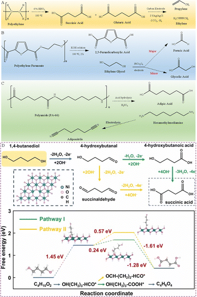 | ||
| Fig. 5 (A) Presented reaction route of PE plastics converted into alkenes.47 (B) Presented reaction route of PEF electrooxidation in an alkaline electrolyte.48 (C) Presented reaction route of end-of-life PA-66 recycling.49 (D) Presented reaction route of BDO oxidation in an alkaline electrolyte and calculated free energy change for BDO oxidation to succinic acid.50 Copyright 2023 Elsevier. | ||
PEF is a 100% bio-based material, a recyclable and degradable polymer. It has good resistance against CO2 and O2, thereby extending the lifespan of packaged products. In addition, it has high mechanical strength, which means thin PEF packaging can be used and thus few resources are required. These additional features combined with plant-based raw materials endow PEF with all the attributes for the next generation polyester. This makes bio-based PEF considered one of the ideal alternatives to PET, especially in the field of plastic packaging. Similar to PET plastics, PEF plastics first dissolve in an alkali electrolyte, and then the PEF hydrolysate is electrooxidized. Zhao's team has synthesized a NiCo2O4 electrocatalyst, which has been used for the selective electrooxidation of PEF hydrolysates to produce FA. More specifically, PEF plastics first reacted in an alkaline medium for 2 h at 180 °C to generate FDCA and EG, then the EG in the electrolyte is electrooxidized to FA, accompanied by the formation of a small amount of GA (Fig. 5B). And the NiCo2O4 electrode exhibits a high FE of 98% and 85.8% conversion for formate generation at 1.40 V.48
Polyamide-66 (PA-66) has the highest mechanical strength and is most widely used among PA series plastics. Li et al. developed a hierarchical Ni3S2@Fe2O3 core–shell heterojunction electrode, which can selectively dehydrogenate the C–N bonds from the PA-66 hydrosylate hexamethylenediamine (HMD) to nitrile C![[triple bond, length as m-dash]](https://www.rsc.org/images/entities/char_e002.gif) N bonds (Fig. 5C).49
N bonds (Fig. 5C).49
Liu et al. fabricated a high activity, self-supporting treated-NF (T-NF) electrode by an ultrafast and versatile electro-corrosion method, which can be used as an electrocatalyst to convert PBT plastic wastes into succinic acid.50 The PBT plastic waste was reacted with KOH at 120 °C for 10 h to obtain PBT hydrolysis products, namely terephthalate and 1,4-butanediol (BDO). Then, the BDO component was electrooxidized into value-added succinate in three steps, effectively improving the profitability of PBT recovery, as presented in Fig. 5D. In the first step, the O–H bond of BDO breaks to form an *OH(CH2)3–HCO intermediate, which loses 2 electrons and absorbs a large amount of heat. In the second step, there are two possible reaction pathways for the *OH(CH2)3–HCO intermediate, i.e., the C–H bond cleavage to generate a *HO(CH2)3–COOH intermediate or the O–H bond cleavage to form an *OCH–(CH2)2–CHO intermediate. The former reaction process requires relatively less heat, indicating that BDO is more inclined to form *HO(CH2)3–COOH on the T-NF electrocatalyst. In the final step, the *HO(CH2)3–COOH intermediate loses four electrons and releases a lot of heat, eventually produces succinic acid.
In addition, theoretically, polycarbonate plastics can undergo electrocatalytic oxidation because it decomposes into bisphenol A (BPA) and carbonate in alkaline solution. However, BPA is a toxic chemical, and the purpose of electrooxidation is also to degrade BPA. This is equivalent to increasing the process of waste disposal. Therefore, polycarbonate plastics are usually not suitable for electrochemical oxidation recycling.
3. Plastic waste-assisted electrolysis systems
The electrolysis system assembled by the anode electrooxidation reaction of plastic wastes coupled with the cathode reduction reaction can not only improve the efficiency of electricity utilization, but also produce high-valued chemicals on both sides of the electrolyzer. Such a coupled electrolysis system can be further divided based on electrocatalytic H2 production, electrocatalytic CO2 reduction, and electrocatalytic N2 fixation. Specifically, some research studies on plastic waste-assisted water splitting for hydrogen production,51,52 oxygen reduction reaction,53 coupled CO2 reduction half-reaction,54 and coupled nitrate reduction reaction have been reported (Fig. 6).55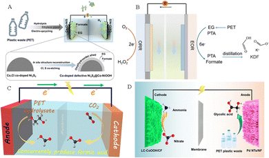 | ||
| Fig. 6 (A) H2 generation by seawater splitting coupled with plastic upgrading.52 Copyright 2023 Springer (B) Plastic waste electroreforming assisted water splitting.53 (C) CO2 reduction reaction.54 Copyright 2022 American Chemical Society. (D) Nitrate reduction reaction.55 Copyright 2023 American Chemical Society. | ||
3.1. Plastic electroreforming-assisted hydrogen production
Hydrogen is known as the “ultimate energy” to solve the energy crisis in the 21st century because of its high calorific value, cleanliness, and renewability. Compared to the traditional hydrogen production methods based on fossil fuels, utilizing renewable energy-driven electrochemical technology to obtain hydrogen by water splitting is considered to be the best way to achieve a “green hydrogen economy” in the future. In the process of hydrogen production by electrolysis of water, the cathodic hydrogen evolution reaction (HER) usually undergoes a 2-electron transfer process, followed by the Volmer–Heyrovsky step or the Volmer–Tafel step. And the anodic oxygen evolution reaction (OER) faces some challenges, such as high thermodynamic energy barriers, a slow kinetic process, and a low-value anodic product O2. Replacing the anode OER reaction with the plastic waste electrooxidation reaction can not only achieve green synthesis of high value-added chemicals, but also is expected to reduce oxidation overpotential, improve hydrogen production efficiency, and thus mitigate the challenges of high cost and low efficiency in green hydrogen production by electrolysis of water.The research on coupling PET plastic electrooxidation for hydrogen generation has been reported extensively. For example, Zhao and his team successfully achieved highly selective conversion of ethylene glycol in PET hydrolysate to formic acid product by using low-cost CuO nanowire electrocatalysts, while co-producing hydrogen gas at the cathode (Fig. 7A).37 Wang et al. established a HER||PET hydrolysate electrooxidation integrated system for co-generation of H2 and formate, and successfully achieved optimal 98.6% faradaic efficiency for H2 production coupled with the 95.6% faradaic efficiency for formate generation.38 Chen et al. used a bifunctional nickel cobalt nitride (Co–Ni3N/CC) nanosheet electrocatalyst to recycle PET waste with simultaneous hydrogen production. The results showed that the introduction of Co into the Co–Ni3N/CC electrocatalyst facilitates the redox behavior of Ni2+/Ni3+, which is beneficial for the oxidation of the active monomer EG at 1.15 V potential (Fig. 7B). In an integrated system containing PET hydrolysis products, the EG oxidation reaction (EGOR)||HER only requires a 1.46 V cell voltage to achieve a 50 mA cm−2 current density, which is 370 mV smaller than that required for traditional water splitting (Fig. 7C).41 Chen and his team constructed a system to co-produce H2 and high-value chemicals (Fig. 7D). After electrolysis and post-treatment of products, 5 g PET plastic waste can afford 4.21 g pure terephthalic acid, 2.28 g formic acid and 1.89 L H2 (Fig. 7E).39 Liu et al. proposed an innovative electroplating architecture by combining the EGOR with the HER by employing Pt–Ni(OH)2/NF as a bifunctional electrode, which can achieve high-value chemical production from the PET hydrolysate and H2 generation (Fig. 8A). And the EGOR||HER system only required a 0.68 V cell voltage to achieve 50 mA cm−2 current density, significantly superior to that over the Ni(OH)2/NF system (1.78 V) (Fig. 8B).56 Li et al. assembled a stacked membrane-free flow electrolyzer to upcycle PET waste bottles (Fig. 8C), and the result shows the stacked electrolyzer gives a current of ∼4.7 A at 1.4 V for EG oxidation (Fig. 8D), achieving a GA productivity of 471.2 mmol in 12.8 h (36.8 mmol h−1) and the cathodic H2 productivity of 985.6 mmol (77.0 mmol h−1) in 12.8 h (Fig. 8E). Furthermore, 19.4 g of EG (27.7 wt% yield) was obtained from 70 g of PET bottles after alkali treatment. After 23.3 h of electrolysis, EG could be further converted into 13.7 g of GA (81.6% yield) and 9.4 L of H2 (392.2 mmol) (Fig. 8F).57
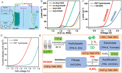 | ||
| Fig. 7 (A) Hybrid electrolysis for electroreforming of the PET hydrolysate and hydrogen evolution.37 Copyright 2022 American Chemical Society. (B) LSV curves of Co–Ni3N/CC and Ni3N/CC in an alkaline medium with and without addition of EG. (C) LSV curves of the coupled Co–Ni3N/CC in an alkaline medium or PET hydrolysate solution.41 Copyright 2022 Tsinghua University Press. (D) LSV curves of CuCo2O4 NWA/NF electrocatalysts in an alkaline electrolyte with and without PET.39 Copyright 2022 Royal Society of Chemistry. (E) Sketch map of the electro-reforming process and product separation.39 Copyright 2022 Royal Society of Chemistry. | ||
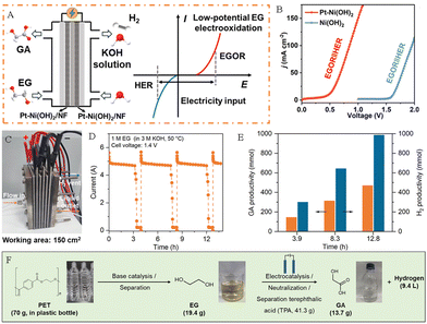 | ||
| Fig. 8 (A) Scheme of the EG flow cell and its electricity input mode. (B) LSV curves of Ni(OH)2/NF and Pt–Ni(OH)2/NF for PET hydrolysate oxidation.56 Copyright 2024 American Chemical Society. (C) Photograph and sketch map of the electrolyzer with three unit cells. (D) I–t curve of Au/Ni(OH)2 at 1.4 V in an alkaline medium with EG in the stacked electrolyzer. (E) The corresponding H2 and GA productivity at the counterpart Ni cathode at 1.4 V in an alkaline medium with EG. (F) Schematic diagram of electrocatalytic modification process for PET waste plastic bottles.57 Copyright 2023 American Chemical Society. | ||
3.2. Plastic electroreforming coupled with the CO2 reduction reaction
Carbon dioxide (CO2) is a colorless and odorless gas. The emission of a large amount of CO2 has aggravated the greenhouse effect, resulting in a rise in global temperatures and sea level, thus it is urgent to suppress the massive emissions of CO2 and to accelerate the utilization and conversion of CO2. The electrocatalytic CO2 reduction reaction (CO2RR) is an important cathodic reaction that has been proved to be a promising pathway for converting CO2 into fuels and valuable chemicals. The CO2RR is carried out at room temperature and atmospheric pressure, and the electricity can be directly obtained from renewable energy sources such as wind energy, solar energy, tidal energy and geothermal energy. Thus, electroreduction of CO2 is an efficient energy storage method to convert green energy into chemical energy. Previous studies have shown that EG derived from the PET plastic wastes can be selectively upgraded to HCOOH by electrooxidation.41 Meanwhile, the CO2RR can also convert CO2 into HCOOH.58–60 Therefore, it is feasible to integrate the cathodic CO2RR with the anodic PET oxidation reaction (POR) to generate HCOOH on both electrodes simultaneously. This dual waste (PET and CO2) electroreforming system for producing HCOOH not only achieves the rational recovery of carbon resources, but also reduces environmental pollution.Boukherroub's group constructed CuCoO@rGO and bismuth oxide carbonate loaded on rGO (BOC@rGO) electrocatalysts.61 Electrochemical studies have shown that CuCoO@rGO and BOC@rGO displayed outstanding activity for anodic electrooxidation of PET hydrolysate (Fig. 9A) and cathodic electroreduction of CO2 (Fig. 9B), respectively. Wherein, CuCoO@rGO displays a high FE of 85.7% toward FA production at 1.5 V, and the BOC@rGO electrode also exhibits a remarkable FE of 97.4% for FA production at −0.8 V. Compared with the CO2RR||OER system (2.13 V @10 mA cm−2), the CO2RR||POR system only required a 1.9 V cell voltage to attain 10 mA cm−2 (Fig. 9C) and the Faraday efficiency of HCOOH (FEHCOOH) was as high as 151.8% (Fig. 9D). This study not only efficiently reduces energy consumption, but also converts PET plastics and CO2 wastes into the same product formic acid, avoiding costly product separation. The spinel NiCo2O4 and tin dioxide (SnO2) nanosheets were prepared and employed as the electrocatalysts for anodic PET hydrolysate oxidation and the cathodic CO2RR, respectively.54 The experimental results showed that the spinel NiCo2O4 electrode exhibits a FE of 90% for FA production, indicating superior selectivity toward FA by the electrooxidation of PET hydrolysate. Moreover, the SnO2/CC electrode also possesses good selectivity with a FE of 82 ± 2% for FA generation by electroreduction of CO2. By coupling the cathodic CO2 reduction reaction with the anodic PET hydrolysis oxidation reaction, the assembled electrolyzer exhibits excellent activity, which only requires 1.55 V cell voltage to drive the reaction (Fig. 9E). Furthermore, the FE of HCOOH can reach 155% at a 1.90 V cell voltage (Fig. 9F).
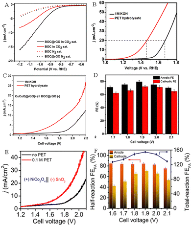 | ||
| Fig. 9 (A) Polarization curves of BOC and BOC@rGO electrocatalysts for the CO2 RR and HER. (B) Polarization curves of CuCoO@rGO in an alkaline medium with or without PET hydrolysate. (C) Polarization curves of CuCoO@rGO‖BOC@rGO in an alkaline medium with or without PET hydrolysate. (D) FEHCOOH at different applied cell voltages.61 Copyright 2023 The Royal Society of Chemistry. (E) Polarization curves of SnO2||NiCo2O4 in an alkaline medium with and without PET hydrolysate. (F) FEHCOOH at different potentials.54 Copyright 2022 American Chemical Society. | ||
Jiang et al. successfully synthesized oxygen-vacancy-rich Ni(OH)2–VO nanosheets and Bi/Bi2O3 nanoparticles by using PET derivatives (Fig. 10A–I), and used them as efficient electrocatalysts for anodic PET electrooxidation and the cathodic CO2 RR, respectively, to cogenerate HCOOH.62 The experimental results indicated that the Ni(OH)2–VO electrode exhibited excellent electrolytic activity for PET electrooxidation, which only needs 1.6 V to achieve ∼300 mA cm−2 (Fig. 11A). The FEHCOOH remained ∼86% and the yield was as high as 1.6 mmol h−1 cm−2 when 1.6 V was applied (Fig. 11B). In addition, the Ni(OH)2–VO electrode displayed outstanding stability for PET electrooxidation. As depicted in Fig. 11C, the changes in current density and passed charge remain similar over repeated cycles. The excellent electrocatalytic activity of Ni(OH)2–VO can be attributed to its abundant oxygen vacancies, which contribute to the formation of Ni3+ species and facilitate the subsequent dehydrogenation and C–C bond cleavage processes. Compared with pure Bi, the Bi/Bi2O3 nanoparticles display a better electrocatalytic activity towards the CO2RR (Fig. 11D) and FEHCOOH is over 90% in the voltage range of −0.6 to −1.4 V (Fig. 11E). It is worth noting that the FEHCOOH of the Bi/Bi2O3 heterostructure still exceeds 90% after a long-term reaction for more than 20![[thin space (1/6-em)]](https://www.rsc.org/images/entities/char_2009.gif) 000 s at 172 mA cm−2 current density (Fig. 11F). As presented in Fig. 11G, Jiang et al. assembled an electrolyzer powered by solar energy, in which HCOOH can be generated simultaneously on both sides of the electrodes. This electrolyzer exhibits excellent activity and stability, as well as high overall FEHCOOH production (Fig. 11H–J).62
000 s at 172 mA cm−2 current density (Fig. 11F). As presented in Fig. 11G, Jiang et al. assembled an electrolyzer powered by solar energy, in which HCOOH can be generated simultaneously on both sides of the electrodes. This electrolyzer exhibits excellent activity and stability, as well as high overall FEHCOOH production (Fig. 11H–J).62
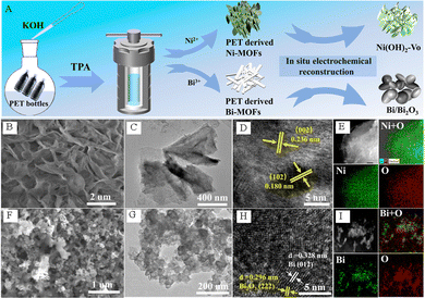 | ||
| Fig. 10 (A) Schematic diagram of the synthesis method of PET-derived oxygen-vacancy-rich Ni(OH)2–VO nanosheets and Bi/Bi2O3 nanoparticles. (B) SEM, (C) TEM, (D) HRTEM image and (E) EDS map of the Ni-MOFs-P after electrochemical reconstruction. (F) SEM, (G) TEM, (H) HRTEM image and (I) EDS map of Bi-MOFs-P after electrochemical reconstruction.62 Copyright 2023 American Chemical Society. | ||
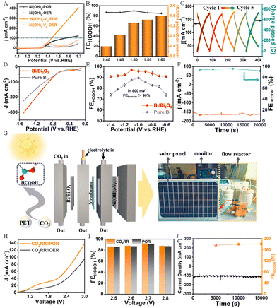 | ||
| Fig. 11 (A) LSV curves of Ni(OH)2–VO and Ni(OH)2 nanosheets in 1M KOH solution with or without PET. (B) The FEHCOOH and the production of HCOOH at different potentials. (C) Diagram of changes in current density and accumulated charges. (D) LSV curves of Bi/Bi2O3 electrocatalysts and pure Bi for the CO2 RR. (E) The FEHCOOH at different potentials for the CO2 RR. (F) The long-term durability test for CO2 RR over Bi/Bi2O3 electrocatalysts. (G) Schematic illustration of the electrolyzer powered by solar energy. (H) Polarization curves of CO2 RR||POR and CO2 RR||OER. (I) The corresponding FEHCOOH at different potentials for CO2 RR||POR. (J) The durability test for CO2 RR||POR.62 Copyright 2023 American Chemical Society. | ||
Besides PET plastic electrooxidation coupled with CO2 reduction, Zhang et al. coupled anodic PLA plastic waste electrooxidation with cathodic CO2 reduction to cogenerate formic acid, and achieved a high efficiency (95.2% for acetate and 94.8% for formate) by using a Bi-based electrocatalyst.33
3.3. Plastic electroreforming coupled with the oxygen reduction reaction
Hydrogen peroxide (H2O2), as an environmentally friendly oxidizer, is widely used in fields such as medical, textile, pesticide, papermaking, electronics and so on.63 At present, the anthraquinone method is employed for industrial production of H2O2, but this process involves multiple steps and complex operations, consumes high energy, and generates a large amount of organic waste, seriously polluting the environment. At the same time, the instability of H2O2 (e.g., self-detonation under enrichment conditions) also poses safety issues for transportation and storage.64 The oxygen reduction reaction (ORR) can be carried out through the two-electron (2e−) pathway to form HO2− (in alkaline media) or H2O2 (in acidic media) substances, and the 2e− pathway is composed of two coupled electron and proton transfers together with one intermediate (HOO*). The production method of H2O2via the ORR has the advantages of mild operating conditions, abundant oxygen feedstock, low voltage, high product selectivity and yield. Compared to the anthraquinone process, the electrocatalytic ORR without any hazardous byproducts is considered to be an ideal way for green synthesis of H2O2.65The electrosynthesis system combining the electrooxidation reaction of waste plastics with the ORR conversion to form H2O2 not only helps to reshape the life cycle of plastics and alleviate the plastic crisis, but can also solve the high energy consumption problem currently faced by the H2O2 electrosynthesis. Qiu's team designed Ni1Mn1-MOF-Se/NF and B/N-onion carbon loaded on the gas diffusion electrode to catalyze electrooxidation of ethylene glycol derived from the PET plastic waste and the ORR-to-H2O2 conversion with Faraday efficiencies of 93.0% (formic acid) (Fig. 12A–C) and 97.5% (H2O2) (Fig. 12D–E), respectively.53 They proposed an electrochemical synthesis scheme of coupling the conversion of ORR-to-H2O2 with the upgraded recycling of PET plastic wastes (Fig. 12G). As depicted in Fig. 12F, the electrolysis system successfully operated at a 0.927 V cell voltage for attaining 400 mA cm−2 current density, surpassing those of all reported H2O2 electrochemical synthesis systems. The chronoamperometry results show that the ORR||EOR electrosynthesis system exhibits excellent durability, indicating the high potential for industrial applications (Fig. 12I). The technical–economic evaluation highlights that the gross profit of the ORR||EOR system is higher than those of HER||PET and ORR||OER configurations (Fig. 12H). This work affords an energy-saving method for the electrosynthesis of H2O2 and other value-added chemicals.
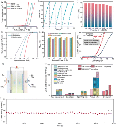 | ||
| Fig. 12 (A) Polarization curves of different electrodes in an alkaline medium with EG. (B) Charge–time curves of Ni1Mn1-MOF-Se/NF for the EOR. (C) FEHCOOH of Ni1Mn1-MOF-Se/NF under different voltages. (D) Polarization curves of different catalysts for the ORR. (E) FEH2O2 of B/N-onion carbon under different voltages. (F) Polarization curves of the ORR||OER system and the ORR||EOR electrosynthesis system. (G) Schematic diagram of the ORR||EOR system. (H) Evaluation of economic indicators for different systems. (I) Durability evaluating of the ORR||EOR system at 0.7 V.53 Copyright 2023 Nature Research. | ||
Liu et al. combined the EGOR with the ORR to construct a direct EG fuel cell by using the Pt–Ni(OH)2/NF electrodes as both the anode and cathode (Fig. 13A).56 The polarization and power-density curves of the EG fuel cell are presented in Fig. 13B, revealing a maximum power density of 4.20 mW cm−2, surpassing that of Pt/C/NF (2.21 mW cm−2). Zhang group's prepared oxygen-coordinated Fe single atoms (SAs) and atomic clusters (ACs) anchored on bacterial cellulose-derived carbon (BCC) (FeSAs/ACs-BCC) electrocatalysts and used them for the ORR to generate H2O2. In addition, they further combined the in situ produced H2O2 with the electro-Fenton process to achieve the upgrading of EG derived from PET wastes into high-valued FA (Fig. 13C).66
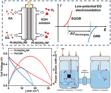 | ||
| Fig. 13 (A) Sketch map of the direct EG fuel and its electricity output mode. (B) The polarization and power-density curves for the direct EG fuel.56 Copyright 2024 American Chemical Society. (C) Sketch map of the valorization of ethylene glycol (EG) by the electro-Fenton process at the FeSAs/ACs-BCC/GF cathode.66 Copyright 2023 Wiley-VCH GmbH. | ||
3.4. Plastic electroreforming coupled with the nitrate reduction reaction
Ammonia (NH3) is a commodity chemical in the modern chemical industry and an important pillar of the economy.67 Therefore, the production of ammonia is very crucial. Under the historical background of “carbon neutrality” and “carbon peak”, NH3 can not only serve as a clean fuel, but is also considered to be a highly competitive “green hydrogen” storage and transportation carrier.68 At present, the traditional Haber–Bosch route for synthesizing ammonia needs high temperature (350–450 °C) and high pressure (100–200 bar), and not only consumes energy intensively, but also releases a large amount of CO2.69 In order to avoid high energy consumption and carbon emissions, it has become more urgent to explore other synthetic ammonia pathways under mild conditions.Nitrate (NO3−) is a toxic chemical that is widely present in agricultural and industrial wastewater. NO3− not only destroys the ecological balance of water, but also causes diseases and threatens human health.70 From the perspective of environment and energy, it is a strategy of “killing two birds with one stone” to convert NO3− in wastewater into high-valued NO3 driven by green electricity. Therefore, electrocatalytic NO3− reduction reaction (NO3−RR) to synthesize valuable NH3 is considered as a charming and green alternative to the Haber–Bosch method.71,72 Similar to the electrolytic cell assembled by the CO2RR coupled with the PET oxidation reaction (POR), the NO3−RR can also be combined with plastic waste electrooxidation. Specifically, the anode uses plastic hydrolysate as an electrolyte for the electrooxidation recovery of plastic wastes, and the cathode uses industrial wastewater containing nitric acid as an electrolyte to electrochemically reduce pollutants. The constructed plastic hydrolysate/nitrate co-electrolysis system can not only solve the problem of nitrate and plastic pollution, avoid the separation of industrial pollution, but also simultaneously produce high-valued NH3 and FA or glycolic acid.
For example, Xu et al. constructed Ru-incorporated Co-based MOF nanosheets loaded on nickel foam (CoRu-MOF/NF) as a dual-functional precatalyst.73 As depicted in Fig. 14A, the CoRu-MOF/NF precatalyst was in situ reconstructed to form Ru–CoOOH/NF and Ru–Co(OH)2/NF through electrocatalytic operation, which can be used as electrocatalysts for anodic PET hydrolysate oxidation and the cathodic NO3−RR, respectively. The Ru–Co(OH)2/NF electrocatalyst exhibited higher current density compared to that for the pure HER reaction (Fig. 14B). And the conversion efficiency of NO3−–N reached 98.91% at −0.3 V (Fig. 14C), while the yield rate and FE were 0.244 mmol h−1 cm−2 and 94.3%, respectively (Fig. 14D). In addition, the Ru–CoOOH/NF electrode exhibited excellent activity and stability for PET hydrolysate oxidation to generate HCOOH (Fig. 14E and F). Based on the outstanding activity for the NO3−RR and POR, the electrocatalytic system integrating NO3−RR and POR activities displays a lower potential (1.53 V) at 50 mA cm−2 current density compared to that of the NO3−RR||OER electrolyzer (1.79 V) and can be used to achieve simultaneous production of NH3 and formate (Fig. 14G).
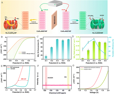 | ||
| Fig. 14 (A) Sketch map of the electrocatalytic system integrating the NO3−RR and POR activities. (B) Polarization curves of Ru–Co(OH)2/NF in an alkaline medium with or without 200 ppm KNO3–N. (C) NO3−–N conversion efficiency and (D) yield rates of NH3 and FEHCOOH at various potentials. (E) Polarization curves of Ru–CoOOH/NF in an alkaline medium with or without PET hydrolysate. (F) 13C NMR spectrum of PET hydrolysate oxidation products. (G) Polarization curves of the NO3−RR||OER system and the NO3−RR||POR system.73 Copyright 2023 American Chemical Society. | ||
Xu’ group also in situ grew Pd nanothorns (Pd NTs/NF) and low-crystalline CoOOH (LC-CoOOH/CF) on the nickel foam substrate, and used them as anode and cathode electrocatalysts for PET electrooxidation and nitrate reduction, respectively.55 The electrochemical experimental results showed that the LC-CoOOH/CF electrode showed excellent electrocatalytic NO3−RR performance (Fig. 15A) and exhibited the optimum rNH3 (0.246 mmol h−1 cm−2) (Fig. 15B) and NH3 FE (97.38 ± 1.0%) (Fig. 15C) in the voltage range of −0.25 to −0.45 V vs. RHE, which are superior to those of highly crystalline CoOOH loaded on CF (HC-CoOOH/CF) (rNH3 (0.099 mmol h−1 cm−2) and NH3 FE (78.42 ± 7.2%)), indicating that the introduction of a partial amorphous phase to construct a low-crystalline catalyst with a crystalline–amorphous heterogeneous structure can effectively improve the NO3RR performance. In addition, Pd nanoparticles grown on nickel foam (Pd NPs/NF) present similar electrooxidation properties to the Pd NTs/NF electrode in the electrooxidation process of EG to formate, but the electrooxidation peak of EG to GA is weak, suggesting that the nanothorn structure is important for the electrooxidation of EG to GA. The nanothorn structure provides a high-curvature tip to the Pd NTs/NF electrode, increasing the concentration of local OH− in the active sites, which is beneficial for accelerating the EG electrooxidation process (Fig. 15D). And EG can be oxidized to carboxyl groups to form GA at a low voltage range (0.6–1.0 V) (Fig. 15E), and to form formate at a high voltage (≥1.34 V) (Fig. 15F). Compared with the NO3−RR||OER electrolyzer (onset voltage of 1.4 V), the NO3−RR||POR electrolyzer (onset voltage of 0.5 V) requires much lower energy consumption (Fig. 15G–I).
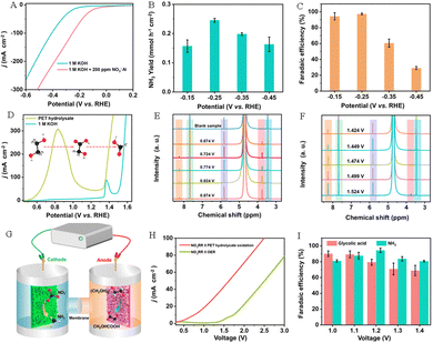 | ||
| Fig. 15 (A) Polarization curves of LC-CoOOH/CF in an alkaline medium with or without 200 ppm KNO3-N. NH3 yield rates (B) and FE(C) for LC-CoOOH/CF at different voltages. (D) Polarization curves of Pd NTs/NF in an alkaline medium with or without PET hydrolysate. 1H NMR spectra of PET hydrolysate and PET hydrolysate oxidation products over Pd NTs/NF in a (E) low voltage range and (F) high voltage range. (G) Schematic diagram of the NO3−RR||POR electrolyzer. (H) Polarization curves of the NO3−RR||OER and the NO3−RR||POR electrolyzer. (I) FE of NH3 and GA with different voltages.55 Copyright 2023 American Chemical Society. | ||
4. Conclusions and outlooks
In conclusion, electroreforming of plastic wastes is a sustainable and promising catalytic method that can replace the anodic OER in traditional water splitting. This article has introduced the electrooxidation reaction mechanisms of different plastic wastes (e.g. PLA, PET, PE, PBT, etc.), and overviewed the progress of coupling the electrooxidation reaction of plastic wastes with the HER, ORR, CO2RR and NO3RR, including the preparation and performance of electrocatalysts.Although tremendous progress has been made in converting plastic wastes into valuable commodities electrocatalytically in recent years, there are still many areas that need further improvement and development in direct production of high-value chemicals from plastic wastes through electrocatalysis.
4.1. Hydrolysis of plastic wastes
At present, electrocatalytic oxidation process of plastic wastes involves first dissolving the plastics into small molecule monomers, and then further converting them into valuable chemicals with added value through electrochemical oxidation. However, the low solubility of plastic wastes in electrolytes makes it difficult to depolymerize them into large amounts of small molecule monomers, which will result in the low current density for electrooxidation, further hindering its development. Improving the solubility of plastic wastes is crucial for realizing industrialized electrical recycling of plastic wastes. Therefore, new pre-treatment methods that are compatible with the following electroreforming process are highly desirable. For example, one may depolymerize waste plastics under low temperature and high pressure conditions with addition of suitable solvents (such as ethanol, methanol, etc.), utilizing the alcohol-alkali combined depolymerization mechanism to increase the solubility of waste plastics in the electrolyte. Ethanol or methanol in the solution will also undergo electrochemical oxidation, which can eliminate the separation cost of different solvents. Additionally, biological and electrochemical catalysts can be coupled to assemble into integrated catalysts, which can not only enhance the hydrolysis of waste plastics using biological enzyme depolymerization, but also convert waste plastics into high-value chemicals under mild conditions.4.2. In situ characterization techniques
Exploring the catalytic conversion mechanism of plastics wastes is crucial for their efficient recycling. Electrochemical in situ characterization technology is a very important technique that can be used to study the mechanisms and kinetic processes of electrochemical reactions. For example, in situ nuclear magnetic resonance spectroscopy technology can be used to monitor liquid products during the reaction process in real time, thereby analyzing the activity, selectivity, and durability of electrodes. And in situ X-ray absorption near edge structure (XANES) can be applied to identify changes in catalyst sites under reaction conditions, such as chemical states and atomic structures. At present, most of the plastic electrocatalytic products are tested after a certain reaction duration, and the reaction mechanism is inferred from the products. Therefore, introducing in situ characterization techniques in the process of plastic electroreforming conversion can provide important information and a deeper understanding of the catalytic mechanism of plastics.4.3. Synergistic catalysis for efficient recycling of plastics
Integrating multiple energy sources in the plastic recycling process may become a potential method to reduce energy consumption or improve current efficiency. For example, the overall cost of plastic electrocatalytic recycling can be reduced when the electricity comes from wind energy, tidal energy, solar energy in the electrocatalytic process of plastics. In addition, introducing a light source in the electrocatalytic process to achieve plastic photocatalytic conversion in the photoelectrochemical process could largely enrich the chemistry and potential valuable products. An external magnetic field can be introduced to enhance activity of electrocatalysts, particularly those with magnetic properties such as Ni, Co, Fe-based catalysts. The synergistic effect generated by the combination of optoelectronics and magnetism may improve the overall energy efficiency and potentially generate more value-added products.4.4. Pre-separation of mixed waste plastics
In previous studies, waste plastics with rich ester groups in their macromolecular structures (such as PET and PLA) were used. These polyester can be easily hydrolyzed into small molecule monomers and further electrocatalytically oxidized into high-value chemicals. However, besides these simple polyester plastics, real plastic wastes typically contain many auxiliary components, including plasticizers, fillers, lubricants, colorants and so on. During the electrochemical treatment process, these complex auxiliary substances can seriously affect the electrochemical oxidation efficiency and product purity. Therefore, it is necessary to develop a step-by-step approach based on the properties of each auxiliary component before the electrooxidation of plastic wastes to obtain a feedstock with one dominant component. This is apparently very challenging, yet necessary if very valuable products are targeted.4.5. Development of electrocatalysts and reactors
Developing innovative reactors and high-activity, highly-selectivity, and stable electrocatalysts suitable for industrial applications is crucial to the future development of plastic electroreforming technology. Most current research focused on laboratory testing of simple plastic wastes or clean plastics, which are very different from practical unsorted plastic waste mixtures. At the industrial scale, the preparation of catalysts, reactor parameters, and electrolysis conditions are all subject to certain limitations arising from consideration of cost and scalability, and then the selectivity and conversion rate of electrooxidation products could be affected. In addition, plasticizers, colorants and other substances in real plastic wastes may adsorb on the surface of electrocatalysts, occupying the electrocatalytically active sites and inhibiting the progress of electrocatalytic oxidation reactions, resulting in poor activity and stability of the electrocatalysts. Therefore, it is important to develop suitable reactors and electrocatalysts with low-cost, high activity, and excellent stability for large-scale implementation.Author contributions
Ying Li: investigation, methodology, and writing – original draft. Lang Liu: supervision, writing – review and editing, and funding acquisition. Li Quan Lee: investigation and formal analysis. Hong Li: funding acquisition and writing – review and editing.Data availability
The data supporting this study's findings are available from the corresponding author upon reasonable request.Conflicts of interest
There are no conflicts to declare.Acknowledgements
This work was supported by Ministry of Education Singapore (Award No: RG153/23) and the Agence Nationale de la Recherche (ANR) in the PEECFUEL project (ANR-23-CE05-0026) and projects of Natural Science Foundation of China (52074212).Notes and references
- F. Zhang, Y. Zhao, D. Wang, M. Yan, J. Zhang, P. Zhang, T. Ding, L. Chen and C. Chen, J. Cleaner Prod., 2021, 282, 124523 CrossRef CAS
.
- W. C. Li, H. F. Tse and L. Fok, Sci. Total Environ., 2016, 566–567, 333–349 CrossRef CAS PubMed
.
- T. R. Praveenkumar, M. Sekar, R. R. Pasupuleti, B. Gavurová, G. Arun Kumar and M. Vignesh Kumar, Fuel, 2024, 357, 129379 CrossRef CAS
.
- D. Sajwan, A. Sharma, M. Sharma and V. Krishnan, ACS Catal., 2024, 14, 4865–4926 CrossRef CAS
.
- M. Kiendrebeogo, M. R. Karimi Estahbanati, A. Khosravanipour Mostafazadeh, P. Drogui and R. D. Tyagi, Environ. Pollut., 2021, 269, 116168 CrossRef CAS
.
- D. Cudjoe and H. Wang, Fuel Process. Technol., 2022, 237, 107470 CrossRef
.
- Q. Hu, Z. Zhang, D. He, J. Wu, J. Ding, Q. Chen, X. Jiao and Y. Xie, J. Am. Chem. Soc., 2024, 146, 16950–16962 CrossRef CAS
.
- H. A. Leslie, M. J. M. van Velzen, S. H. Brandsma, A. D. Vethaak, J. J. Garcia-Vallejo and M. H. Lamoree, Environ. Int., 2022, 163, 107199 CrossRef CAS PubMed
.
- A. Ragusa, V. Notarstefano, A. Svelato, A. Belloni, G. Gioacchini, C. Blondeel, E. Zucchelli, C. De Luca, S. D'Avino, A. Gulotta, O. Carnevali and E. Giorgini, Polymers, 2022, 14, 2700 CrossRef CAS PubMed
.
- Z. O. G. Schyns and M. P. Shaver, Macromol. Rapid Commun., 2021, 42, e2000415 CrossRef PubMed
.
- K. Ragaert, L. Delva and K. Van Geem, Waste Manage., 2017, 69, 24–58 CrossRef CAS
.
- A. Rahimi and J. M. García, Nat. Rev. Chem., 2017, 1, 0046 CrossRef
.
- N. George and T. Kurian, Ind. Eng. Chem. Res., 2014, 53, 14185–14198 CrossRef CAS
.
- A. A. Shah, F. Hasan, A. Hameed and S. Ahmed, Biotechnol. Adv., 2008, 26, 246–265 CrossRef CAS
.
- X. Liu, Z. Fang, X. Teng, Y. Niu, S. Gong, W. Chen, T. J. Meyer and Z. Chen, J. Energy Chem., 2022, 72, 432–441 CrossRef CAS
.
- Y. Li, L. Q. Lee, Z. G. Yu, H. Zhao, Y.-W. Zhang, P. Gao and H. Li, Sustain. Energy Fuels, 2022, 6, 4916–4924 RSC
.
- T. Zhang, X. Li, J. Wang, Y. Miao, T. Wang, X. Qian and Y. Zhao, J. Hazard. Mater., 2023, 450, 131054 CrossRef CAS
.
- J. Cho, B. Kim, T. Kwon, K. Lee and S.-I. Choi, Green Chem., 2023, 25, 8444–8458 RSC
.
- J. Li, H. P. Ma, G. Zhao, G. Huang, W. Sun and C. Peng, ChemSusChem, 2024, 17, e202301352 CrossRef CAS
.
- Y. Ma, Y. Zhang, W. Yuan, M. Du, S. Kang and B. Qiu, EES Catal., 2023, 1, 892–920 RSC
.
- S. Ügdüler, K. M. Van Geem, R. Denolf, M. Roosen, N. Mys, K. Ragaert and S. De Meester, Green Chem., 2020, 22, 5376–5394 RSC
.
- S. Kumagai, S. Hirahashi, G. Grause, T. Kameda, H. Toyoda and T. Yoshioka, J. Mater. Cycles Waste Manage., 2017, 20, 439–449 CrossRef
.
- S. D. Mancini and M. Zanin, Polym.-Plast. Technol., 2007, 46, 135–144 CrossRef CAS
.
- S. Mishra, A. S. Goje and V. S. Zope, Polym. React. Eng., 2017, 11, 79–99 CrossRef
.
- S. D. M. A. M. Zanin, Prog. Rubber, Plast. Recycl. Technol., 2004, 20, 117–132 CrossRef
.
- M. T. Zumstein, D. Rechsteiner, N. Roduner, V. Perz, D. Ribitsch, G. M. Guebitz, H. E. Kohler, K. McNeill and M. Sander, Environ. Sci. Technol., 2017, 51, 7476–7485 CrossRef CAS
.
- A. Borchers and T. Pieler, Genes, 2010, 1, 413–426 CrossRef CAS
.
- X. Hu, D. Ma, G. Zhang, M. Ling, Q. Hu, K. Liang, J. Lu and Y. Zheng, Carbon Resour. Convers., 2023, 6, 215–228 CrossRef CAS
.
- Z. Jiang, Y. Liang, F. Guo, Y. Wang, R. Li, A. Tang, Y. Tu, X. Zhang, J. Wang, S. Li and L. Kong, ChemSusChem, 2024, e202400129 CrossRef CAS
.
- C. S. Bhogle and A. B. Pandit, Indian Chem. Eng., 2017, 60, 122–140 CrossRef
.
- Y. Li, L. Q. Lee, H. Zhao, Y. Zhao, P. Gao and H. Li, J. Mater. Chem. A, 2024, 12, 2121–2128 RSC
.
- H. Yu, Y. Wang, L. Chen, C. Wei, T. Mu and Z. Xue, Green Chem., 2023, 25, 7807–7816 RSC
.
- B. Lan, Y. Chen, N. Xiao, N. Liu, C. Juan, C. Xia and F. Zhang, J. Energy Chem., 2024, 97, 575–584 CrossRef CAS
.
- Y. Chen, X. Zhang, C. Liu, W. Xue, M. Wei, S. Hu, Q. Jiang, T. Zheng, X. Li and C. Xia, ACS Appl. Mater. Interfaces, 2024, 16, 20570–20576 CAS
.
- Y. Li, Y. Zhao, H. Zhao, Z. Wang, H. Li and P. Gao, J. Mater. Chem. A, 2022, 10, 20446–20452 RSC
.
- Y. Ma, X. Guo, M. Du, S. Kang, W. Dong, V. Nicolosi, Z. Cui, Y. Zhang and B. Qiu, Green Chem., 2024, 26, 3995–4004 RSC
.
- J. Wang, X. Li, T. Zhang, Y. Chen, T. Wang and Y. Zhao, J. Phys. Chem. Lett., 2022, 13, 622–627 CrossRef CAS PubMed
.
- H. Zhang, Y. Wang, X. Li, K. Deng, H. Yu, Y. Xu, H. Wang, Z. Wang and L. Wang, Appl. Catal., B, 2024, 340, 123236 CrossRef CAS
.
- X. G. Fulai Liu, R. Shi, E. C. M. Tse and Y. Chen, Green Chem., 2022, 24, 6571–6577 RSC
.
- H. Kang, D. He, X. Yan, B. Dao, N. B. Williams, G. I. Elliott, D. Streater, J. Nyakuchena, J. Huang, X. Pan, X. Xiao and J. Gu, ACS Catal., 2024, 14, 5314–5325 CrossRef CAS PubMed
.
- X. Liu, Z. Fang, D. Xiong, S. Gong, Y. Niu, W. Chen and Z. Chen, Nano Res., 2023, 16, 4625–4633 CrossRef CAS
.
- M. Song, Y. Wu, Z. Zhao, M. Zheng, C. Wang and J. Lu, Adv. Mater., 2024, 36, e2403234 CrossRef PubMed
.
- D. Si, B. Xiong, L. Chen and J. Shi, Chem. Catal., 2021, 1, 941–955 CrossRef CAS
.
- H. Yan, S. Yao, J. Wang, S. Zhao, Y. Sun, M. Liu, X. Zhou, G. Zhang, X. Jin, X. Feng, Y. Liu, X. Chen, D. Chen and C. Yang, Appl. Catal., B, 2021, 284, 119803 CrossRef CAS
.
- F. Liu, X. Gao, R. Shi, Z. Guo, E. C. M. Tse and Y. Chen, Angew. Chem., Int. Ed., 2023, 62, e202300094 CrossRef CAS PubMed
.
- M. Du, Y. Zhang, S. Kang, C. Xu, Y. Ma, L. Cai, Y. Zhu, Y. Chai and B. Qiu, Small, 2023, 19, e2303693 CrossRef PubMed
.
- C. M. Pichler, S. Bhattacharjee, M. Rahaman, T. Uekert and E. Reisner, ACS Catal., 2021, 11, 9159–9167 CrossRef CAS
.
- L. Ren, S. Yang, J. Wang, T. Zhang, X. Li, T. Wang and Y. Zhao, React. Chem. Eng., 2023, 8, 1937–1942 RSC
.
- C. Xiao, W. R. Leow, L. Chen, Y. Li and C. Li, Electron, 2023, 1, e14 CrossRef
.
- X. Liu, J. Wang, Z. Fang, S. Gong, D. Xiong, W. Chen, D. Wu and Z. Chen, Appl. Catal., B, 2023, 334, 122870 CrossRef CAS
.
- K. Liu, X. Gao, C. X. Liu, R. Shi, E. C. M. Tse, F. Liu and Y. Chen, Adv. Energy Mater., 2024, 14, 2304065 CrossRef CAS
.
- Z. Chen, R. Zheng, T. Bao, T. Ma, W. Wei, Y. Shen and B. J. Ni, Nano-micro Lett., 2023, 15, 210 CrossRef CAS PubMed
.
- J. Qi, Y. Du, Q. Yang, N. Jiang, J. Li, Y. Ma, Y. Ma, X. Zhao and J. Qiu, Nat. Commun., 2023, 14, 6263 CrossRef CAS PubMed
.
- J. Wang, X. Li, M. Wang, T. Zhang, X. Chai, J. Lu, T. Wang, Y. Zhao and D. Ma, ACS Catal., 2022, 12, 6722–6728 CrossRef CAS
.
- T. Ren, Z. Duan, H. Wang, H. Yu, K. Deng, Z. Wang, H. Wang, L. Wang and Y. Xu, ACS Catal., 2023, 13, 10394–10404 CrossRef CAS
.
- X. Liu, X. He, D. Xiong, G. Wang, Z. Tu, D. Wu, J. Wang, J. Gu and Z. Chen, ACS Catal., 2024, 14, 5366–5376 CrossRef CAS
.
- Y. Yan, H. Zhou, S. M. Xu, J. Yang, P. Hao, X. Cai, Y. Ren, M. Xu, X. Kong, M. Shao, Z. Li and H. Duan, J. Am. Chem. Soc., 2023, 145, 6144–6155 CrossRef CAS PubMed
.
- H. Shen, H. Jin, H. Li, H. Wang, J. Duan, Y. Jiao and S. Z. Qiao, Nat. Commun., 2023, 14, 2843 CrossRef CAS
.
- B. Chen, Y.-F. Jiang, H. Xiao and J. Li, ACS Catal., 2024, 14, 10510–10518 CrossRef CAS
.
- Y. Qiao, W. Lai, K. Huang, T. Yu, Q. Wang, L. Gao, Z. Yang, Z. Ma, T. Sun, M. Liu, C. Lian and H. Huang, ACS Catal., 2022, 12, 2357–2364 CrossRef CAS
.
- S. K. Kilaparthi, A. Addad, A. Barras, S. Szunerits and R. Boukherroub, J. Mater. Chem. A, 2023, 11, 26075–26085 RSC
.
- F. Ma, Z. Li, R. Hu, Z. Wang, J. Wang, J. Li, Y. Nie, Z. Zheng and X. Jiang, ACS Catal., 2023, 13, 14163–14172 CrossRef CAS
.
- P. Zhu, W. Feng, D. Zhao, P. Song, M. Li, X. Tan, T. Liu, S. Liu, W. Zhu, Z. Zhuang, J. Zhang and C. Chen, Angew. Chem., Int. Ed., 2023, 62, e202304488 CrossRef CAS PubMed
.
- Y. Wang, G. I. N. Waterhouse, L. Shang and T. Zhang, Adv. Energy Mater., 2020, 11, 2003323 CrossRef
.
- C. Kim, S. O. Park, S. K. Kwak, Z. Xia, G. Kim and L. Dai, Nat. Commun., 2023, 14, 5822 CrossRef CAS PubMed
.
- H. Xu, S. Zhang, X. Zhang, M. Xu, M. Han, L. R. Zheng, Y. Zhang, G. Wang, H. Zhang and H. Zhao, Angew. Chem., Int. Ed., 2023, 62, e202314414 CrossRef CAS
.
- W. He, J. Zhang, S. Dieckhofer, S. Varhade, A. C. Brix, A. Lielpetere, S. Seisel, J. R. C. Junqueira and W. Schuhmann, Nat. Commun., 2022, 13, 1129 CrossRef CAS
.
- J. Theerthagiri, J. Park, H. T. Das, N. Rahamathulla, E. S. F. Cardoso, A. P. Murthy, G. Maia, D. V. N. Vo and M. Y. Choi, Environ. Chem. Lett., 2022, 20, 2929–2949 CrossRef CAS
.
- Y. Yao, J. Wang, U. B. Shahid, M. Gu, H. Wang, H. Li and M. Shao, Electrochem. Energy Rev., 2020, 3, 239–270 CrossRef CAS
.
- X. Liu, P. V. Kumar, Q. Chen, L. Zhao, F. Ye, X. Ma, D. Liu, X. Chen, L. Dai and C. Hu, Appl. Catal., B, 2022, 316, 121618 CrossRef CAS
.
- Y. Liu, K. Liu, P. Wang, Z. Jin and P. Li, Carbon Neutrality, 2023, 2, 14 CrossRef
.
- H. Li, M. Tu, Y. Fang, T. Hao and B. Wang, ACS Appl. Nano Mater., 2023, 6, 18238–18246 CrossRef CAS
.
- T. Ren, Z. Yu, H. Yu, K. Deng, Z. Wang, X. Li, H. Wang, L. Wang and Y. Xu, ACS Nano, 2023, 17, 12422–12432 CrossRef CAS PubMed
.
| This journal is © The Royal Society of Chemistry 2025 |
