 Open Access Article
Creative Commons Attribution 3.0 Unported Licence
Recent progresses in the synthesis and strategic designs of sustainable carbon-based fibrous electrodes for flexible batteries
Susmi Anna
Thomas
 a,
Jayesh
Cherusseri
 *bc and
Deepthi N.
Rajendran
 *a
*a
aDepartment of Physics, Government College for Women (Affiliated to University of Kerala), Thiruvananthapuram, Kerala 695014, India. E-mail: deepthinrphysics@gmail.com
bResearch Centre for Nanomaterials and Energy Technology (RCNMET), School of Engineering and Technology, Sunway University, No. 5, Jalan Universiti, Bandar Sunway, 47500 Selangor Darul Ehsan, Malaysia. E-mail: drjayeshpuli@gmail.com
cSchool of Engineering and Technology, Sunway University, No. 5, Jalan Universiti, Bandar Sunway, 47500 Selangor Darul Ehsan, Malaysia
First published on 28th October 2024
Abstract
Electrochemical energy storage devices, such as rechargeable batteries and supercapacitors, have replaced conventional batteries and dielectric capacitors owing to their excellent charge storage abilities and other electrochemical performances. However, a major challenge exists in terms of their flexibility in application because most of the rechargeable batteries and supercapacitors available commercially are rigid and hence cannot be used in wearable electronic applications. The flexibility of the devices is mainly imparted by electrodes; hence, the preparation of electrodes is of utmost importance in determining their flexibility. During the fabrication of electrodes, electrode-active materials are coated over an electrically conducting substratum and it is further used as a current collector for the electrodes. The electrodes are flexible if the substratum used is flexible. In this respect, carbon fibers (CFs) have evolved as a suitable and sustainable substratum for the preparation of electrodes for rechargeable batteries to power flexible electronic devices. Micron-sized or nano-sized CFs are invariably used as substrata; hence, flexibility can easily be imparted to the devices assembled. This review outlines the development of rechargeable batteries manufactured from different electrode-active materials coated over this CF substratum. This article provides an in-depth insight into the preparation of flexible electrodes for rechargeable batteries, particularly for application in wearable electronics.
Sustainability spotlightWearable electronic devices necessitate high-energy, flexible energy storage devices. Flexible batteries with carbon-based fibrous electrodes have attracted attention as modern gadgetry owing to their high bendability and twistability. The development of sustainable batteries is of utmost importance to achieve the UN Sustainable Development Goal 7: Affordable and Clean Energy. Carbon-based flexible electrodes are highly sustainable materials for developing flexible batteries for next-generation wearable electronic devices. |
1. Introduction
Burgeoning urbanization and the steep growth of the global population play pivotal roles in energy scarcity. The depletion of fossil fuels has become not a matter of just discussion but a reality.1,2 Although the war between nations has already become a nightmare, sustainability is a long-term goal put forward for the betterment of human society. To resolve the non-availability of non-renewable energy sources, research has been directed towards renewable energy sources.3,4 Renewable energy conversion technologies, such as solar cells, wind turbines, and wave energy, have become the most popular choices. However, the intermittent nature of energy production has become an issue in delivering power on demand on a 24 × 7 basis. To eradicate this issue, electrochemical energy storage technologies have evolved. Electrochemical energy storage technologies have become popular owing to their high efficiency, compact device structure, portability, low cost and scalability. Among the various electrochemical energy storage technologies, rechargeable batteries and supercapacitors have become the most popular considering their excellent energy storage, scalability, efficiency, and long cycling life. Rechargeable batteries are a viable source of energy storage because of their high specific capacity, long cycling life and portability.5,6 Among the various electrochemical energy storage technologies, rechargeable batteries facilitate an efficient route for the management of power supply by storing electricity in the form of chemical energy with higher efficiency. Modern devices, such as electric vehicles, portable personal electronics, power tools and many other electronic devices, highly depend on rechargeable batteries, especially lithium-ion (Li-ion) batteries (LIBs) in the past. However, these LIBs have some disadvantages due to their increased cost for Li-based resources and their non-uniform geographical distribution. This introduced a new research route for post-Li battery technologies, such as metal-ion batteries (for example, sodium-ion (Na-ion) batteries (SIBs) and potassium-ion batteries), dual-ion batteries and other battery types, to overcome the challenges associated with LIBs.7 Thus, LIBs compete with the current demand for energy storage devices despite their high-performance characteristics. Hence, there is a huge demand for other classes of battery-type materials in energy storage devices. Batteries are selected according to their several features for specific purposes, such as portable electronics, grid storage, and home appliances, and requirements, such as required voltage, power density, energy density, cost, and cycle life.8 LIBs have a higher characteristic performance with reduced weight, and they are mostly suited for portable electronic devices, such as mobile phones.9,10 In addition, SIBs are best suited to applications, but their weight, price and environmental concerns have higher priority, such as grid storage, where batteries are used for long durations.11,12 These long-term applications need a higher degree of capacity in cheaper and less frequent recharging.Developing sustainable materials for rechargeable batteries has become highly demanding due to the versatility of modern electronic devices.13,14 Environmental acceptability is mandatory for all the newly emerging technologies and devices based on the Sustainable Development Goals (SDGs) put forward by the United Nations.15 The basic entity for any device is material; hence, developing a sustainable material for any device is the basic step. The salient features of materials, such as sustainability, recyclability, availability, and energy efficiency, play a crucial role in their wide acceptance. The case of emerging rechargeable batteries, such as post-LIBs, has mainly focused on non-Li electrodes.16 The reduction in cost, sustainability and material abundance is the most astonishing feature expected from a non-Li electrode for application in rechargeable batteries.17 A statistical analysis of research publications based on rechargeable batteries for the past 20 years is depicted in Fig. 1. From this statistical analysis, it is clear that rechargeable batteries have become of utmost interest to mankind due to their efficiency in competing with the current energy demand.
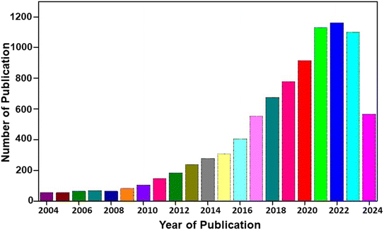 | ||
| Fig. 1 Statistical analysis of publications on rechargeable batteries for the past 20 years [source: Web of Science]. | ||
With recent developments in flexible and wearable electronic devices, flexibility has become the focus of research. In the case of modern energy storage technologies, the major parameter of their practical applications lies in their flexibility. Flexible electronics has been a highly flourished research area in the past decade with historical breakthroughs. It has been found that this flexible electronics field has wider applications in different aspects of human life, including wearable sensors for the monitoring of human behaviour patterns,18 flexible micro-mobile power in portable exoskeletons, implantable electronics in minimally invasive surgery/pathology diagnostic medical imaging,19 and remote-health monitoring.20 In addition, the synergistic combination of diverse flexible and wearable gadgetries showcases the utilization of flexible and wearable electrochemical energy storage devices, such as supercapacitors and batteries.21 The multifunctional applications in daily life and internet-of-things (IoTs)-based microelectronic devices necessitate flexible and safe electrochemical energy storage devices to power them. Developing flexible and wearable electrochemical energy storage devices requires flexible and wearable substrates to prepare electrodes for their manufacturing. The preparation of flexible substrates necessitates lightweight and good mechanical properties, along with good electrochemical properties.
The fabrication of flexible energy storage devices, namely rechargeable batteries, highly depends on the selection of suitable substrates. The modification of energy storage devices on flexible substrates has their application in IoT-based electronic devices. The fiber-based materials facilitate higher thermal conductivity, chemical stability and electrical conductivity. Carbon fiber (CF)-based materials are prominent among them, and they are applied as current collectors and active materials for energy storage devices. Depending on the graphitic character, CF microstructures can be completely graphitic, semi graphitic or non-graphitic. Directional orientation in these fiber-based materials, especially CF, holds a mesophase pitch precursor that introduces bonding of carbon–carbon conductive framework, which contains pristine CF along the carbonization procedure.22,23 CF has a higher content of graphite and can promote the insertion/extraction of Li-ion into/from the graphite, which acts as an anode for LIBs and provides higher capacity due to its high loading of graphite mass. CF-based electrodes are not only free-standing but also capable of the intercalation/deintercalation of cations/anions. When it is utilized as both a cathode and anode, CF-based materials can form a dual carbon CF battery. Material researchers and energy scientists have highly concentrated on the feasible application of these CF-based materials in rechargeable battery applications. A statistical analysis of the number of research publications on fiber-based rechargeable batteries for the past 10 years is illustrated in Fig. 2. From the present statistical analysis, there are few publications based on rechargeable batteries with flexible CF materials. The integration of rechargeable batteries into flexible electronic devices is a challenging factor. For a flexible device application, the battery must provide adequate flexibility without degrading its charge storage performance during operation. To achieve flexibility in rechargeable batteries, CF can be used as a substrate/additive during the manufacturing process. In this way, the high flexibility of a flexible electronic device can be achieved by providing high bendability and twistability required for the operation. CF-based flexible rechargeable batteries have recently received great attention. However, a detailed review article in this field is lacking, and this lack motivated us to write this article. In this review, we discussed the salient features of CF-based rechargeable batteries, their preparation and electrochemical performance evaluation, which is necessary for future research related to CF-based devices with high flexibility during operation. Hence, this review stands alone in the field of CF-based rechargeable batteries in the literature. A glimpse of the content of the present review is illustrated in Fig. 3.
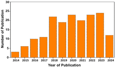 | ||
| Fig. 2 Statistical analysis of publications on fiber-based rechargeable batteries [source: Web of Science]. | ||
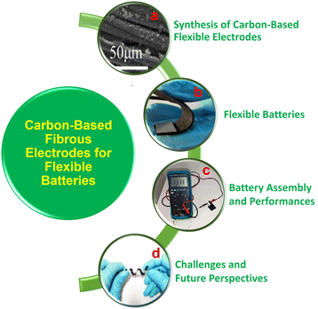 | ||
| Fig. 3 Contents of the present review. (a) Co3PO4 nanopetals grown over CF film and (b) ZAB fabricated with KOH/PVA polymer gel electrolyte shows high flexibility. Reproduced with permission from ref. 24. Copyright (2021), American Chemical Society. (c) Solid-state ZAB with CNT fiber treated as the air cathode. Reproduced with permission from ref. 25. Copyright (2018), American Chemical Society. (d) Digital image of a Zn–MnO2 cable battery, which twins around a roller pen, revealing the twisting. Reproduced with permission from ref. 26. Copyright (2018), American Chemical Society. | ||
2. Synthesis of carbon-based flexible fibrous electrodes for rechargeable batteries
The synthesis of CF with defined morphology and architecture has prominent interest in the fabrication of rechargeable batteries. A schematic representation of the synthesis methods used in CF-based flexible electrodes is shown in Fig. 4. This section illustrates the synthesis methods established for CF-based electrode materials.2.1 Synthesis of flexible electrodes by spray coating
One of the major limitations in the development of structural batteries is the requirement for positive electrode components. To develop batteries that are completely based on CF, it is imperative to demonstrate the cathode active material to these CFs. This necessitates the perfect coating of each of the individual fibers, which aims to optimize lightweight CF utilization and facilitate the transition from the micron to macroscopic scale application in a rechargeable battery. In accordance with this necessity, many studies have been established to design a prominent technique for the synthesis of CF. From this perspective, spray coating has been found to be an efficient route for the coating/synthesis of CF electrode materials for rechargeable battery applications. The spray coating process provides feasibility for depositing thick film to improve surface components taken from various classes of materials. The spray coating approach requires only a smaller amount of chemicals and has fewer steps for the procedure, thereby producing a reduced amount of waste during this synthesis. There is a report that establishes the spray coating technique of LiFePO4-coated CF for structural battery demonstration.27 A schematic representation of the spray coating apparatus is shown in Fig. 5. Here, 24k polyacrylonitrile (PAN)-derived CF type IMS65 was distributed manually and affixed in a 2 cm × 4 cm Kapton frame for easy handling. This frame was positioned over a hot plate and fixed at a temperature of 100 °C. Here, the spray gun of the apparatus was affixed in a holder positioned at a height of 8 cm above the CF samples, which ensured comprehensive coverage of the total fiber surface. This spraying procedure proceeded under ambient environment conditions. The gun is connected to a nitrogen inlet, which provides flow from the reservoir to the nozzle. The slurry for the electrode is loaded into the spray gun reservoir, and an equal quantity of slurry is applied to both sides of the CFs. A specific time interval is introduced during the spraying process to allow for the evaporation of the solvent, N-methylpyrrolidone and to settle solid particles on the CF surface. For a spray coating procedure, it is necessary to ensure the adhesion of sprayed particles on the CF surface properly. During continuous spraying, particles that are already deposited over CF may dislodge before giving them a chance to completely adhere. Hence, continuous spraying is found to be detrimental in controlling the homogeneity and thickness of the coating. Hence, the spraying process is performed in a batch-by-batch process, which allows the evaporation of the carrier solvent and the particles to settle over the CF substrate. Due to the higher boiling point of N-methylpyrrolidone and its reduced evaporation rate, there was ample time during the coating procedure for the sample to settle over CFs. The major disadvantage underlying the spray coating approach is the porosity of the coating because these spaces make liquid or air pass through them. In addition, there exists a limited control in its thickness, and it remains a hurdle to tune the CF structure.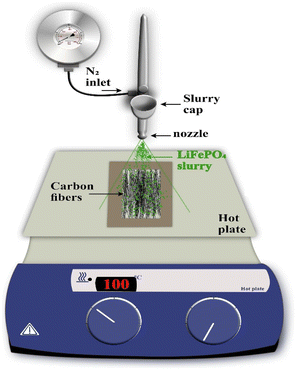 | ||
| Fig. 5 Spray-coating procedure set-up. Reproduced with permission from ref. 27. Copyright (2024) Elsevier Inc. | ||
2.2 Synthesis of flexible electrodes by electrochemical deposition
Electrochemical deposition involves coating a layer of material over a substrate by donating electrons to the ions in a solution. The electrochemical deposition procedure is a promising method for preparing coatings, and it is widely used in the case of pure forms of commercial Ti, Ti–6Al–4V and CF-reinforced carbon composites. The electrochemical deposition approach possesses properties such as a reduction in the quantity of waste material production, low cost and easy scalability of equipment used. In addition, through changes in optimization parameters, we can tailor crucial parameters in the coating process, such as morphology, roughness, and thickness.28 The implementation of this method for these materials is due to its moderate performance condition, easy way of operation, reduced instrumentation cost and control of process parameters. Control in thickness, structure of coating and chemical constitution results in excellent performance characteristics for the prepared fibers. There is a report based on the coating of nano-hydroxyapatite with favourable thickness and morphology on the surface of CF. Here, a mixed solution of hydrochloric acid, nitric acid, hydrogen peroxide and sulfuric acid was taken for preparation. The coating is fabricated through the combination of this mixed solution and electrochemical deposition. In the present study, CF was fabricated from the PAN precursor using a carbonization process. In the chemical treatment, CFs are initially cleaned through ultrasonication and sequentially with acetone, alcohol and distilled water at room temperature. After that, the cleaned CFs are divided into four groups of similar mass to determine the influence of various CF treatments on nano-hydroxyapatite deposition. Creating a higher quantity of functional groups over the CF surface is important for introducing nucleation and growth of CaP coating over fibers by interfacial chemical bonds. The higher the density value of the surface functional group, the higher the probability of a surface reaction, and it is efficient for the interfacial chemical bonding present between the coating and the fiber surface. From the field-emission scanning electron microscope (FESEM) imaging, the authors of the present work observed that the surface of the untreated CF was smooth without any apparent pitting. However, the surfaces of CF were rough and pitted after the treatment. In addition, the groves present over the surface of this treated CF were wider compared to the untreated one. The proposed results show that there exists an increase in the surface area value of this treated CF. This structure held by CF is highly related to their activity. Therefore, it is observed that electrochemical deposition is an efficient method for CF fibers to improve their activity in multifunctional applications.29 In addition to these advantages, the major demerit underlying the application of this route for CF fabrication is its expensive nature and dependency on environmental conditions. The utilization of toxic plating solutions also stands as a demerit in their widespread application.302.3 Synthesis of flexible electrodes by dip coating
Dip coating is an efficient route for preparing CF-based electrodes due to its facile nature and economic feasibility compared to other parallel routes. This is a widely used approach for preparing CF for many applications, especially in rechargeable batteries. Through the dip-coating process, it is possible to establish mass production of electrode materials in an easy, scalable and reproducible way. A simple formation mechanism for film through dip-coating facilitates tunability in morphology and thickness of prepared films without any hurdle experimental set-up.31 There is a report based on the fabrication of CF through the dip-coating process using the method of slurry immersion.32 For this proposed procedure of development, a batch of procedures is applied to continuously spooled fiber. Here, torsion spring pairs with about 130 mm (∼5 inches) were cut and bent at a right angle about the center. Aluminium cylinders with a diameter of 12.7 mm (∼0.5 inches) and length are prepared to have two radial holes drilled for each of them, which matches two radial holes drilled for each. These holes match the diameter of the torsion springs. Torsion springs are bonded to cylindrical ends with a small quantity of 3 M 2216 epoxy with completed tensioner matching (Fig. 6(a)). Each spring tensioner is perfectly cleaned prior to its initial use, and it is subsequently reused for removing adhered slurry material. In this study, a series of CF samples were prepared by cutting tows with a length of 280 mm, and it was clasped by 3 M 2216 epoxy for the creation of a circular loop, as depicted in Fig. 6(b). Here, the specimen's diameter is measured to be about a mean value of 65 mm in diameter after performing cutting. The CF cured specimen loops are placed onto a CF low-tension tool, which causes a torsion spring for compression to provide tension to the fiber specimen. It is most prior that there is a maintenance of tow width, and it is centered between torsion springs on either side of aluminium ends to avoid contact between torsion springs. The specimen must be placed in such a way that the epoxy clasp is not exposed to cathode slurry, which matches the position, as demonstrated in Fig. 6(c). The low-tension CF tool provides about 4–5 pounds of force to the fiber loop when it is compressed, which depends on deviation of the synthesized specimen diameter. Immediately before initiating the coating procedure, the cathode slurry is removed from the stirring plate and deposited into a machined aluminium trough, as illustrated in Fig. 6(d). This provides enough liquid for the completion of submerging the sample. Then, each of these CF specimens is submerged in cathodic slurry for 3 minutes (Fig. 6(e)), and it is removed and rested in an inverted position (Fig. 6(f)). Each of these specimens is kept for pre-dry at room temperature for a duration of 3 h, and it is transferred to a benchtop vacuum dry oven at a temperature of 50 °C for 12 h to dry. Specimens are supported in such a way that the CF becomes completely horizontal throughout the entire drying process. Beyond the advantageous hold of the dip-coating process for film preparation, it has a major drawback because light parts have floated off to the conveyor. Therefore, there is a variation in film thickness from the top to the bottom portion. Additionally, a fat edge is present at the bottom of the part when the excess amount of coating is lost, and solvent vapour reflux over the tank removes some of the coatings. Through the optimization of experimental conditions for dip-coating procedures, it is possible to prepare a uniform CF for practical applications in a more effective way.33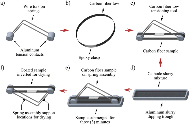 | ||
| Fig. 6 Illustration of various stages in the coating process of a CF cathode: (a) assembling of a fiber torsion tool with wire a torsion spring and aluminium tension contact, (b) fiber tow of the sample cut and clasped by epoxy, (c) fiber sample positioned over spring tensioner after curing the epoxy, (d) slurry mixture of the cathode mixed poured into aluminium through dipping, (e) sample of fiber tow submerged into cathode slurry and (f) spring tensioner fiber tow inverted to drying. Reproduced with permission from ref. 32. Copyright (2022), American Chemical Society. | ||
3. Electrochemical performance evaluation of carbon-based flexible fibrous electrodes for rechargeable batteries
Rechargeable batteries or secondary cells are electrochemical energy storage systems that can charge and discharge multiple times during their operation. They have attracted great attention in the recent past due to their salient features, such as mobility, light weight, low-cost, and high performance. Developments in the area of portable electronic devices and flexible derivable have introduced a higher demand for the evolution of rechargeable batteries, which possess higher energy and power density, flexibility and security. The given strategies cannot fully be achieved by LIB, and their energy density is restricted by Li capacity for longer applications. These batteries have a theoretical capacity of 120–320 mA h g−1. To modify the energy density of these devices, Yin et al.34 proposed that elements in group 16, such as sulfur (S), oxygen (O), selenium (Se) and tellurium (Te), can be used as a cathode for rechargeable batteries. They prepared Te nanorods by chemical vapour deposition (CVD) on CF film and assembled them directly into the solid-state Li–Te batteries containing solvent-free solid electrolytes of LiPF6 dissolved in a mixture of ethylene carbonate (EC) and dimethyl carbonate in a ratio of 1![[thin space (1/6-em)]](https://www.rsc.org/images/entities/char_2009.gif) :
:![[thin space (1/6-em)]](https://www.rsc.org/images/entities/char_2009.gif) 1. From the scanning electron microscope (SEM) images, the authors of this work found that Te is grown from CF, and the inner diameter and wall thickness of Te nanotubes are about 60 nm and 20 nm, respectively. The fabricated flexible Li–Te battery delivered a higher gravimetric capacity of 273 mA h g−1 and a volumetric capacity of 1707 mA h cm−3 after 500 cycles at a current density of 100 mA g−1. This battery delivered good flexibility, security and efficient electrochemical performance. The rapid diminishing of fossil fuels and environmental considerations introduced demonstrations in new generation energy storage and conversion technologies. In these technologies, rechargeable metal–air batteries have made significant progress due to their environmentally friendly features, reduced cost, large energy density and safer operation. However, the performance of these metal–air batteries is diminished by sluggish kinetics introduced by oxygen evolution reaction (OER) and oxygen reduction reaction (ORR). Among various materials, platinum (Pt)-based materials catalyses the ORR strongly, and ruthenium, iridium, etc. catalyses OER. However, catalysts have higher costs, reduced stability and lower earth abundance, limiting their application in metal–air batteries. Additionally, these catalysts have a single catalytic performance either as an ORR or OER. Numerous studies have been conducted to develop non-precious metal electrocatalysts, such as heteroatom-doped carbon catalysts and transition-metal-based catalysts. Transition-metal-based catalysts face problems such as reduced conductivity and degradation by the dissolution of metals.
1. From the scanning electron microscope (SEM) images, the authors of this work found that Te is grown from CF, and the inner diameter and wall thickness of Te nanotubes are about 60 nm and 20 nm, respectively. The fabricated flexible Li–Te battery delivered a higher gravimetric capacity of 273 mA h g−1 and a volumetric capacity of 1707 mA h cm−3 after 500 cycles at a current density of 100 mA g−1. This battery delivered good flexibility, security and efficient electrochemical performance. The rapid diminishing of fossil fuels and environmental considerations introduced demonstrations in new generation energy storage and conversion technologies. In these technologies, rechargeable metal–air batteries have made significant progress due to their environmentally friendly features, reduced cost, large energy density and safer operation. However, the performance of these metal–air batteries is diminished by sluggish kinetics introduced by oxygen evolution reaction (OER) and oxygen reduction reaction (ORR). Among various materials, platinum (Pt)-based materials catalyses the ORR strongly, and ruthenium, iridium, etc. catalyses OER. However, catalysts have higher costs, reduced stability and lower earth abundance, limiting their application in metal–air batteries. Additionally, these catalysts have a single catalytic performance either as an ORR or OER. Numerous studies have been conducted to develop non-precious metal electrocatalysts, such as heteroatom-doped carbon catalysts and transition-metal-based catalysts. Transition-metal-based catalysts face problems such as reduced conductivity and degradation by the dissolution of metals.
Currently, carbon-based electrocatalysts with heteroatom doped, which are free from metal, with lower cost and higher stability, have been widely discussed. From the experimental findings and theoretical calculation, it is found that the introduction of heteroatoms, such as B, F, P, S and N, into the carbon matrix can improve the ORR and OER activity by the polarization and alteration of the spin density of nearby carbon atoms. This introduces catalytically active sites that promote the adsorption/desorption of oxygen. Based on these facts, Wang et al.35 synthesized B, N and F-tri-doped lignin-based CFs (abbreviated as BNF-LCFs) through electrospinning, pre-oxidation and carbonization procedure. During the carbonization process, biomass lignin was used as a source of carbon precursor and polyvinylpyrrolidone as a spinning additive, zinc borate as a boron source, ammonium fluoride as a source of fluoride and as a partial nitrogen resource. The route is found to be simpler, more efficient and eco-friendly. The authors found that zinc borate and ammonium fluoride addition couldn't lead to the doping of B and F sources, but it helped in increasing the amount of N and the degree of defect in the carbon matrix. Here, zinc borate produces many pores and introduces a higher surface area, which holds large active sites. Their experimental studies reveal that the prepared BNF-LCFs possess fascinating ORR and OER catalytic activity and stability for electrochemical reactions. The as-assembled liquid ZAB consists of BNF-LCFs with a larger specific capacity of 791.5 mA h g−1 and good cyclic stability, which is higher than the value obtained for Pt/CF + RuO2. Due to the efficient flexibility of the BNF-LCFs, the fabricated ZAB exhibit good electrochemical performance and flexibility.
Fiber-shaped energy storage devices have received significant attention because of their reduced volume, good flexibility and ease of textile integration. However, its reduced energy density limits its practical application in daily life applications. Therefore, significant efforts have been devoted to increasing the energy density of these fiber-shaped energy devices. Rechargeable Ni/Fe aqueous batteries have been studied for the past few years, especially, owing to their safer operation due to the absence of organic electrolytes and large ionic conductivity with higher energy density at a reduced cost. However, its reduced power density and cyclic stability stand as demerits for its industrial application. Therefore, the selection of an efficient high-performing material is a suitable way to overcome this issue. Consequently, Liu et al.36 controlled the activity of α-Fe2O3 nanorod superstructure by their controlled synthesis over CFs by changing the growth time, which acted as a negative electrode without using a binder. Here, a positive electrode is prepared in a core–shell structure where cobalt–nickel oxide (CoNiO2) nanowires are used as the core and nickel hydroxide (Ni(OH)2) nanosheets act as the shell. This flexible fiber-shaped energy storage device is assembled using a potassium hydroxide (KOH)-polyvinyl alcohol (PVA) gel electrolyte with a working voltage of 1.6 V. The device delivered a specific capacity of 0.62 A h cm−3 and a volumetric energy density of 15.47 mW h cm−3 with 228.2 mW h cm−3 at a current density of 1 A cm−3. The fabricated device has a cyclic stability of 90.1% after 2500 cycles at a bending angle of 180°. This work reveals the significance of the fabrication of flexible devices using CF.
3.1 Metal-ion battery
Reduced Li resources, flammability induced by organic electrolytes and reduction in electrochemical performance produced by LIBs introduced the necessity for researchers to focus their views on other battery devices. From these perspectives, metal-ion batteries, specifically zinc-ion batteries (ZIBs), have recently received great attention. However, it is found that ZIBs have a reduction in their electrochemical performance due to dendrite formation. Therefore, significant efforts have been devoted to modify its performance. To deal with this issue, the introduction of some substrates, such as Ni and Cu, and some additives, modifies the performance. Inspired by this, Qian et al.37 used a simple and facile method in which they electrochemically coated a zinc-philic Cu nanosheet layer on an activated carbon cloth (CC) as a flexible 3D current collector. The small size metallic Cu particles did not make a complete wrap over CF for a deposition of 300 s. With respect to an increase in the deposition time, CF makes a complete covering by Cu, which forms a uniform copper layer. The authors of this work found that the as-prepared Zn with modified surfaces consists of a higher amount of large-sized nanosheets, but in the case of Zn with Cu on a CC surface, it consists of Zn particles of a small size. Their experimental analysis shows that the Cu nanosheet reduces the nucleation of Zn, increasing the surface area and electronic conductivity, and it leads to the deposition of Zn on a current collector in a uniform way during the charge/discharge process. Here, MnO2 with activated-CC was used as the cathode. The assembled flexible device has a higher capacitive retention of about 94.8% and a coulombic efficiency of 97.9% after 100 cycles at a current density of 1 A g−1. This higher performance is achieved through the higher affinity of Cu to Zn, the presence of abundant active sites, and the uniform distribution of the Cu nanosheet layer over activated-CC, acting as Zn deposition seeds. Prominently, the Cu nanosheet coating layer over activated-CC acts as a current collector, increases the specific surface and reduces the nucleation hindrance of Zn. During the plating/striping procedure of Zn, the Zn2+ was initially nucleated and deposited over Cu seeds, and further, it grew to Zn spherical metal particles. In the final stage, the separated Zn spheres are connected together, and they are developed into a dense layer that covers the entire anode surface. In comparison to homogeneous deposition by Zn over Cu nanosheets with activated-CC, the procedure for Zn deposition during cycles is entirely different. In accordance with the reduced specific surface area and a small number of deposition sites of activated-CC, the deposition of Zn tends to proceed at deposition sites, which leads to uneven growth during cycles and ultimately leads to the formation of dendrites.3.2 Metal–air battery
Rechargeable metal–air batteries are considered a future battery resource for multifunctional applications. Ji et al.38 introduced a facile free-spinning strategy followed by a carbonization technique to mass synthesize nonprecious transition metal incorporated carbon nanotube (CNT) on carbon-nanofiber films (CNFFs) (abbreviated as MNO-CNT-CNFFs, where, M = Fe, Co, Ni). The fabrication process is presented in Fig. 7(a). Initially, the solution consists of PAN, cellulose acetate and iron(III) acetylacetonate dissolved into N,N-dimethylformamide, and it acts as a spinning precursor for the mass synthesis of the metal-rich nanofiber film (M-NFF), as shown in Fig. 7(b). The as-prepared M-NFF is then stabilized at a temperature of 280 °C, as depicted in Fig. 7(c), after applying a carbonization treatment at a temperature of 800 °C to pyrolyze this stabilized M-NFF in the presence of melamine. In this process of carbonization, melamine undergoes pyrolysis to produce graphitic carbon nitride deposited on the M-NFF. During this procedure, cellulose acetate decomposes by the release of oxygen-containing gas, leaving the channels in the carbonized PAN fibers. The introduction of these channels produces benefits for exposing transition metals that act as catalysts for CNT growth and the creation of an MNO-CNT active material. MNO-CNT-CNFFs in a uniform and free-standing structure (Fig. 7(d)) is generated after cooling the carbonized product to room temperature.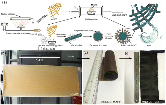 | ||
| Fig. 7 (a) Pictorial representation of the fabrication process of MNO-CNT-CNFFs; (b) mass production step for Fe–NFF using free-surface electrospinning technique in 15 min, and size of the prepared film is 180 × 80 cm2; (c) MNFFs stabilized; and (d) prepared MNO-CNT-CNFFs obtained after carbonization with melamine. Reproduced with permission from ref. 38. Copyright (2017), American Chemical Society. | ||
Fig. 8 illustrates an idea of the morphology of as-synthesized MNO-CNT-CNFFs. The SEM images clearly represent the growth of Fe, Ni and Co catalysed CNTs. Fig. 8(a–c) shows that the CFs prepared by applying the electrospun technique have a diameter of 600 nm, and they have homogenous coverage by the peapod-like structured Fe-based CNTs, which are in situ grown. These peapods have a diameter of 10–30 nm with a length range of several hundred nanometers. Well-crystallized peapods have a diameter of 5–20 nm with a lattice distance of ∼0.21 nm (Fig. 8(e)). X-ray diffraction (XRD) pattern shown in Fig. 8(f) confirm the crystalline nature of Fe3C and cubic Fe. The transmission electron microscope (TEM) image depicted in Fig. 8(d) has an empty and hollow peapod-like structure, which tends to increase the surface area to increase its catalytic activity. The TEM image of CNT depicted in Fig. 8(d) and (e) shows that lattice fringes have an interplanar distance of ∼0.34 nm, which corresponds to the C (002) plane, and it has a higher amount of exposed edge sites, which improves the catalytic activity. The elemental mapping images in Fig. 8(g–k) illustrate that there exists a uniform distribution of C, O, N and Fe in the sample.
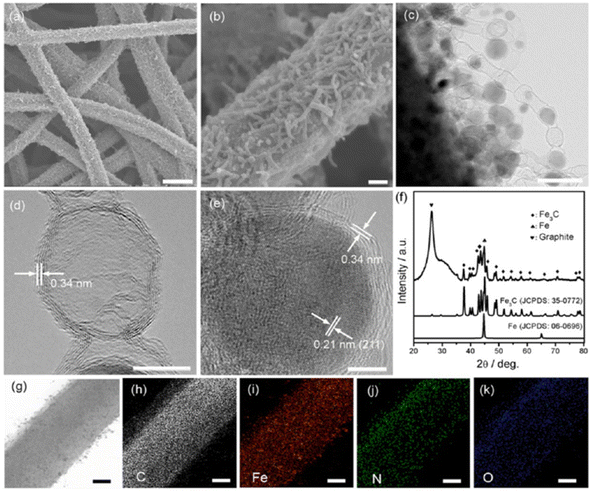 | ||
| Fig. 8 (a and b) SEM image of FeNO-CNT-CNFF, (c–e) TEM image, (f) XRD pattern of FeNO-CNT-CNFF, and (g–k) elemental mapping images of C, O, Fe and N. Reproduced with permission from ref. 38. Copyright (2017), American Chemical Society. | ||
Due to efficient bifunctional electrocatalytic features and novel physical characteristics, FeNO-CNT-CNFF melamine treated at 800 °C is further used as an air electrode to fabricate rechargeable hybrid Li–air battery (LAB). The pictorial representation of a rechargeable LAB consisting of an Li metal anode and NASICON-type Li1.5Al0.5Ge1.5(PO4)3 as an anode protecting membrane is shown in Fig. 9(a). The constructed anode chamber consisting of 1 M LiPF6 in EC-dimethyl carbonate to reduce the interfacial resistance. Additionally, 1 M LiOH aqueous solution is applied as a catholyte solution. This hybrid LAB achieves a higher voltage of ∼3.4 V and is used to lighten the LED to reveal its commercial application (Fig. 9(b)). A comparison of the charge/discharge curve of hybrid cells using various cathodes is depicted in Fig. 9(c). The fabricated battery material exhibits effective operation with a voltage window of 0.15 V in a current density of 0.03 mA cm−2, and this value is smaller than the Pt/C + Ir/C air electrode. Fig. 9(d) shows that the hybrid LAB performs a stable reduction of 4e− performance in different current densities. Fig. 9(e) and (f) illustrate stability after 20 cycles while exhibiting a specific capacity of 30 mA h g−1.
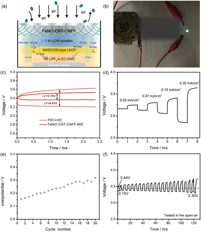 | ||
| Fig. 9 (a) Pictorial representation of a rechargeable LAB, (b) digital photograph of FeNO-CNT-CNFF-based hybrid LAB lighting the LED, (c) voltage gap comparison of charge/discharge voltage plateau with different catalysts for the LAB, (d) charge/discharge curve of the as-prepared LAB with various current densities, (e) change in overpotential of the LAB with change in the cycle number, and (f) cycling performance analysis of the LAB under an open-air condition. Reproduced with permission from ref. 38. Copyright (2017), American Chemical Society. | ||
3.3 Zin–air battery
The zinc–air battery (ZAB) is a relatively new concept in the field of rechargeable batteries. Hou et al.24 fabricated a hybrid energy device composed of rechargeable ZAB with an asymmetric supercapacitor constructed on a CC film. Here, the nanostructured cobalt(II) phosphate (Co3PO4) is grown on CC by electrochemical deposition using a constant voltage method. Here, the electrochemical deposition approach is utilized because this procedure establishes a uniform distribution of Co3PO4 nanostructures over the CC. An overall arrangement of both devices in a sandwich-like structure is illustrated in Fig. 10(a). In this arrangement, the Co3PO4/CC acts as the positive electrode, KOH/PVA as the gel electrolyte, and an activated carbon (AC)/CC composite is used to fabricate the asymmetric supercapacitor portion and Co3PO4/CC nanocomposite as the air electrode; KOH/PVA gel electrolyte and Zn foil as the negative electrode construct the ZAB portion. With the microscopic view of the constructed system (Fig. 10(b)), it is clear that a distinct boundary line exists over CC with a highly dense black colour representing the higher amount of load of Co3PO4 and light colour shows the low load percentage of Co3PO4. From the SEM images, it was observed that a higher percentage of Co3PO4 loading introduced the generation of vertically sprouting nanopetals and clusters, making a uniform distribution over the CF surface (Fig. 10(c)), and the lower quantity of Co3PO4 loading produces ultrathin nanocoating that wraps uniformly over the surface of CFs (Fig. 10(d)). Fig. 10(e) depicts the introduction of a solid-state gel, and Fig. 10(f) shows the flexibility of these films. As prepared, the gel electrolyte bonds with both the positive and negative electrodes as a solid-state integrated system (Fig. 10(g)). Due to the presence of this gel electrode, the assembled hybrid system also shows efficient flexibility (Fig. 10(h)).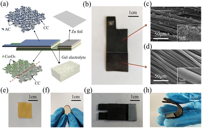 | ||
| Fig. 10 (a) Pictorial representation of a solid-state integrated hybrid energy system and (b) digital picture of a Co3PO4/CC nanocomposite. SEM image representing (c) the higher loading amount of Co3PO4 nanopetals over CF film (inset shows higher magnification image) and (d) lower loading of Co3PO4 nano-coatings over CF for the ZAB part (inset shows higher magnification image) . Digital images showing the (e) KOH/PVA gel electrolyte film retaining water, (f) its flexible state, (g) top view of the integrated device, and (h) state of its flexibility. Reproduced with permission from ref. 24. Copyright (2021), American Chemical Society. | ||
The authors of this work have analysed the performance of the hybrid energy storage system. Fig. 11(a) describes the equivalent circuit diagram, which provides an idea of the mode of operation of the hybrid energy storage system. Here, the single-pole double throw switch was utilized to achieve the instant switch of performance by the in situ charging from the asymmetric supercapacitor to its external power source. In the asymmetric supercapacitor part, the voltage initially increases up to 1.0 V in few seconds; then, it approaches a value of 1.15 V after 200 s of charging. During the in situ charging process, the chemical energy, which originated from the ZAB, is converted to electrical energy, and it is stored in an asymmetric supercapacitor portion in a slow step process. Accordingly, the voltage of the asymmetric supercapacitor decreases to 0 V, as shown in the red curve in Fig. 11(b). The external performance of the pulse formed was obtained at a peak discharge current of 55 mA for 5 s (Fig. 11(c)). The device has a higher power density of 7.91 mW cm−2 at an output voltage of 1.15 V and a peak current of 0.055 A with an area of 8 cm−2. A comparison of the change in voltage of asymmetric supercapacitor and ZAB in 1, 25 and 50 cycles is given. The output working voltage in ZAB is found to be stable at 1.17 V in the first cycle, then it decreases to 1.13 V in the 25th cycle, and it reaches 1.0 V in the 50th cycle (Fig. 11(d)). A comparison of the maximum voltage achieved by the asymmetric supercapacitor is presented in Fig. 11(e), which is produced by the in situ charging process carried out in 200 s during the first and second inner cycles. The selection of proper electrocatalysts, which can catalyse ORR and OER, is given prior importance for the fabrication of metal–air batteries.
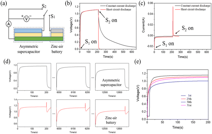 | ||
| Fig. 11 (a) Equivalent circuit of a hybrid energy system, change in voltage (b) and current (c) of an asymmetric supercapacitor at constant current discharge and short circuit discharge, (d) change in the voltage of the asymmetric supercapacitor and ZAB in their 1st, 25th and 50th cycle. (e) Comparison on the charge voltage curve of asymmetric supercapacitor for its 1st, 25th, 50th and 51st cycle. Reproduced with permission from ref. 24. Copyright (2021), American Chemical Society. | ||
3.4 Flexible CF battery
By considering the demand for the fabrication of flexible battery systems, Pendashteh et al.25 fabricated a self-standing air-cathode based on CNT fibers (CNTfs) prepared by CVD, followed by a hydrothermal method. The electrocatalytic activity of the prepared fibers is optimized by tuning N-doping and defect density, which can be adjusted with the hydrothermal temperature. The TEM image demonstrated in Fig. 12(a) shows that fibers consist of interconnected CNTs, which possess a crystalline multiwalled structure with 3–5 layers with a diameter <10 nm, as depicted in the inset image. The X-ray photoelectron spectroscopy (XPS) survey spectra depicted in Fig. 12(b) clearly show the introduction of the N 1s peak and the increase in the intensity of the O 1s peak after the treatment. From the inset C 1s data fitting, there exists a continuous increase in the sp3/sp2 ratio after the N-doping and an increase in the O/C ratio and a further reduction, particularly for the N-CNTf-190 sample, as depicted in the inset graph of Fig. 12(b). An increase in the maximum O content in the sample synthesized at a temperature of 170 °C was introduced by the functional groups adsorbed, producing a redistribution of charges in the adjacent carbons. This redistribution of charges produces an increase in intermediate species adsorption for ORR and OER, which improves the catalytic properties of CNTfs. There exists a shifting of the C 1 s line towards higher values of binding energy, which agrees with the results obtained for N-doped CNTfs (Fig. 12(c)). The variation in the full width at half maximum of the N-doped CNTf samples with respect to the pristine CNTf is depicted as an inset plot of Fig. 12(c). From the peak analysis diagram shown in Fig. 12(d), it is clear that N-doped CNTfs synthesized at 170 °C hold a higher amount of pyridinic-N atoms. It produces the adsorption of oxygen atoms and the decomposition of hydroperoxide. Here, a ZAB is assembled using CNTf as an air cathode for liquid-based ZAB using an alkaline PVA-based polymer gel electrolyte. This assembled battery shows an open circuit voltage of 1.31 V (Fig. 13), and there is at least 50 mV in ZAB. A schematic representation of the battery and reaction mechanism during the discharge is also depicted in Fig. 13, where CNT-170 catalyses the ORR by the 4e− pathway, but Zn is oxidized and zincate species are formed. Fig. 13 also showed the charge/discharge profile of ZAB, which exhibit flat voltage plateaus observed at 1.97 and 0.87 V in charging and discharging, respectively. It is also clear that the profile did not cause any alteration during bending of the ZAB.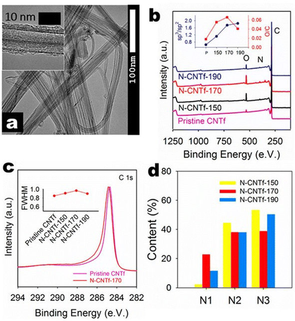 | ||
| Fig. 12 (a) TEM image of fiber treated at 170 °C (inset shows the TEM image of single fiber). (b) XPS survey spectra of various CNTf samples (inset plot represents the sp3 to sp2 ratio and O to C ratio for various CNTf samples. (c) XPS C 1s spectra in high-resolution for the pristine CNTf sample and CNTf treated at 170 °C (inset plot shows the full width at half maximum of various CNTf samples), and (d) XPS core level N 1s spectra for the N-doped CNTf samples. Reproduced with permission from ref. 25. Copyright (2018), American Chemical Society. | ||
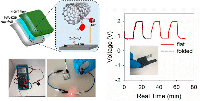 | ||
| Fig. 13 Pictorial representation of prepared rechargeable solid-state ZAB with CNT fiber treated as the air cathode and PVA-KOH as gel electrolyte (left panel). The right panel represents the GCD profile of the solid-state ZAB in the flat and bend states. Reproduced with permission from ref. 25 Copyright (2018), American Chemical Society. | ||
Due to the excellent bifunctional catalytic activity of the sample at 170 °C as an air cathode for liquid-based ZAB with alkaline poly(vinyl alcohol) as a gel electrolyte constructed. The fabricated device shows a higher open circuit voltage of 1.31 V, which is about 50 mV lower than the liquid-base battery. Here, the prepared electrode material catalyses the ORR via the 4e route. The anode Zn oxidizes, and zincate species such as Zn(OH)42− is produced. In the charging process, there occurs a reverse reaction and an evolution of oxygen in the CNT fibers. From the charge/discharge diagram, we can observe that there exists a flat voltage plateau in the regions of 1.97 and 0.87 V in the charging and discharging processes, respectively. It is also observed that there is no bending of the cell. Additionally, there exists a red LED that is lightened by the two batteries, which are connected in a series connection. This confirms the efficient performance of the prepared electrode material for the fabrication of a solid device, which was formed by the defects and doping introduced into the CNT fibers. Their experimental analysis shows that the treated CNT fibers act as an efficient tool for the fabrication of flexible and lightweight ZABs.
Du et al.39 fabricated a flexible electrode material comprising of tin sulfide (SnS)@CFs by an electrospinning approach. There is an introduction of a chelate complex with L-cysteine and metal cations. By considering SnS as a representative material, a fiber electrode with flexibility is developed by interweaving this material into CF in a continuous manner. In the half cell fabricated, Li (for SIBs, Na) acted as counter and reference electrodes. Here, 1 M LiPF6 is used as the electrolyte consisting of the solvent ethylene carbonate (EC) and diethyl carbonate (DEC) in a ratio of 1![[thin space (1/6-em)]](https://www.rsc.org/images/entities/char_2009.gif) :
:![[thin space (1/6-em)]](https://www.rsc.org/images/entities/char_2009.gif) 1. In the case of SIB, 1 M NaClO4 acts as the electrolyte that consists of solvents, such as EC, DEC and propylene carbonate, in a ratio of 4
1. In the case of SIB, 1 M NaClO4 acts as the electrolyte that consists of solvents, such as EC, DEC and propylene carbonate, in a ratio of 4![[thin space (1/6-em)]](https://www.rsc.org/images/entities/char_2009.gif) :
:![[thin space (1/6-em)]](https://www.rsc.org/images/entities/char_2009.gif) 2
2![[thin space (1/6-em)]](https://www.rsc.org/images/entities/char_2009.gif) :
:![[thin space (1/6-em)]](https://www.rsc.org/images/entities/char_2009.gif) 2. Additionally, both of them contain 5% fluoroethylene carbonate. The synthesis procedure of the electrode material is illustrated in Fig. 14(a). In this study, the authors choose polyvinylpyrrolidone/metal salt/L-cysteine and PAN as the precursors for the core and shell layers, respectively. L-Cysteine has three ligands (thiol group (R–SH), carboxyl group (R–COOH), and amino group (R–NH2)), which produce a bond with the metal-ion to create a chelate complex (Fig. 14(b)). Fourier-transform infrared (FTIR) spectroscopy was used to analyze the bonding between SnCl2 and L-cysteine. The absorption peak present at 2552 and 942 cm−1 represents the characteristic peak of R–SH in L-cysteine, and it is found to disappear in the SnCl2 and L-cysteine mixed solution. Moreover, in the chelate complex, peaks positioned at 2082 and 1532 cm−1 corresponding to the R–NH2 group are absent, which indicates that coordination is introduced between Sn2+ and a nitrogen atom. Based on the results obtained from FTIR, the molecular structure held by the chelate complex is shown in Fig. 14(c).
2. Additionally, both of them contain 5% fluoroethylene carbonate. The synthesis procedure of the electrode material is illustrated in Fig. 14(a). In this study, the authors choose polyvinylpyrrolidone/metal salt/L-cysteine and PAN as the precursors for the core and shell layers, respectively. L-Cysteine has three ligands (thiol group (R–SH), carboxyl group (R–COOH), and amino group (R–NH2)), which produce a bond with the metal-ion to create a chelate complex (Fig. 14(b)). Fourier-transform infrared (FTIR) spectroscopy was used to analyze the bonding between SnCl2 and L-cysteine. The absorption peak present at 2552 and 942 cm−1 represents the characteristic peak of R–SH in L-cysteine, and it is found to disappear in the SnCl2 and L-cysteine mixed solution. Moreover, in the chelate complex, peaks positioned at 2082 and 1532 cm−1 corresponding to the R–NH2 group are absent, which indicates that coordination is introduced between Sn2+ and a nitrogen atom. Based on the results obtained from FTIR, the molecular structure held by the chelate complex is shown in Fig. 14(c).
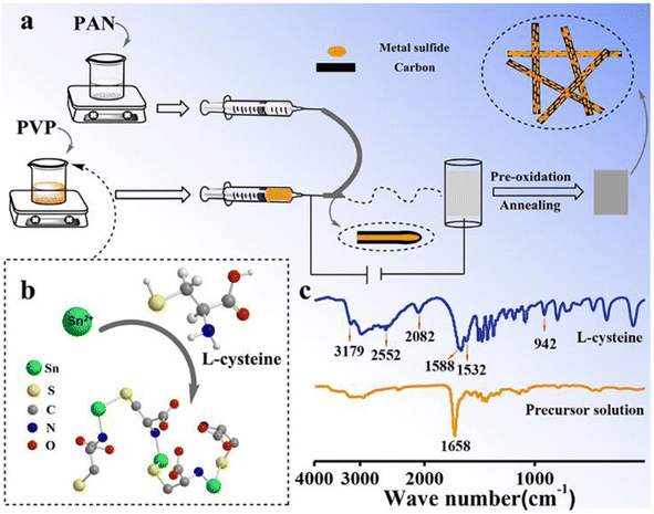 | ||
| Fig. 14 (a) Pictorial representation of synthesis procedure of SnS@CF via electrospinning, (b) structure of the chelate complex formed by L-cysteine and metal cation, and (c) FTIR spectra of L-cysteine and mixed solution of SnCl2 and L-cysteine. Reproduced with permission from ref. 39. Copyright (2019), American Chemical Society. | ||
The XRD spectrum of Uni-SnS/C prepared by the single axial electrospinning of a similar solution of core-layer Coa-SnS/C is shown in Fig. 15(a). The SEM images of Uni-SnS/C and Coa-SnS/C fibers are depicted in Fig. 15(b) and (c), respectively and the inset graphs represent the percentage of fibers that lie within a particular diameter range. Other than a rough morphology, the fibers exhibit a smooth surface. Coa-SnS/C electrode at its flat position is depicted in Fig. 15(d) and exhibit good flexibility at severe bending and twisting, as depicted in the inset image of Fig. 15(d). From the TEM and high-resolution TEM (HRTEM) images shown in Fig. 15(e) and (f), respectively, it is clear that the SnS is well assembled into the carbon matrix introduced by the confinement produced by the outer layer, producing the fast transfer of electrons and efficient buffering through charge/discharge process. A HRTEM image lattice fringe pattern of the Coa-SnS/C is given as an inset image of Fig. 15(f). The results obtained from XRD and TEM analyses show that the Coa-SnS/C exhibit an amorphous structure and can be prepared as an electrode material suitable for SIBs and LIBs.
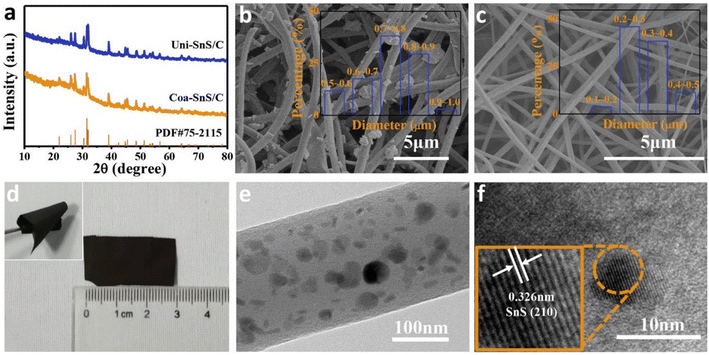 | ||
| Fig. 15 (a) XRD spectra of Uni-SnS/C and Coa-SnS/C. SEM image of (b) Uni-SnS/C (inset image shows the percentage of fibers having diameter fall within a particular range), (c) Coa-SnS/C electrode (inset image shows the percentage of fibers having diameter fall within a particular range), (d) photograph of Coa-SnS/C electrode in its flat position (inset image shows the electrode twisted multiple times), (e) TEM image of Coa-SnS/C, and (f) HRTEM image of single Coa-SnS/C (inset shows the HRTEM image lattice fringe pattern). Reproduced with permission from ref. 39. Copyright (2019), American Chemical Society. | ||
Li/Na storage capability of the fabricated Coa-SnS/C electrode is analysed using electrochemical studies. Fig. 16(b) and (e) depict the cyclic voltammetry (CV) curves for the Li and Na storage, respectively. The CV study was performed for the first three cycles with a scan rate of 0.1 mV s−1 within a voltage window of 0.01–2.5 V. During the Li storage process, in the initial cathodic scan, the reduction peak originating at 1.34 V represents the process of converting SnS to Sn and Li2S. The peak at 1.34 V is the alloying reaction between Sn and Li. In the initial anodic scan, peaks at 0.50, 0.62, 0.80, and 1.18 V correspond to the multiple step Li–Sn dealloying procedure, and a wide peak at 2.0 V is the reversible conversion of Sn and Li2S to SnS phase. Similar to Li storage, the CV curves obtained for Na storage consisted of a reduction peak corresponding to the conversion and alloying reaction (Fig. 16(d) and (f)). The charge/discharge curves of Coa-SnS/C with respect to Li and Na storage are illustrated in Fig. 16(a) and (d), respectively, which are obtained at a constant current density of 50 mA g−1 within a voltage window of 0.0–2.5 V. First, the discharge/charge capacity attains a value of 1155.3/812.7 mA h g−1 for the storage of Li and 500.8/327 mA h g−1 for the Na storage with coulombic efficiency of 70.3% and 65.3%, respectively. A reduced capacity for SIB is connected with the broader and weaker CV peak for the storage of Na-ions introduced by the sluggish kinetic insertion and extraction of Na-ions. The rate performance of Coa-SnS/C anode for LIB is depicted in Fig. 16(c). The anode achieves reversible capacities of 752.1, 633.4, 556.7, 484, 389.7, and 317.9 mA h g−1 at different current densities of 50, 200, 500, 1000, 2000, and 5000 mA g−1, respectively. It exhibited an efficient cyclic stability where the specific capacity is about 403.9 mA h g−1 after 400 cycles at a current density of 1 A g−1 and achieved a coulombic efficiency of 99.8% at 1 and 2 A g−1 during cycling (Fig. 16(g) and (h)).
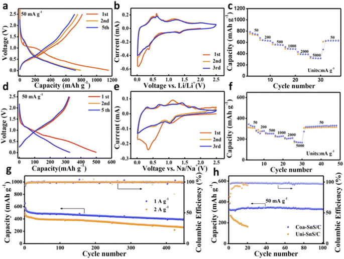 | ||
| Fig. 16 Electrochemical analysis of (a–c and g) for Li and (d–f and h) for Na (a and c) GCD profile of Coa-SnS/C at 50 mA g−1, (b and e) CV curve of Coa-SnS/C at 0.1 mV s−1 for first three cycles, (c and f) rate capability of Coa-SnS/C, (g) cycling stability evaluation of Coa-SnS/C for the storage of Li ions at 1 A g−1 and 2 A g−1, and (h) cycling stability analysis of Uni-SnS/C and Coa-SnS/C at 50 mA g−1. Reproduced with permission from ref. 39. Copyright (2019), American Chemical Society. | ||
In the textile industry, the fabrication of printable and flexible energy devices is one of the necessary things. Consequently, De et al.21 fabricated a copper-coated CF (Cu-CF) by electroless deposition route without applying any external power source for a solid state flexible battery device. This Cu-CF employed to prepare a poly(ethylene oxide) (PEO)-based polymer nanocomposite is used as a flexible and conductive current collector layer. The synthesis of materials for the design of a solid-state battery and its fabrication procedure is shown in Fig. 17(a–i). Cu2+ salt is reduced by formaldehyde (HCHO) in the presence of NaOH and is deposited on CFs, where the redox potential of copper is found to be more electropositive than carbon. Then, the cathodic reaction continues until the CFs are covered by Cu. To make a compromise to the reduction of adhesion introduced during the coating of CFs, a small amount of benzonitrozole is added. Through copper deposition, the potential involved in the potential is lower than +0.337 V, where copper ions are found to be thermodynamically stable when the potential is above this value in an acidic medium. The electrochemical performance of the battery is analysed using open circuit voltage (OCV) with and without current collector are illustrated in Fig. 18(a). Before starting the OCV analysis, the batteries are fully charged at a current of 0.04 mA. OCV measurements are performed for up to 100 min with Al foil as an electron collector on the anode, and the value reaches 2.67 V whereas it was only 0.67 V in the absence of an electron collector atthe anode side. The charge/discharge curves of the battery in repeated bending (where folding and unfolding are performed) at different bending angles of 30–180° is performed to examine its flexibility, as shown in Fig. 18(b). The digital images of bending the battery at different bending angles is given in the inset of Fig. 18(b). The charging cycles at a constant current of 0.01, 0.02, 0.03, and 0.04 mA for 1000 s, where the charging is initiated in the range of ∼1.6–2 V (Fig. 18(c)). The charge curve with a current of 0.01 mA reached a maximum voltage of 2.62 V. By reducing the charge current applied, the voltage is reduced in a fixed charge time. The highest voltage obtained for 0.04 mA is 2.66 V, which is also found in the discharge cycle shown in Fig. 18(d).
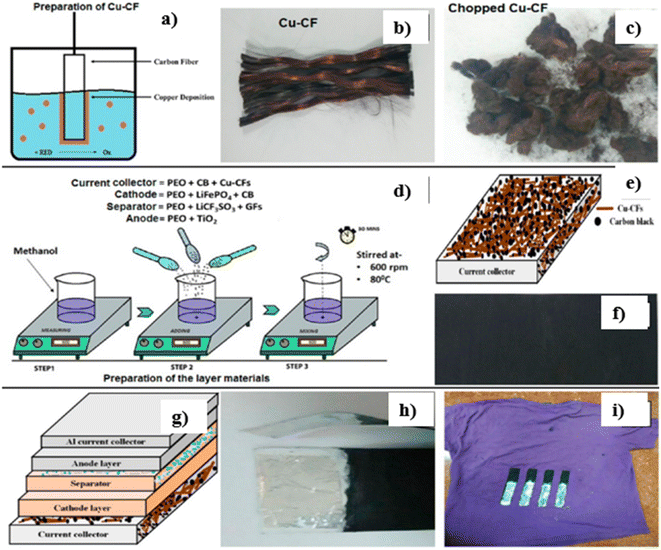 | ||
| Fig. 17 (a) Procedure for the electroless deposition of Cu-CFs. Digital image of (b) Cu-CFs and (c) chopped Cu-CFs. (d) Diagrammatic representation of fabrication of the electrode, electrolyte and current collector layer. (e) Pictorial representation of the current collector layer. (f) Digital image of the current collector layer. (g) Diagrammatic representation of a flexible fabric battery consisting of the component layers. Digital images of (h) an individual battery and (i) battery-coated over a fabric. Reproduced with permission from ref. 21. Copyright (2017), American Chemical Society. | ||
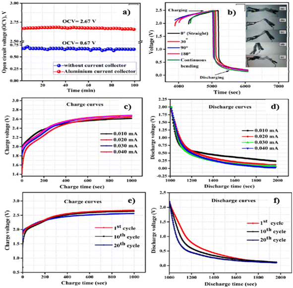 | ||
| Fig. 18 (a) Analysis of the OCV of the battery and (b) charge/discharge curves of the battery at different bending angles (inset images depict the digital images of the battery bent at different bending angles). (c) Charging curves and (d) discharging curves of the battery at fixed currents of 0.01, 0.02, 0.03, and 0.04 mA. (e) Charging curves and (f) discharging curves of the battery obtained at 1st, 10th and 20th cycles. Reproduced with permission from ref. 21. Copyright (2017), American Chemical Society. | ||
The charging curves and discharging curves obtained for the battery at its various cycle numbers is depicted in Fig. 18(e) and (f), respectively. Fig. 18(e) shows that the voltage decrease obtained between the 1st and 10th cycles is about 0.02 V, and it increases to 0.08 V after the 10th and 20th cycles. Fig. 18(f) shows the discharge curve of the 1st, 10th and 20th cycles, exhibiting similar discharge times. This is due to the efficient retention of integrity in the structure of the battery for electrochemical operation.
Wang et al.26 fabricated a linear-shaped battery in a one-dimensional structure with omni-directional flexibility. They fabricated a flexible cable-type solid-state rechargeable metal micro-battery of Zn–MnO2 on MnO2@CNT fiber composite electrode. CNT fiber with a diameter in the range of 80–100 μm is synthesized by direct dry spinning from CNT arrays assembled in a floating catalytic CVD reactor. MnO2@CNT fiber is fabricated by facile electrochemical deposition within aqueous Mn(NO3)2 solution. This cable type battery is assembled by binder-free MnO2@CNT fiber as cathode and Zn wire as anode, as shown in Fig. 19(a). From the XRD spectra illustrated in Fig. 19(b), it is clear that CNT fiber possesses a graphite-like structure with higher crystallinity. The XRD pattern of MnO2@CNT fiber shows that MnO2 grown over the CNT surface is an Arkhtenskite having a hexagonal structure with a P63/mmc space group. The Raman spectra depicted in Fig. 19(c) form a clear difference in the D-band, G-band and 2D-band. For the XPS spectra (Fig. 19(d)), the peaks located at a binding energy of 642 eV are assigned to Mn 2p3/2, confirming that manganese is in chemical state Mn4+, as shown in Fig. 19(e). The CNT fiber in a continuous pattern was synthesized during the direct dry-spinning of CNT formation in the CVD reaction zone, and it tended to be wound and collected in a mandrel (Fig. 20(a)). CNT fiber has a diameter in the range of 80–100 μm (Fig. 20(b)). Additionally, CNT fiber contains CNT bundles with a diameter of 10 nm (Fig. 20(c)). After depositing MnO2 for 30 min, CNT fiber holds a diameter of 100–120 μm (Fig. 20(d)). From the high-resolution SEM image (Fig. 20(e) and (f)), it is found that MnO2 nanosheets tend to be intertwined, and they are distributed vertically over the surface of CNT fibers and forms MnO2@CNT composite fiber. The energy-dispersive X-ray spectra mapping analysis showed that Mn and O are distributed uniformly over the surface of the CNT fiber, confirming the deposition of MnO2 on the CNT surface, as shown in Fig. 20(g–i).
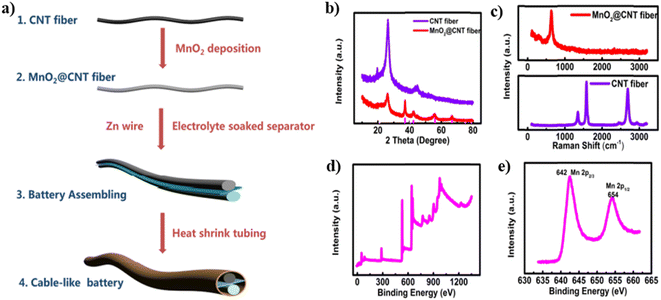 | ||
| Fig. 19 (a) Diagrammatic representation of the fabrication procedure of Zn–MnO2 cable battery with MnO2@CNT fibers as the cathode and Zn wire as anode, (b) XRD and (c) Raman spectra of MnO2@CNT fiber and CNT fiber, (d) XPS spectra of MnO2@CNT fibers and (e) Mn 2p spectrum of MnO2@CNT composite fibers. Reproduced with permission from ref. 26. Copyright (2018). American Chemical Society. | ||
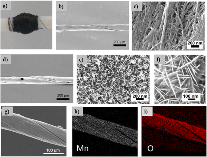 | ||
| Fig. 20 (a) Image of CNT fiber twined to a mandrel, (b and c) SEM image of CNT fibers at low and higher magnifications, (d–f) SEM image of MnO2@CNT fibers in various magnifications and (g–i) energy-dispersive X-ray spectra mapping images of MnO2@CNT fibers distributed for Mn and O. Reproduced with permission from ref. 26. Copyright (2018), American Chemical Society. | ||
Fabricated Zn–MnO2 batteries have prominent flexibility, and they can bend in any direction without introducing a reduction in their performance. Fig. 21(a) shows that Zn–MnO2 is wrapped around a pen, revealing its efficient bendability. To show the efficiency of the battery for real-time applications, an LED is connected to two Zn–MnO2 cable batteries, which could light-up the LED as shown in Fig. 21(b). To evaluate its electrochemical capability in different bending states, the cable battery tends to bend from its normal flat position (termed as State 1) to its bending state (termed as State 2), as depicted in Fig. 21(c) and (d), respectively. There is no reduction in the electrochemical performance to the Zn–MnO2 battery is observed during the change of states, which is evident from the charge/discharge curves depicted in Fig. 21(e). After completing 100 cycles of consecutive bending of the battery, there was no significant change in the charge/discharge performance, as illustrated in Fig. 21(f).
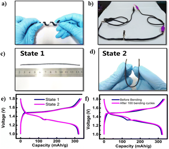 | ||
| Fig. 21 (a) Digital image of a Zn–MnO2 cable battery, which twins around a roller pen, revealing the twisting. (b) Two cable batteries that lighted-up an LED light. Digital images of Zn–MnO2 cable battery (c) at its flat position and (d) at beding position. (e) GCD curves of assembled battery under different bending states where State 1 is the original state of the battery (flat position), and state 2 is the bending state. (f) GCD curves of Zn–MnO2 before and after 100 bending cycles. Reproduced with permission from ref. 26. Copyright (2018), American Chemical Society. | ||
Developments in the field of flexible energy storage devices have introduced insight into the Ni–Zn batteries. Liu et al.40 proposed a flexible quasi-solid-state battery prototype with a voltage of 1.77 V. In the fabricated cell clear from Fig. 22, ZnO and NiO nanoflakes are deposited on the substrate 3D hierarchical CC-carbon nanofiber (CC-CF), acting as an anode (CC-CF@ZnO) and cathode (CC-CF@NiO), respectively. CC is deposited uniformly coated by 3D N-doped CF arrays, which act as a flexible substrate with a large surface area. It acts as a suitable basement for oxide loading, and this conductive CF introduces good flexibility and electrical conductivity, making an efficient connection with the metal oxides. ZnO nanoparticles buffer the change in shape and reduce the growth of Zn dendrite, where a filtered structure is essential for the diffusion of ions. NiO with a porous structure and ultrathin-layered nature grown on CF initiates the penetration of electrolyte ions and the rapid transportation of ions/mass.
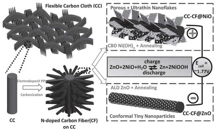 | ||
| Fig. 22 Pictorial representation of the fabrication procedure of a flexible Ni–Zn battery with 3D hierarchical NiO and ZnO coated on CFs with N-doping on CC as the electrodes. Reproduced with permission from ref. 40. Copyright (2016), WILEY-VCH Verlag GmbH & Co. KGaA, Weinheim. | ||
A comparison on the CV curves of CC-CF@ZnO and CC-CF@NiO electrodes obtained at 5 mV s−1 where the electrodes exhibit a pair of redox peaks are shown in Fig. 23(a). From these curves, it can be observed that a high-voltage battery can be fabricated using these two electrodes where CC-CF@NiO serve as the positive electrode and CC-CF@ZnO serve as the negative electrode. The authors os this work have fabricated a battery using these electrodes utilizing 2 M KOH/ZnO aqueous electrolyte. They have also constructed a flexible battery using PVA-KOH/ZnO polymer gel electrolyte. The CV curves obtained at two different scan rates, such as 5 and 10 mV s−1 for the battery utilizing 2 M KOH/ZnO aqueous electrolyt are depicted in Fig. 23(b). The charge/discharge curves obtained for battery at different current densities ranging from 0.5 to 20 mA cm−2 are shown in Fig. 23(c). The charge/discharge curves demonstrates that each curve exhibit charge and discharge plateaus between 1.85 and 1.75 V, which consists of hysteresis with a small voltage drop of 0.1 V. Even by increasing the current density to 10 and 20 mA cm−2, the fabricated aqueous battery still maintained a capacity of 72 and 58.4%, respectively, indicating its efficient rate capability evident from Fig. 23(e). To demonstrate practical applications, a quasi-solid-state battery was fabricated using PVA-KOH polymer gel electrolyte. The charge/discharge curves of the fabricated battery at different current densities ranging from 0.5 to 10 mA cm−2 are shown in Fig. 23(d). In addition to the analysis performed for aqueous electrolytes, the charge/discharge plateau observed for the quasi-solid-state battery is comparable with voltage hysteresis. This is due to high charge transfer resistance and diffusion resistance since the polymer gel electrolyte was employed. With an increase in the current density, the quasi-solid-state battery exhibited low capacity than the one using an aqueous electrolyte (Fig. 23(e)).
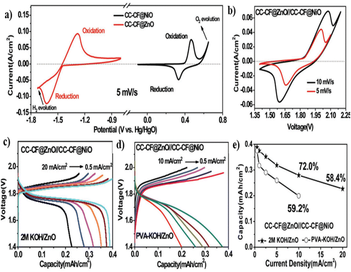 | ||
| Fig. 23 (a) CV curves of CC-CF@NiO and CC-CF@ZnO electrodes obtained at a constant scan rate of 5 mV s−1, (b) CV curves at two different scan rates and (c) charge/discharge curves at different current densities of an aqueous Ni–Zn battery utilizing 2 M KOH/ZnO electrolyte, (d) charge/discharge curves at different current densities of the flexible Ni–Zn battery utilizing PVA-KOH/ZnO polymer gel electrolyte, and (e) comparison on the rate performance of two Ni–Zn batteries fabricated using two different electrolytes: 2 M KOH/ZnO aqueous electrolyte and PVA-KOH/ZnO polymer gel electrolyte. Reproduced with permission from ref. 40. Copyright (2016), WILEY-VCH Verlag GmbH & Co. KGaA, Weinheim. | ||
Numerous studies have been conducted on CF-based electrode fabrication for application in rechargeable batteries. More details about the reports corresponding to CF-based batteries utilizing different electrodes, their preparation and performance characteristics are depicted in Table 1.
| Electrode | Battery type | Synthesis method | Major observation | Ref. |
|---|---|---|---|---|
| Ni-metal organic framework (MOF)-74 grown on CNTfs | Ni–Zn battery | Solvothermal method | • Device assembled to a higher discharge voltage of 1.75 V | 41 |
| • Reversible capacity of 184.5 mA h cm−3 at 0.25 A cm−3 | ||||
| • 186.28 mW h cm−3 and a maximum power density of 8.4 W cm−3 | ||||
| 3D CC-ZnO@C–Zn | Zn–Co battery | In situ growth, followed by the deposition of Zn | • Higher energy density of 4.6 mW h cm−3 with a power density of 0.42 W cm−3 | 42 |
| • Capacitance retention of 82% after 1600 cycles | ||||
| CoOx encapsulated to carbonized microporous fiber | ZAB | Electrospinning of ZIF-67 with PAN | • Battery holds an initial open circuit voltage of 1.34 V in its flat state, and it reaches 1.33, 1.33 and 1.31 V at a bending angle of 60°, 90° and 120°, respectively | 43 |
| • Galvanostatic cycling at 5 mA cm−2 up to 12 h was found with a round-trip efficiency of 49% | ||||
| NiFe alloy anchored on N-doped CF derived from bamboo stick | ZAB | Delignification–impregnation–carbonization strategy | • Power density of 102 mW cm−2 and specific capacity of 729 mA h g−1 | 44 |
| • The device is cycled for about 150 h at 10 mA cm−2 | ||||
| Nanocube-like KNiFe(CN)6 (KNHCF) and rugby ball-like NaTi2(PO4)3 (NTP) are grown on carbon nanotube fibers as flexible cathode and NTP@CNTF as anode | SIB | Chemical bath deposition and chemical etching, followed by solvothermal method | • Higher capacity of 34.21 mA h cm−3 and energy density of 39.32 mW h cm−3 | 45 |
| • Prominent mechanical flexibility with only 5.7% capacity retention after bending it for 90° for 3000 cycles |
4. Challenges and future perspectives
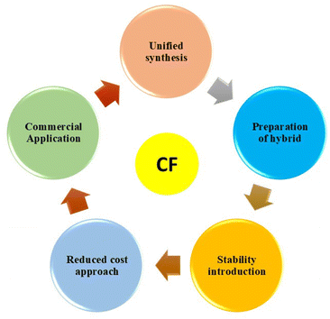
CFs are considered a promising future material by assembling them with energy storage devices to meet the requirements of the flexible and wearable electronic industry. From the present review, it is clear that these materials introduce excellent flexibility and device performance for the host materials that we use for device fabrication. It is possible to synthesize CF-based electrode material in a cost-effective, facile and eco-friendly way; therefore, we can develop the electronic devices in a feasible method. It is possible to develop a battery-type and capacitive-type material using CF by coating the prescribed material to the fiber substrate by applying simple drop-casting or spin-coating approaches. From the present study, we can find that the analysis of the performance of these fiber-based electrodes has been widely performed, but the device level applications have been less explored.The major challenges that stand as demerits to the exploration of CF-based materials in rechargeable batteries are depicted in Fig. 24 and described below:
• Lack of a unified synthesis approach is a major drawback to the exploration of CF-based rechargeable batteries. The rechargeable battery electrode should possess a well-defined architecture with uniform morphology for demonstration in practical application. Otherwise, it will suffer from deterioration of its performance in terms of morphological alteration after long-term use.
• The preparation of rechargeable battery electrode materials based on new-generation materials, such as layered materials and metal organic frameworks, is lacking in the literature. Using these battery-type electrode materials coated on a CF substrate will deliver excellent performance characteristics. Few reports in this field destroy the practical device demonstration of CF-based materials.
• Most synthesis methods based on CF use high-cost approaches. However, we need a unified synthesis at a reduced cost, especially from biomass-based materials. These biomass materials are highly available in the literature, and we can extract them in a low-cost manner without using any hard procedures.
• Another demerit underlying the application of CF-based materials is their reduced stability for long-term use. Some stability issues have been reported for CF-based ones due to oxidation, reduction in modulus strength, etc. Therefore, it is very important to incorporate stability by inserting guest species, optimizing the synthesis approach, etc.
It is noteworthy here that all the above-mentioned demerits/challenges related to the manufacturing process of CF-based rechargeable batteries affect their possible commercialization. For potential commercialization and acceptance in the market, low-cost rechargeable batteries should be developed, which necessitates a low-cost and scalable preparation route along with suitable electrode materials. The application of new-generation electrode-active materials, such as layered transition metal dichalcogenides,46,47 MXenes,48,49 and graphitic-carbon nitride,50,51 in the preparation of CF-based electrodes is highly recommended to increase their charge storage potential for commercial batteries, in which CF functions either as a substrate material or an additive. Custom-made low-cost CF-based flexible rechargeable batteries may boost the marketability of wearable electronic gadgetries in the near future. Therefore, we need a deep level study for the demonstration of these fiber-based electrodes to meet the requirements of device demonstrations, such as in the field of telecommunication and health-monitoring systems. Thus, further development using CF for practical device applications is necessary, and it is sure that we can achieve it in the near future.
5. Conclusions
We provided a detailed review of the CF-based fibrous electrodes for flexible battery application. CF is considered a promising sustainable material for electrochemical energy storage applications, and it functions as a substratum, an electrode-active material or an additive material for application in rechargeable batteries. Different carbon materials, such as mesoporous carbons, activated carbons, CNTs, and graphene, can be combined with CF-based electrodes to achieve high performance, as they can act as large surface areas providing electronically conducting templates. CF can be considered a fantastic sustainable material for developing sustainable rechargeable batteries for a greener future. To meet the demand for ever-growing flexible and wearable electronic gadgetries, developing flexible and wearable electrochemical energy storage devices is not just a requirement but a necessity. In this review, we discussed recent developments in sustainable CF-based fibrous electrodes for application in various rechargeable batteries. The strategies to prepare CF-based flexible electrodes for flexible batteries were discussed using schematic diagrams. The various synthetic approaches opted for the synthesis, such as spray coating, dip coating, and electrochemical deposition, were explained in detail. The electrochemical performance evaluation of carbon-based fibrous electrodes for batteries was examined using various electrochemical tools, such as CV, galvanostatic charge/discharge measurement, and electrochemical impedance spectroscopy. This review demonstrates the development of flexible batteries using sustainable CF-based fibrous electrodes.Data availability
Data sharing not applicable – no new data generated.Conflicts of interest
The authors declare no potential conflict of interest.References
- S. A. Thomas and J. Cherusseri, A Review of Nb2CT x MXene as an Emerging 2D Material: Synthesis, Applications in Rechargeable Batteries and Supercapacitors, Progress, and Outlook, Energy Fuels, 2023, 37(11), 7555–7576 Search PubMed
.
- M. Farghali, A. I. Osman, I. M. A. Mohamed, Z. Chen, L. Chen, I. Ihara, P.-S. Yap and D. W. Rooney, Strategies to save energy in the context of the energy crisis: a review, Environ. Chem. Lett., 2023, 21(4), 2003–2039 Search PubMed
.
- R. Aryee, The Sustainability Onion: A panoramic view of a parent concept, its paths, and progeny, RSC Sustainability, 2024, 2, 1948–1962 Search PubMed
.
- S. A. Thomas, J. Cherusseri and D. N. Rajendran, Recent Advancements on Carbon Fibers-Based Sustainable Electrodes for Flexible and Wearable Supercapacitors, RSC Sustainability, 2024, 2, 2403–2443 Search PubMed
.
- A. C. Rolandi, I. de Meatza, N. Casado, M. Forsyth, D. Mecerreyes and C. Pozo-Gonzalo, Unlocking sustainable power: advances in aqueous processing and water-soluble binders for NMC cathodes in high-voltage Li-ion batteries, RSC Sustainability, 2024, 2, 2125–2149 Search PubMed
.
- S. A. Thomas and J. Cherusseri, Recent Advances in Synthesis and Properties of Zirconium-Based MXenes for Application in Rechargeable Batteries, Energy Storage, 2023, 5, e475 Search PubMed
.
- M. A. A. M. Abdah, J. Cherusseri, N. A. Dzulkarnain, M. Mokhtar, M. S. Su’ait, Y. S. Tan, M. N. Mustafa, M. Khalid, A. Numan and A. Radwan, Facile synthesis of microwave-etched Ti3C2 MXene/activated carbon hybrid for lithium-ion battery anode, J. Electroanal. Chem., 2023, 928, 117050 Search PubMed
.
- T. Kim, W. Song, D.-Y. Son, L. K. Ono and Y. Qi, J. Mater. Chem. A, 2019, 7, 2942–2964 Search PubMed
.
- C. M. Subramaniyam, K. A. Deshmukh, Z. Tai, N. Mahmood, A. D. Deshmukh, J. B. Goodenough, S. X. Dou and H. K. Liu, 2D layered graphitic carbon nitride sandwiched with reduced graphene oxide as nanoarchitectured anode for highly stable lithium-ion battery, Electrochim. Acta, 2017, 237, 69–77 Search PubMed
.
- S. A. Thomas, J. Cherusseri and D. N. Rajendran, Strategically-Designed Hierarchical Polypyrrole-Modified Manganese-Doped Tin Disulfide (SnS2) Nanocomposite Electrodes for Supercapatteries with High Specific Capacity, Electrochim. Acta, 2024, 504, 144910 Search PubMed
.
- N. Yabuuchi, K. Kubota, M. Dahbi and S. Komaba, Research development on sodium-ion batteries, Chem. Rev., 2014, 114(23), 11636–11682 Search PubMed
.
- S. A. Thomas, J. Cherusseri and D. N. Rajendran, Hierarchical Two-Dimensional Layered Nickel Disulfide (NiS2)@ PEDOT: PSS Nanocomposites as Battery-Type Electrodes for Battery-Type Supercapacitors with High Energy Density, Electrochem, 2024, 5(3), 298–313 Search PubMed
.
- J. R. Klaehn, M. Shi, L. A. Diaz, D. E. Molina, R. Repukaiti, F. M. Sani, M. Lencka, A. Anderko, N. Arulsamy and T. E. Lister, Fractional precipitation of Ni and Co double salts from lithium-ion battery leachates, RSC Sustainability, 2024, 2, 3298–3310 Search PubMed
.
- S. A. Thomas, J. Cherusseri and D. N. Rajendran, Nickel Disulfide (NiS2): A Sustainable Low-Cost Electrode Material for High-Performance Supercapacitors, Energy Technol., 2024, 12(7), 2400138 Search PubMed
.
- S. A. Thomas and J. Cherusseri, Boron Carbon Nitride (BCN): Emerging Two-Dimensional Nanomaterial for Supercapacitors, J. Mater. Chem. A, 2023, 11, 23148–23187 Search PubMed
.
- Q. Ren, Y. Yuan and S. Wang, Interfacial strategies for suppression of Mn dissolution in rechargeable battery cathode materials, ACS Appl. Mater. Interfaces, 2021, 14(20), 23022–23032 Search PubMed
.
- S. A. Thomas, Layered two-dimensional black phosphorous-based hybrid electrodes for rechargeable batteries, J. Energy Storage, 2023, 73, 109068 Search PubMed
.
- G. Scandurra, A. Arena and C. Ciofi, A brief review on flexible electronics for IoT: Solutions for sustainability and new perspectives for designers, Sensors, 2023, 23(11), 5264 Search PubMed
.
- W. Heng, S. Solomon and W. Gao, Flexible electronics and devices as human–machine interfaces for medical robotics, Adv. Mater., 2022, 34(16), 2107902 Search PubMed
.
- S. Majumder, T. Mondal and M. J. Deen, Wearable sensors for remote health monitoring, Sensors, 2017, 17(1), 130 Search PubMed
.
- B. De, A. Yadav, S. Khan and K. K Kar, A facile methodology for the development of a printable and flexible all-solid-state rechargeable battery, ACS Appl. Mater. Interfaces, 2017, 9(23), 19870–19880 Search PubMed
.
- S. Ghosh, U. Bhattacharjee, S. Patchaiyappan, J. Nanda, N. J. Dudney and S. K. Martha, Multifunctional Utilization of Pitch-Coated Carbon Fibers in Lithium-Based Rechargeable Batteries, Adv. Energy Mater., 2021, 11(17), 2100135 Search PubMed
.
- J. Cherusseri and K. K. Kar, Recent progress in nanocomposites based on carbon nanomaterials and electronically conducting polymers, Polym. Nanocompos. Inorg. Org. Nanomater., 2015, 229–256 Search PubMed
.
- Z. Hou, B. Zhu, G. Li, P. Wang, C. Meng, S. Guo, C. Liu and S. Fan, Nanostructured Co3O4 Asymmetrically Deposited on a Single Carbon Cloth for an All-Solid-State Integrated Hybrid Device with Reversible Zinc-Air High-Energy Conversion and Asymmetric Supercapacitive High-Power Delivery, Energy Fuels, 2021, 35(15), 12706–12717 Search PubMed
.
- A. Pendashteh, J. Palma, M. Anderson, J. J. Vilatela and R. Marcilla, Doping of self-standing cnt fibers: promising flexible air-cathodes for high-energy-density structural zn–air batteries, ACS Appl. Energy Mater., 2018, 1(6), 2434–2439 Search PubMed
.
- K. Wang, X. Zhang, J. Han, X. Zhang, X. Sun, C. Li, W. Liu, Q. Li and Y. M., High-performance cable-type flexible rechargeable Zn battery based on MnO2@ CNT fiber microelectrode, ACS Appl. Mater. Interfaces, 2018, 10(29), 24573–24582 Search PubMed
.
- Y. D. Yücel, D. Zenkert, W. R. Lindström and G. Lindbergh, LiFePO4-coated carbon fibers as positive electrodes in structural batteries: Insights from spray coating technique, Electrochem. Commun., 2024, 160, 107670 Search PubMed
.
- J. Marchewka, E. Kołodziejczyk, P. Bezkosty and M. Sitarz, Characterization of electrochemical deposition of copper and copper (I) oxide on the carbon nanotubes coated stainless steel substrates, Sci. Rep., 2023, 13(1), 6786 Search PubMed
.
- X. Wang, X. Zhao, W. Wang, J. Zhang, L. Zhang, F. He and J. Yang, Controllable preparation of a nano-hydroxyapatite coating on carbon fibers by electrochemical deposition and chemical treatment, Mater. Sci. Eng., C, 2016, 63, 96–105 Search PubMed
.
- D. Tonelli, E. Scavetta and I. Gualandi, Electrochemical deposition of nanomaterials for electrochemical sensing, Sensors, 2019, 19(5), 1186 Search PubMed
.
- X. Tang and X. Yan, Dip-coating for fibrous materials: mechanism, methods and applications, J. Sol-Gel Sci. Technol., 2017, 81, 378–404 Search PubMed
.
- D. Petrushenko, Z. Rahmati, D. Barazanchy, W. De Backer, W. E. Mustain, R. E. White, P. Ziehl and P. T. Coman, Dip-coating of carbon fibers for the development of lithium iron phosphate electrodes for structural lithium-ion batteries, Energy Fuels, 2023, 37(1), 711–723 Search PubMed
.
-
M. D. Banea, L. F. da Silva, and R. D. Campilho, Principles of adhesive bonding, Joining of Polymer-Metal Hybrid Structures: Principles and Applications, John Wiley & Sons, Inc., 2018, pp. 3–27 Search PubMed
.
- H. Yin, X.-X. Yu, Y.-W. Yu, M.-L. Cao, H. Zhao, C. Li and Z. Ming-Qiang, Tellurium nanotubes grown on carbon fiber cloth as cathode for flexible all-solid-state lithium-tellurium batteries, Electrochim. Acta, 2018, 282, 870–876 Search PubMed
.
- Y. Wang, R. Gan, S. Zhao, W. Ma, X. Zhang, Y. Song, C. Ma and J. Shi, B, N, F tri-doped lignin-derived carbon nanofibers as an efficient metal-free bifunctional electrocatalyst for ORR and OER in rechargeable liquid/solid-state Zn-air batteries, Appl. Surf. Sci., 2022, 598, 153891 Search PubMed
.
- C. Liu, Q. Li, J. Cao, Q. Zhang, P. Man, Z. Zhou, C. Li and Y. Yao, Superstructured α-Fe2O3 nanorods as novel binder-free anodes for high-performing fiber-shaped Ni/Fe battery, Sci. Bull., 2020, 65(10), 812–819 Search PubMed
.
- Q. Yong, M. Chen, J. He and X. Dong, A lightweight 3D Zn@ Cu nanosheets@ activated carbon cloth as long-life anode with large capacity for flexible zinc ion batteries, J. Power Sources, 2020, 480, 228871 Search PubMed
.
- D. Ji, S. Peng, D. Safanama, H. Yu, L. Li, G. Yang, X. Qin, M. Srinivasan, S. Adams and S. Ramakrishna, Design of 3-dimensional hierarchical architectures of carbon and highly active transition metals (Fe, Co, Ni) as bifunctional oxygen catalysts for hybrid lithium–air batteries, Chem. Mater., 2017, 29(4), 1665–1675 Search PubMed
.
- T. Du, H. Zhu, B. B. Xu, C. Liang, M. Yan and Y. Jiang, A universal strategy to fabricate metal sulfides@ carbon fibers as freestanding and flexible anodes for high-performance lithium/sodium storage, ACS Appl. Energy Mater., 2019, 2(6), 4421–4427 Search PubMed
.
- J. Liu, C. Guan, C. Zhou, Z. Fan, Q. Ke, G. Zhang, C. Liu and J. Wang, A flexible quasi-solid-state nickel–zinc battery with high energy and power densities based on 3D electrode design, Adv. Mater., 2016, 28(39), 8732–8739 Search PubMed
.
- P. Man, B. He, Q. Zhang, Z. Zhou, C. Li, Q. Li, L. Wei and Y. Yao, A one-dimensional channel self-standing MOF cathode for ultrahigh-energy-density flexible Ni–Zn batteries, J. Mater. Chem. A, 2019, 7(48), 27217–27224 Search PubMed
.
- M. Li, J. Meng, Q. Li, M. Huang, X. Liu, K. A. Owusu, Z. Liu and L. Mai, Finely Crafted 3D Electrodes for Dendrite-Free and High-Performance Flexible Fiber-Shaped Zn–Co Batteries, Adv. Funct. Mater., 2018, 28(32), 1802016 Search PubMed
.
- C. Yang, Y. Li, B. Zhang, Y. Lian, Y. Ma, X. Zhao, X. Zeng, J. Li, Z. Deng, J. Ye, W. Wu and Y. Peng, Nitrogen-doped carbon fibers embedding CoOx nanoframes towards wearable energy storage, Nanoscale, 2020, 12(16), 8922–8933 Search PubMed
.
- Y. Niu, X. Teng, S. Gong and Z. Chen, A bimetallic alloy anchored on biomass-derived porous N-doped carbon fibers as a self-supporting bifunctional oxygen electrocatalyst for flexible Zn–air batteries, J. Mater. Chem. A, 2020, 8(27), 13725–13734 Search PubMed
.
- B. He, P. Man, Q. Zhang, H. Fu, Z. Zhou, C. Li, Q. Li, L. Wei and Y. Yao, All binder-free electrodes for high-performance wearable aqueous rechargeable sodium-ion batteries, Nano-Micro Lett., 2019, 11(1), 1–12 Search PubMed
.
- S. A. Thomas, J. Cherusseri and D. N. Rajendran, 2D Nickel Sulfide Electrodes with Superior Electrochemical Thermal Stability along with Long Cyclic Stability for Supercapatteries, Energy Technol., 2024, 2301641 Search PubMed
.
- E. Singh, P. Singh, K. S. Kim, G. Y. Yeom and H. S. Nalwa, Flexible molybdenum disulfide (MoS2) atomic layers for wearable electronics and optoelectronics, ACS Appl. Mater. Interfaces, 2019, 11(12), 11061–11105 Search PubMed
.
- M. Zaed, K. H. Tan, R. Saidur, A. K. Pandey and J. Cherusseri, Low-cost synthesis of Ti3C2Tx MXene-based sponge for solar steam generation and clean water production, Ceram. Int., 2024, 50, 27910–27922 Search PubMed
.
- S. Asad, A. Zahoor, F. A. Butt, S. Hashmi, F. Raza, I. Ul Ahad, J. Hakami, S. Ullah, A. Al-Ahmed, F. Khan and M. Christ, Recent Advances in Titanium Carbide MXene (Ti3C2Tx) Cathode Material for Lithium–Air Battery, ACS Appl. Energy Mater., 2022, 5(10), 11933–11946 Search PubMed
.
-
S. A. Thomas, J. Cherusseri, D. N. Rajendran and R. Saidur, Graphitic Carbon Nitride and Their Derivatives, in Handbook of Functionalized Carbon Nanostructures: from Synthesis Methods to Applications, Springer, 2024, pp. 1–38 Search PubMed
.
- M. Inagaki, T. Tsumura, T. Kinumoto and M. Toyoda, Graphitic carbon nitrides (g-C3N4) with comparative discussion to carbon materials, Carbon, 2019, 141, 580–607 Search PubMed
.
| This journal is © The Royal Society of Chemistry 2025 |


