 Open Access Article
Creative Commons Attribution 3.0 Unported Licence
Concentration gradient generation methods based on microfluidic systems
Xiang Wang
 ,
Zhaomiao Liu
 * and
Yan Pang

College of Mechanical Engineering and Applied Electronics Technology, Beijing University of Technology, Beijing 100124, China. E-mail: lzm@bjut.edu.cn
First published on 9th June 2017
Abstract
Various concentration gradient generation methods based on microfluidic systems are summarized in this paper. The review covers typical structural characteristics, gradient generation mechanisms, theoretical calculation formulas, applicable scopes, and advantages and disadvantages of these approaches in detail. According to the type of reagents involved, these methods are classified into mono-phase methods and multi-phase methods, both of which can be implemented by alternative protocols, while the latter methods particularly refer to droplet-based platforms. For mono-phase methods, the shearing effect would be presented if there are flowing streams in the gradient generation channel. Therefore, the generation speed of channels with moving liquids is relatively fast, which is suitable for dynamic gradients but accompanied by shearing as well, while channels without flowing streams would avoid shearing but are prone to static gradient generation determined by the low speed. Newly developed droplet-based generation systems could provide isolated droplets to avoid the disturbances from the outside continuous phase, however, they require precise droplet generation and control modules. Thereby the most suitable platform can be chosen according to the specific application, while the advantages of different methods could be combined to evade the defects and improve the precision of a single structure.
1. Introduction
At the fundamental level, cells in living organisms are surrounded by microenvironments of different chemical concentration gradients, which play an important role in biological phenomena including development, inflammation, cancer metastasis, drug delivery and wound healing.1,2 Research into the interplay between molecular gradients and corresponding cellular responses may improve the understanding of the underlying mechanisms of human body function.3–7 By precisely recreating in vivo concentration gradients, various cellular responses of migration, differentiation and resistance can be simulated by in vitro systems.8–14 Besides, the assays involving activity, efficiency or toxicity usually need molecular concentration gradients,15,16 such as toxicity assessment of heavy metals,17 detection of enzymatic kinetics,18,19 in vitro expression of proteins,20 etc.Alternative methods have been proposed to generate concentration gradients for in vitro biochemical reactions and lots of cellular response principles have been revealed.21 However, with the development of biochemical studies, several requirements on concentration gradients are raised which cannot be resolved technically by traditional macroscale methods.22 Firstly, concentration gradients of both small characteristic scale and high precision are requested. Since diameters of most cells range from 1 to 100 μm and lengths of intercellular signals are approximately 250 μm,21 the large characteristic length of concentration gradients generated by conventional non-microfluidic systems cannot accurately achieve the control and detection at the single-cell level.23 Traditional cultures also require relatively large volumes of media, which is not applicable for costly growth factors and other scarce reagents.24 Operations in manual mode or by robotics are usually time-consuming and labor intensive.25 Secondly, concentration gradients with specific and complex shapes are needed to stimulate the specific reactions. For example, the bacteria migration shows variations of chemotactic responses when chemoattractant gradients are changed and cancerous cells migrate in nonlinear chemotactic gradients but do not respond to linear gradients.26–28 Thirdly, both static molecular gradients of long-term stability and dynamic gradients with quick response are required. For traditional platforms, molecules diffuse in all directions without limitation, leading to the inability to keep static molecular gradients for a long time29 or to accurately tune dynamic gradients without delay.30 As a consequence, the observation and determination of intracellular dynamics or population behaviors that need temporally varying stimulus patterns are restricted.31
The above requirements which cannot be met by traditional generation platforms could be satisfied by microfluidic-based generators with their precise fluid control. Particularly, molecular gradient generation methods based on microfluidic systems have advantages of small characteristic scale that is suitable for detections at the single-cell level,32–34 low reagent assumptions that greatly reduce sample costs,35,36 great controllability to generate long-term stable static gradients and quickly responsive dynamic gradients while maintaining their resolutions,37–39 great compatibility to be directly utilized to various biochemical applications as quite a lot of devices are fabricated entirely or mainly by PDMS (polydimethylsiloxane).24,40–42 Moreover, well-established device fabrication methods based on multilayer soft-lithography largely increase the flexibility and functionality of microfluidic structures10,43 as well as cut the economic and time costs.44 Parallel operations by combining multiple junctions further improve the efficiency and throughput of microfluidic systems.45,46
Due to its huge advantages, the microfluidic technology has been widely applied and alternative microfluidic-based platforms have been devised for the concentration gradient generation. The obtained gradients are predictable and reproducible, while controllable and quantifiable at the same time. Based on the used liquid phases, this paper classifies the microfluidic-based systems into the mono-phase methods and the multi-phase methods, while the latter type particularly refers to the droplet-based methods. By analyzing the typical structures and working principles as well as comparing the advantages and disadvantages of each method, the applicable scope and corresponding improvements are summarized. Moreover, the idea for future design of microfluidic systems is proposed.
2. Concentration gradient generation methods based on microfluidic systems
Concentration gradient generation methods based on microfluidic systems are classified into two patterns, mono-phase methods and droplet-based methods. The mono-phase methods are further separated into two groups, based on the presence of the shearing which is caused by flowing streams in the gradient generation channel. Meanwhile, droplet-based microfluidic systems could provide isolated chambers due to the interface and the inside reagents are protected from the outside shearing. Though vortices of the isolated dispersed phase may still cause weak shearing, depending on the internal flow field,47–49 droplet-based systems are generally considered as methods without shearing. Therefore, in order to meet the requirements of specific applications, it's feasible to choose the device junction according to the typical structure and working principle of each method shown in Table 1 as well as determine the initial conditions of flow rates and concentrations of the used reagents by corresponding theoretical calculations.2.1 Mono-phase methods with shearing
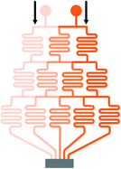
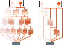
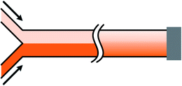
Mono-phase methods with shearing include tree-shape networks and Y-shape junctions. Concentration gradients by tree-shape networks are obtained after a series of splitting, combining and mixing, which mainly rely on the hydrodynamic resistance ratios of bypass channels. Whereas Y-shape junctions directly take advantage of the molecular diffusion between concentrated reagents and dilute liquids. Typically, two or three inlets are designed, from which liquids with different initial concentrations are flowed into the device. During the flowing process along internal channels, the injected reagents exchange solute molecules to generate more molecular concentrations. Hence, gradient profiles are developed with gradually decreasing step differences between any two adjacent streams. In addition, as fresh reagents are renewed and waste liquids are drained continuously, spatially and temporally constant concentrations can be maintained with stable inlet flow conditions.50The tree-shape network is a typical practice of pressure-driven systems.53 For a better understanding, the tree-shape network is usually considered as an analogy to the electronic circuit plotted in Fig. 1, where the pressure drop ΔP, volumetric flow rate Q and hydraulic resistance R correspond to the voltage drop, current and electric resistance, respectively.53,54 Analogous to Ohm's law, the Hagen–Poiseuille's law ΔP = RQ can be deduced. When the pressure drop and channel cross-section of each stage are equal, the hydrodynamic resistance of a channel is proportional to its own length, R ∝ L. Therefore, the branch length ratio and the splitting ratio can be resolved by each other with Q1/Q2 = R2/R1 = L2/L1, while the mixing efficiency has to be taken into consideration for further determining the specific lengths of branch channels. As indicated by numerical simulations, a critical channel length exists corresponding to each flow rate in order to guarantee enough diffusive time for complete mixing.55,56 The channel length should be larger than the critical value for the designed flow rate or the flow rate should be kept within the specific range for the defined channel length. Besides, mixing could be achieved within a relatively short distance when micro-mixers are added.42,57–59
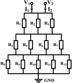 | ||
| Fig. 1 The equivalent electronic circuit model of the tree-shape network shown in Table 1. | ||
In practice, shapes of the concentration gradient profile that a tree-shape network could provide are closely associated with the inlet number. When only two inlets are included, intermediate values between two neighboring concentrations are generated whatever the splitting ratios are and thus the gradient profile is always kept monotonous. As the number of inlets increases, gradients of more complex shapes can be yielded.60,61 To be more precise, gradient profiles generated by a microfluidic device having n inlets could be described empirically by a polynomial of (n − 1)th order.28 Another way to generate complex concentration gradient profiles is by combining several simple tree-shape networks in a parallel way and a broad range of shapes like the sawtooth62 and N-shape63 can be obtained.
Though generated by different tree-shape networks, the resulting molecular gradients are applied in several similar ways. Individual branches with liquids of varied uniform concentrations can be directly applied for the fabrication of particles or fibers,57,64,65 as well as the culture and detection of cells or DNA.66–69 Under more occasions, these branch streams are recombined into a wider chamber to form a solution with the entire molecular gradient profile.51,70–72 The resolutions of the molecular gradients are determined by the number of branches as more branches leading to higher resolutions.71 With the molecular diffusion between adjacent streams, step differences of concentrations gradually disappear and thus step gradient profiles develop into smooth profiles along the way.73–76 The flowing process in the wider chamber is similar to Y-shape junctions introduced later. However, shearing is introduced meanwhile which may cause differences to the response of the detected analytes or even damages for cases where the shear stress is not present in their original in vivo environments.77 Zheng et al.17 added diffusion channels between individual channels and the culture chamber, thus protecting the chamber environment from shearing. An array of parallel micro-wells within the culture area was designed by Wang et al.63 and the flow velocity in the wells was reduced significantly. Simulation results demonstrated that the shear stress was effectively decreased from a high level to nearly zero.
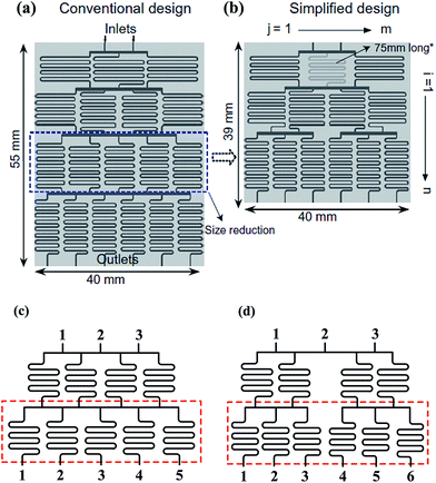 | ||
| Fig. 2 Comparisons of a tree-shape network and the simplified design. (a) A tree-shape network and its overall geometrical sizes. (b) A simplified design of the tree-shape network in (a) and the reduced overall sizes (reproduced from ref. 82 with permission from Elsevier). (c) and (d) Partial enlargements of the splitting network in (a) and (b), respectively. Note that the simplified network in (b) obtains six concentrations in three stages as compared to four stages in (a). | ||
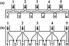 | ||
| Fig. 3 Comparisons of the schematic diagrams of a tree-shape network and another altered design (reproduced from ref. 29 with permission from the Royal Society of Chemistry). Splitting and recombination processes of the streams in (a) a tree-shape network, and (b) an altered tree-shape network, respectively, with arrows indicating the flow direction of branch streams. The confined space of horizontal microchannel in (a) determines that a stream can only be split to the left and right sides, while the wide chamber in (b) allows a stream to be separated into branches. | ||
Limited by the flow space, above mentioned one-layer networks can only split and combine streams from neighboring channels while multi-layer networks allow channels to pass over one another, resulting in more flexible patterns to control the streams. Neils et al.84 proposed a system in four flow levels and obtained 16 combinations of two dye solutions, which could not be obtained easily in single-layer networks. Lee et al.7 presented a hybrid of two different tree-shape junctions which were designed in separate layers. This network is capable of combining multiple concentrations of two different variance profiles determined by the channel network in each layer. Multi-layer networks significantly reduce the number of the dilution stages which minimizes errors accumulated from previous serial dilution steps as well as reduces the footprint occupied by the device and the required resources correspondingly. Nevertheless, the advantages of the three-dimensional network are achieved with the compromise of design complexity and fabrication cost.
According to the Fick's law, molecular transport from diffusion is related to the initial source concentrations and diffusive time, while the latter one is determined by the flow rate and flow distance within microchannels.85,96 To be more specific, the concentration difference between two outermost sides decreases and the shape of the gradient profile flattens with longer diffusive time, that is, smaller flow rate or longer flow distance with the other parameter fixed.87,92,97 Firstly, with the same flow distance, molecules transport a relatively short transverse distance with larger flow rate, resulting in concentration gradients of steeper slope.98 And molecules from one reagent would not reach the other side of the channel until the flow rate decreases to a critical value.95,99,100 Secondly, the molecular gradients measured at different downstream distances are varied when the flow conditions are maintained stable. As illustrated in Fig. 4(b), the slope of the gradient is steep at the intersection point of two streams while the profile becomes smooth far downstream.101,102 Therefore, the flow rate of the fluids and the position of the detection chamber need to be set properly.
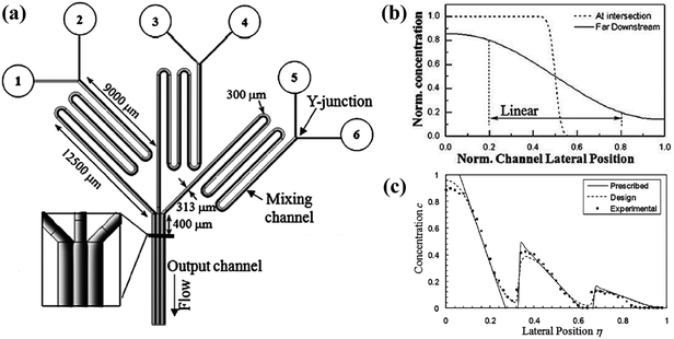 | ||
| Fig. 4 The schematic diagram of a gradient generator and the obtained gradient profiles. (a) A concentration gradient generator consisted of three Y-shape junctions in parallel. The black line 400 μm downstream of the intersection point shows the position where gradients are measured. (b) Comparisons of the gradient profiles measured at two positions of a Y-shape junction. (c) A sawtooth-shape concentration gradient generated by the device shown in (a). All concentrations in (b) and (c) are normalized. (Reproduced from ref. 100 with permission from the Royal Society of Chemistry). | ||
In fact, the central part of the gradient profile between any two liquids is always linear. Complex concentration gradients can be obtained by increasing the inlet number and altering the combination of initial concentrations or integrating several simple junctions (as shown in Fig. 4(a)).99 As shown in Fig. 4(c), the slopes and endpoint values of each part of the integrated profile are varied while the central regions between endpoints are also linear.97,100,103 Besides, when the inlet number is increased to three, the position of the interface between adjacent streams can be altered by adjusting the relative inlet flow rates and the width of the middle stream can thus be controlled.97,104–106 As shown in Fig. 5(b), the width of the middle stream is decreased from 90 to 5 μm when the flow rate ratio of the three inlets is changed from 2![[thin space (1/6-em)]](https://www.rsc.org/images/entities/char_2009.gif) :
:![[thin space (1/6-em)]](https://www.rsc.org/images/entities/char_2009.gif) 1
1![[thin space (1/6-em)]](https://www.rsc.org/images/entities/char_2009.gif) :
:![[thin space (1/6-em)]](https://www.rsc.org/images/entities/char_2009.gif) 2 to 10
2 to 10![[thin space (1/6-em)]](https://www.rsc.org/images/entities/char_2009.gif) :
:![[thin space (1/6-em)]](https://www.rsc.org/images/entities/char_2009.gif) 1
1![[thin space (1/6-em)]](https://www.rsc.org/images/entities/char_2009.gif) :
:![[thin space (1/6-em)]](https://www.rsc.org/images/entities/char_2009.gif) 10.89 This method could be applied to assays of the single-cell level.89,91,107,108
10.89 This method could be applied to assays of the single-cell level.89,91,107,108
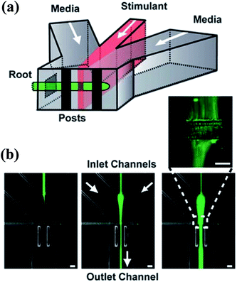 | ||
Fig. 5 The schematic diagram of a gradient generator and the obtained fluorescence images. (a) A Y-shape junction with three inlets. (b) Three fluorescence images obtained by the junction in (a) with different flow rates. The total flow rate is 200 μL min−1 and the flow rate ratios of the three inlets are (from left to right): 10![[thin space (1/6-em)]](https://www.rsc.org/images/entities/char_2009.gif) : :![[thin space (1/6-em)]](https://www.rsc.org/images/entities/char_2009.gif) 1 1![[thin space (1/6-em)]](https://www.rsc.org/images/entities/char_2009.gif) : :![[thin space (1/6-em)]](https://www.rsc.org/images/entities/char_2009.gif) 10, 5 10, 5![[thin space (1/6-em)]](https://www.rsc.org/images/entities/char_2009.gif) : :![[thin space (1/6-em)]](https://www.rsc.org/images/entities/char_2009.gif) 1 1![[thin space (1/6-em)]](https://www.rsc.org/images/entities/char_2009.gif) : :![[thin space (1/6-em)]](https://www.rsc.org/images/entities/char_2009.gif) 5, 2 5, 2![[thin space (1/6-em)]](https://www.rsc.org/images/entities/char_2009.gif) : :![[thin space (1/6-em)]](https://www.rsc.org/images/entities/char_2009.gif) 1 1![[thin space (1/6-em)]](https://www.rsc.org/images/entities/char_2009.gif) : :![[thin space (1/6-em)]](https://www.rsc.org/images/entities/char_2009.gif) 2 (left 2 (left![[thin space (1/6-em)]](https://www.rsc.org/images/entities/char_2009.gif) : :![[thin space (1/6-em)]](https://www.rsc.org/images/entities/char_2009.gif) middle middle![[thin space (1/6-em)]](https://www.rsc.org/images/entities/char_2009.gif) : :![[thin space (1/6-em)]](https://www.rsc.org/images/entities/char_2009.gif) right stream). (Reproduced from ref. 89 with permission from the Royal Society of Chemistry). right stream). (Reproduced from ref. 89 with permission from the Royal Society of Chemistry). | ||
2.2 Mono-phase methods without shearing
Streams of gradient generation methods with shearing relatively flow fast and the concentration gradients are evolved in a relatively short span. However, shearing is introduced with the flowing fluids. Modifications are made by adding blocking structures into specific devices to reduce the imposed shear stress.17,35 In comparison, mono-phase systems without flow streams in the gradient chamber would be an alternative way for these specific applications, including membrane systems and pressure balance systems.109–111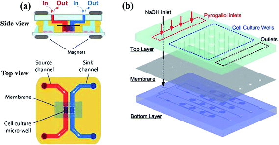 | ||
| Fig. 6 Examples of multi-layer concentration gradient generators of membrane systems. (a) The two layers are reversibly sealed across the membrane by magnets, with the gradient generated in the lower micro-well (reproduced from ref. 123 with permission from the Royal Society of Chemistry). (b) The chemical gradient is generated on the bottom layer and then diffuse into the culture array on the top layer through a PDMS membrane (reproduced from ref. 125 with permission from the Royal Society of Chemistry). | ||
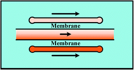
For single-layer designs, channels providing reagents and diluents are devised at each side of the gradient chamber while chemical molecules diffuse through the intermediate membrane, as shown in Table 1. The concentrations of the sources can be dispensed in advance before injection or produced by on-line chemical reactions. For example, Chen et al.113 introduced two sets of chemicals into the side channels for oxygen scavenging and oxygen generation, respectively, and concentrations of oxygen in the two channels were different. The porosity of PDMS membrane ensures the gas to diffuse through. As a result, the chemical gradient of oxygen is obtained in the middle chamber. Note that both the shape of middle chamber and the thickness of membrane have an influence on the gradient profile. Only linear gradients can be generated when straight channel is set as the middle chamber while complex gradient profiles like sawtooth-shape or bell-shape can be yielded by changing the shape of the middle chamber or by combining simple chambers.120 In fact, the endpoint values of gradient profiles are determined by concentrations of the source solutions and it is the variance ratios of profiles that are changed for different chambers.121,122 Meanwhile, it was confirmed by both numerical simulations and experiments that the diffusion rate slows down due to the increased resistance as the membrane thickness increases, resulting in concentration gradient profiles with reduced variance range and decreased steepness.117 Furthermore, flow rates of the injected fluids need to be kept above a critical value during the whole process of the gradient generation, otherwise molecular diffusion across the membrane dominates over the influx of the molecules into the side channels. Consequently, the chemical concentration decreases along the flow direction, causing the concentration gradient to vary along the channel at low flow rates.117
In multi-layer devices, the gradient chamber and the channels providing reagents and diluents can be designed at different layers and connected by the membrane, while the basic principles and the modification methods are the same as single-layer platforms.123–126 By taking advantaging of multi-layer systems, mono-phase generation methods with shearing introduced in Section 2.1 can also be improved. As shown in Fig. 6(b), the molecular concentration gradient is generated by flowing streams in the bottom layer. The environment of the gradient generation chamber in the top layer is thus protected from the shearing effect as separated from the flowing liquids by the membrane.37,125
It was presented by Abbott127 that there was big differences between 2-D cultures and 3-D cultures as antibodies against a cell-surface receptor completely changed the response behavior in 3-D cultures. Saadi et al.128 revealed that 3-D flow-free culture environment would be more physiologically relevant for specific cells that experience the shear stress in nature, while 2-D static culture could keep the autocrine and paracrine molecules which are washed away otherwise. The culture environment should be appropriate for the specific assays and comparisons between the two culture dimensions may be needed for studies involved normal tissues.
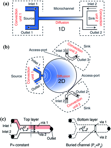 | ||
| Fig. 7 Single-layer and multi-layer pressure balance systems. (a and b) Single-layer systems that can generate one-dimensional and two-dimensional gradients, respectively (reproduced from ref. 131 with permission from the Royal Society of Chemistry). (c) A two-layer system which is connected by two vias that located at the same cross section (reproduced from ref. 134 with permission from the Royal Society of Chemistry). | ||
The pressure balance system can actually be considered as a combination of the convection system and the diffusion system. The input unit of the reagents and diluents is dominated by convection while only diffusion exists in the gradient generation chamber. Compared with each single mechanism, the hybrid system can yield gradients in a relatively fast way without shearing at the same time. This system provides a new idea to combine the advantages of various methods or structures in order to avoid the limit of a single one.
2.3 Droplet-based methods
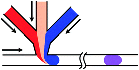
The droplet-based microfluidic systems have been widely studied and applied in recent years and the related techniques, including droplet generation, droplet coalescence, and droplet mixing, are developed in various applications.47,136–138 Though characteristics of droplet-based systems exhibit multiple aspects of complexity, well-designed manipulation of streams could lead to precise handling of small volumes of samples and quantitative analyses.139 Wrapped by the interface, droplets work as isolated chambers and the internal environments are protected from the outside disturbances, which could meet the requirements of chemical engineering and biochemical reactions.140–143 High-throughput generation also satisfies assays of large sample numbers.144 Moreover, special behaviors of the interface enable alternative control methods which can be applied for gradient generation in droplet arrays. The droplet-based methods are mainly divided into three types through droplet generation, droplet coalescence, and droplet dilution respectively. As droplets involved in most assays need to have the same volume, this paper only deals with droplets of the same sizes in one array.For multi-inlet junctions, altering the relative flow rates or concentrations of the loaded fluids is a straightforward method.152–155 The final concentrations of the droplets are varied correspondingly after mixing uniformly by serpentine channels.156,157 Theoretically any intermediate concentration values could be achieved by adjusting relative flow rates. However, flow rates of the pumped fluids may not be changed smoothly, leading to large polydispersity of the droplet size, and an associated dead volume may be introduced between transformations due to the response time of the pump.46,153 In comparison, altering the concentration of loaded reagents usually require active control.158 Zeng et al.159 developed a generation system with several separate aqueous inlets. By operations of desired pneumatic valves, droplets of various reagents were generated individually and selectively, as shown in Fig. 8(a). But this platform is not suitable for large numbers of inlets. Besides, the flow injection gradient technique (as shown in Fig. 8(b))25 or Taylor–Aris dispersion160 can also be coupled with droplet generation junctions. Mixtures with concentration gradients along the axial direction of the sample channel are obtained and then segmented into droplet sequences continuously. A similar droplet generation strategy was reported by Thakur et al.161 with the help of valve-controlled peristaltic pumps. Whereas the flowing manipulation is relatively complex or has moving parts and concentrations of the generated droplets cannot be readily predetermined.162
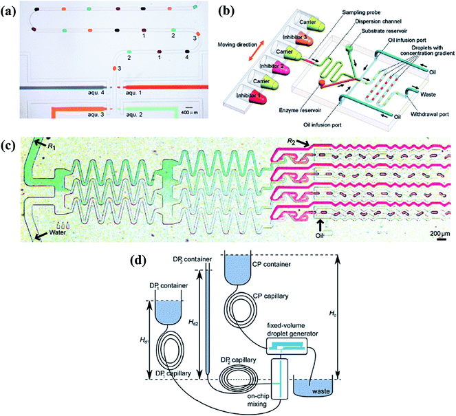 | ||
| Fig. 8 Droplet generation systems to obtain molecular gradients. (a) Individually and selectively operations of the associated pneumatic valves (reproduced from ref. 159 with permission from the Royal Society of Chemistry). (b) The flow injection gradient technique coupled with the flow-focusing junction (reproduced from ref. 25 with permission from American Chemical Society). (c) A tree-shape junction combined with flow-focusing junctions (reproduced from ref. 57 with permission from the Royal Society of Chemistry). (d) A fixed-volume droplet generator supplied by gravity driven systems (reproduced from ref. 169 with permission from American Institute of Physics). | ||
Changing the molecular concentration on-chip without external control would be an alternative method. Aforementioned tree-shape networks can be adopted to obtain various concentrations in parallel branches (as shown in Fig. 8(c)), which are used as inlets of the dispersed phase in a series of generation junctions, such as T-shape or flow-focusing devices.57,65,163–165 Droplets generated by each branch have the same concentration as their corresponding source solutions while droplets of all channels form the chemical gradient.166,167 As can be expected, the system would be limited by the big footprint of tree-shape networks and the concentration values are confined by the number of splitting stages. Yang et al.168 carefully designed the channels into a centro-symmetric radial network, which may save some space. Droplets of 33 gradient concentrations were formed by flow-focusing generation units (details are listed in Table 2). Apart from this, Steijn et al.169 proposed a novel type of fixed-volume droplet generator with the droplet size determined by the geometry of the generator, as shown in Fig. 8(d). As flow rates of the supplied fluids were proportional to the height difference of the reservoirs for gravity driven systems, the mixture to be emulsified had varied concentrations depending on the relative flow rates of the reagents. Constricted by the interdependence of the injected flow rate and the height difference of reservoirs, the concentration gradient obtained by this gravity driven system cannot be tuned easily at will.
| References | Method | Droplet size | Reagents | Dynamic concentration range | Time span | |
|---|---|---|---|---|---|---|
| Dispersed phase | Continuous phase | |||||
| a The concentration range 0–1 is normalized by the maximum concentration. | ||||||
| 153 | Droplet generation | 350 pL | AF488-ANG/BSA in PBS/anti-ANG Ab | Mineral oil | 0.4–54 nM | 40 droplets per s |
| 25 | Droplet generation | Total volume 16 nL | Sample/enzyme/substrate | Tetradecane | 15.6 nM to 67.5 μM | 2.5 min for each cycle |
| 163 | Droplet generation | 5–80 nL | Glycerol in water/ink in water | Span 80 in hexadecane | 0–1 | 317–1179 droplets per s |
| 168 | Droplet generation | 35–80 μm | Water with food dyes | Mineral oil with span 80 | 0–1 | ∼5 × 10⁴ droplets per min |
| 170 | Droplet coalescence | 180 pL | Enzyme/substrate/buffer | Mineral oil | Volume ratio 1![[thin space (1/6-em)]](https://www.rsc.org/images/entities/char_2009.gif) : :![[thin space (1/6-em)]](https://www.rsc.org/images/entities/char_2009.gif) 5–6 5–6![[thin space (1/6-em)]](https://www.rsc.org/images/entities/char_2009.gif) : :![[thin space (1/6-em)]](https://www.rsc.org/images/entities/char_2009.gif) 0 0 |
|
| 171 | Droplet coalescence | 1.5 μL | Clean water/red ink/blue ink | Span 80 in hexadecane | 0–1 | Within 41 s (110 droplets) |
| 178 | Droplet coalescence | 1–10 nL | Fresh water/colored water | Oleic acid and mineral oil (v/v = 1![[thin space (1/6-em)]](https://www.rsc.org/images/entities/char_2009.gif) : :![[thin space (1/6-em)]](https://www.rsc.org/images/entities/char_2009.gif) 100) 100) |
Volume ratio 1![[thin space (1/6-em)]](https://www.rsc.org/images/entities/char_2009.gif) : :![[thin space (1/6-em)]](https://www.rsc.org/images/entities/char_2009.gif) 1–9 1–9![[thin space (1/6-em)]](https://www.rsc.org/images/entities/char_2009.gif) : :![[thin space (1/6-em)]](https://www.rsc.org/images/entities/char_2009.gif) 1 (pH 2.4 to 4.2) 1 (pH 2.4 to 4.2) |
Less than 20 s (10 droplets) |
| 183 | Droplet coalescence | 60 nL | Enzyme/substrate | Perfluorinated oil mixed with PFO | 1.3–38.2 mM | Within 20 min (fully unsupervised) |
| 186 | Droplet dilution | 500 pL to 5 nL | Water/water with food dye | FC-40 | 36 nM to 100 mM | 35 ms (generation); 500 ms (mixing) |
| 190 | Droplet dilution | 0.3 nL | Liquids with different solute concentrations | FC-40 | 0–1 | 3–10 min |
| 191 | Droplet dilution | 30 nL | Water/water with food dye | Mineral oil with span 80 | 10 nM to 1 mM | 1–5 min |
| 193 | Droplet dilution | 450 nL | Water with food dyes | Fluorocarbon fluids | ∼0.01–10 μM | ∼1.5 min |
To achieve successful coalescence, the groups of droplets have to be guided to contact with each other at first, which can be realized by valves actively, local junctions or their own velocity differences passively. To start with, the generation of each one of the to-be-merged group droplets can be controlled by external electrovalves so that they flow into the merging chamber at the same time, as shown in Fig. 9(a).171,172 Whereas the demand for the synchronization of droplets is not always be met easily. Local junctions, such as pillars (in Fig. 9(b)),173–176 expanding channels177–179 or trap chambers,180 can be added to solve this problem of synchronization as the first droplet is stopped or slowed temporarily, waiting to fuse with latterly arriving ones. After coming into contact, fusion of the group of droplets basically could be achieved with the squeezing of the continuous phase for pure fluids while the external control is still needed to obtain well-defined coalescence for droplets containing surfactants. Niu et al.181 also demonstrated the well-defined coalescence of droplets when surfactants were added by integrating the electrical field with the pillars. The velocity difference due to their own hydrodynamic characteristics can also bring droplets with inter-distance together. It has been revealed that the continuous phase between droplet pairs can be drained because of an imbalance of oil leakage through droplet gutters, which originates from the variance of droplet interfacial tensions182 or sizes.183 These methods are only suitable for droplets with short distances. Particularly for droplet pairs with a long inter-distance, the latter droplet may not be able to tie the gap in distance solely depending on the velocity difference, so the earlier droplet should be trapped with the control of active valves for reliable collision.184,185
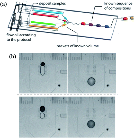 | ||
| Fig. 9 Droplet coalescence systems to obtain molecular gradients. (a) Simultaneously generation of individual droplets controlled by external electrovalves (reproduced from ref. 172 with permission from the Royal Society of Chemistry). (b) Pillars used to realize fusion without the demand for the synchronization, while the upper line and lower line show passive coalescence with different volume ratios, respectively (reproduced from ref. 174 with permission from Springer). | ||
One type is to trap a big sample droplet with multiple diluent droplets flowing in for sequential dilutions. Controlled by the local junction, the device presented by Niu et al.186 (shown in Fig. 10(a)) ensured the equal volume of the generated droplet and the inflow diluent droplet each time. The concentration of the trapped sample droplet decreased after each dilution as well as the concentration of the newly formed droplet, as shown in Fig. 10(b). By altering the relative volumes of the sample and diluent droplets or the initial concentrations of them, different concentration gradient profiles can be obtained.186 Indeed, more studies are focused on trapping arrays of sample droplets. A series of droplets with the same initial composition are stopped in the trap array and the long buffer plug is introduced to merge with them.187 After material exchanges, droplets with tuned contents are split and trapped again, during which the concentration of the sample droplet is decreased while that of the diluting plug is increased.188–190 As a result, the concentration variance of the diluting plug and trapped droplets gradually reduces along the flowing direction, as shown in Fig. 10(c).191–193 In practice, another kind of sample can be added into the buffer plug and thus droplet arrays of multi-component concentration gradients are obtained instead. As shown in Fig. 10(d), the droplet array is obtained by diluting droplets containing blue dye with a yellow dye plug. Along the flowing direction, concentrations of the blue dye within the resulting droplets increase while concentrations of the yellow dye reduce.191 Based on earlier works, Bhattacharjee et al.194 recently presented an electro-coalescence based scheme for fluids with surfactants, which could also realize on-demand dilution by alternatively switching the active control field. It is noteworthy that the size of the trap chamber should be designed properly as volumes of the resulting droplets are predetermined by the chamber capacity.195,196
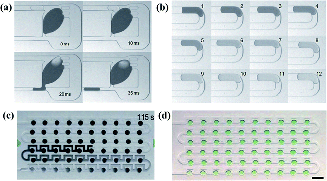 | ||
| Fig. 10 Dilution processes and the obtained droplet arrays with corresponding molecular gradients. (a) A complete process of the sequential dilution. (b) Images of sequential droplets taken from the same downstream position in (a) (reproduced from ref. 186 with permission from Nature Publishing Group). (c) The diluting process between a buffer plug and droplet arrays. (d) A generated droplet array with multi-component concentration gradients (reproduced from ref. 191 with permission from the Royal Society of Chemistry). | ||
Comparisons of typical characteristics of droplet-based platforms are shown in Table 2. Generally, the time span for droplet coalescence systems and droplet dilution systems are longer, which is caused by the time for droplet mixing. Take the system in Fig. 10(a) as an example, the generation time for a droplet is 35 ms while the mixing time is 500 ms when the total flow rate is 2 μL min−1. The increase of the flow rate is expected to promote the mixing speed as the mixing process depends on the shearing of the oil flow.186 Furthermore, the dynamic range of concentrations for droplet dilution systems is larger than the other two patterns, which can reach up to 5 orders of magnitude.191
3. Conclusions
Compared with traditional macroscale systems, concentration gradient generation methods based on microfluidic systems show various advantages and lots of applications are widely developed. In this paper, these microfluidic methods are classified by the presence or absence of shearing, as well as the typical structure, the leading mechanism, the theoretical calculation, and the working scope of each method are summarized. At first, tree-shape networks are proposed with their simple designs and robust outcomes. However, their footprints are usually large and the shearing is present. Modifications aimed at some disadvantages are put forward while other limits still exist. Local blocking junctions or chambers are added to decrease the shear stress but the footprints are still large. Porous membranes could avoid the shearing but the structures are relatively complex. The Y-shape junction is introduced to reduce the size of devices but the shearing still holds while the pressure balance system could obtain the chemical gradient relatively fast and the shearing is avoided from the gradient chamber at the premise of the balanced pressure among all the units. Lately, droplet-based microfluidic systems are applied to yield the gradient within droplet arrays. With the isolated chambers wrapped by the interface, reactions within the droplets are protected from the outside disturbances and they are particularly suitable for quantitative assays. According to the requirements of the shearing, the structure, and the generation speed of specific applications, different systems are chosen and modifications are made to combine the advantages of alternative methods. It is also required to devise simple structures to generate on-demand chemical gradients that need experimental protocols of simple steps and theoretical predicts of easy calculations for users even of little specific background knowledge.Acknowledgements
The authors do thank the support of No. 11572013 of the National Natural Science Foundation of China.References
- F. Azizi, et al., Chemical neurostimulation using pulse code modulation (PCM) microfluidic chips, J. Neurosci. Methods, 2010, 192(2), 193–198 CrossRef CAS PubMed
.
- T. M. Keenan and A. Folch, Biomolecular gradients in cell culture systems, Lab Chip, 2008, 8(1), 34–57 RSC
.
- D. Wlodkowic and J. M. Cooper, Microfabricated analytical systems for integrated cancer cytomics, Anal. Bioanal. Chem., 2010, 398(1), 193–209 CrossRef CAS PubMed
.
- S. Schmidt and P. Friedl, Interstitial cell migration: integrin-dependent and alternative adhesion mechanisms, Cell Tissue Res., 2010, 339(1), 83–92 CrossRef CAS PubMed
.
- F. Wang., The Signaling Mechanisms Underlying Cell Polarity and Chemotaxis, Cold Spring Harbor Perspectives in Biology, 2009, vol. 1, 4, pp. a002980–a002980 Search PubMed
.
- H.-C. Chiang, et al., Overexpression of chemokine ligand 7 is associated with the progression of canine transmissible venereal tumor, BMC Vet. Res., 2012, 8(1), 1–7 CrossRef PubMed
.
- K. Lee, et al., 2-Layer based microfluidic concentration generator by hybrid serial and volumetric dilutions, Biomed. Microdevices, 2010, 12(2), 297–309 CrossRef PubMed
.
- G. S. Jeong, et al., Sprouting angiogenesis under a chemical gradient regulated by interactions with an endothelial monolayer in a microfluidic platform, Anal. Chem., 2011, 83(22), 8454–8459 CrossRef CAS PubMed
.
- Y. S. Torisawa, et al., Microfluidic platform for chemotaxis in gradients formed by CXCL12 source-sink cells, Integr. Biol., 2010, 2(11–12), 680–686 RSC
.
- J. M. Lee, et al., An integrated microfluidic culture device to regulate endothelial cell differentiation from embryonic stem cells, Electrophoresis, 2011, 32(22), 3133–3137 CrossRef CAS PubMed
.
- W. Saadi, et al., A parallel-gradient microfluidic chamber for quantitative analysis of breast cancer cell chemotaxis, Biomed. Microdevices, 2006, 8(2), 109–118 CrossRef PubMed
.
- N. Li Jeon, et al., Neutrophil chemotaxis in linear and complex gradients of interleukin-8 formed in a microfabricated device, Nat. Biotechnol., 2002, 20(8), 826–830 CrossRef PubMed
.
- V. Vickerman, et al., Design, fabrication and implementation of a novel multi-parameter control microfluidic platform for three-dimensional cell culture and real-time imaging, Lab Chip, 2008, 8(9), 1468–1477 RSC
.
- J. Ruan, et al., Fabrication of a microfluidic chip containing dam, weirs and gradient generator for studying cellular response to chemical modulation, Mater. Sci. Eng., C, 2009, 29(3), 674–679 CrossRef CAS
.
- A. J. DeMello, Control and detection of chemical reactions in microfluidic systems, Nature, 2006, 442(7101), 394–402 CrossRef CAS PubMed
.
- H. Somaweera, A. Ibraguimov and D. Pappas, A review of chemical gradient systems for cell analysis, Anal. Chim. Acta, 2016, 907, 7–17 CrossRef CAS PubMed
.
- G. Zheng, Y. Wang and J. Qin, Microalgal motility measurement microfluidic chip for toxicity assessment of heavy metals, Anal. Bioanal. Chem., 2012, 404(10), 3061–3069 CrossRef CAS PubMed
.
- E. M. Miller and A. R. Wheeler, A Digital Microfluidic Approach to Homogeneous Enzyme Assays, Anal. Chem., 2008, 80(5), 1614–1619 CrossRef CAS PubMed
.
- H. Song and R. F. Ismagilov, Millisecond Kinetics on a Microfluidic Chip Using Nanoliters of Reagents, J. Am. Chem. Soc., 2003, 125(47), 14613–14619 CrossRef CAS PubMed
.
- F. Courtois, et al., An integrated device for monitoring time-dependent in vitro expression from single genes in picolitre droplets, Chembiochem, 2008, 9(3), 439–446 CrossRef CAS PubMed
.
- A. G. G. Toh, et al., Engineering microfluidic concentration gradient generators for biological applications, Microfluid. Nanofluid., 2014, 16(1–2), 1–18 CrossRef
.
- E. K. Sackmann, A. L. Fulton and D. J. Beebe, The present and future role of microfluidics in biomedical research, Nature, 2014, 507(7491), 181–189 CrossRef CAS PubMed
.
- J. Wu, et al., A simple and versatile microfluidic cell density gradient generator for quantum dot cytotoxicity assay, Lab Chip, 2013, 13(10), 1948–1954 RSC
.
- B. G. Chung, et al., Human neural stem cell growth and differentiation in a gradient-generating microfluidic device, Lab Chip, 2005, 5(4), 401–406 RSC
.
- L. F. Cai, et al., Droplet-based microfluidic flow injection system with large-scale concentration gradient by a single nanoliter-scale injection for enzyme inhibition assay, Anal. Chem., 2012, 84(1), 446–452 CrossRef CAS PubMed
.
- S. J. Wang, et al., Differential effects of EGF gradient profiles on MDA-MB-231 breast cancer cell chemotaxis, Exp. Cell Res., 2004, 300(1), 180–189 CrossRef CAS PubMed
.
- D. Irimia, D. A. Geba and M. Toner, Universal Microfluidic Gradient Generator, Anal. Chem., 2006, 78(10), 3472–3477 CrossRef CAS PubMed
.
- S. K. W. Dertinger, et al., Generation of Gradients Having Complex Shapes Using Microfluidic Networks, Anal. Chem., 2001, 73(6), 1240–1246 CrossRef CAS
.
- K. Campbell and A. Groisman, Generation of complex concentration profiles in microchannels in a logarithmically small number of steps, Lab Chip, 2007, 7(2), 264–272 RSC
.
- U. Haessler, et al., Dendritic cell chemotaxis in 3D under defined chemokine gradients reveals differential response to ligands CCL21 and CCL19, Proc. Natl. Acad. Sci. U. S. A., 2011, 108(14), 5614–5619 CrossRef CAS PubMed
.
- R. Dhumpa and M. G. Roper, Temporal gradients in microfluidic systems to probe cellular dynamics: a review, Anal. Chim. Acta, 2012, 743, 9–18 CrossRef CAS PubMed
.
- F. Wang, et al., Microfluidic delivery of small molecules into mammalian cells based on hydrodynamic focusing, Biotechnol. Bioeng., 2008, 100(1), 150–158 CrossRef CAS PubMed
.
- Y. Gao, P. Li and D. Pappas, A microfluidic localized, multiple cell culture array using vacuum actuated cell seeding: integrated anticancer drug testing, Biomed. Microdevices, 2013, 15(6), 907–915 CrossRef CAS PubMed
.
- Y. Nakashima and T. Yasuda, Cell differentiation guidance using chemical stimulation controlled by a microfluidic device, Sens. Actuators, A, 2007, 139(1–2), 252–258 CrossRef CAS
.
- Y. Liu, W. B. Butler and D. Pappas, Spatially selective reagent delivery into cancer cells using a two-layer microfluidic culture system, Anal. Chim. Acta, 2012, 743, 125–130 CrossRef CAS PubMed
.
- O. C. Amadi, et al., A low resistance microfluidic system for the creation of stable concentration gradients in a defined 3D microenvironment, Biomed. Microdevices, 2010, 12(6), 1027–1041 CrossRef CAS PubMed
.
- J. J. VanDersarl, A. M. Xu and N. A. Melosh, Rapid spatial and temporal controlled signal delivery over large cell culture areas, Lab Chip, 2011, 11(18), 3057–3063 RSC
.
- B. G. Chung, F. Lin and N. L. Jeon, A microfluidic multi-injector for gradient generation, Lab Chip, 2006, 6(6), 764–768 RSC
.
- X. Zhang and M. G. Roper, Microfluidic Perfusion System for Automated Delivery of Temporal Gradients to Islets of Langerhans, Anal. Chem., 2009, 81(3), 1162–1168 CrossRef CAS PubMed
.
- G. Khanal, et al., Ischemia/reperfusion injury of primary porcine cardiomyocytes in a low-shear microfluidic culture and analysis device, Analyst, 2011, 136(17), 3519–3526 RSC
.
- N. Ye, et al., Cell-based high content screening using an integrated microfluidic device, Lab Chip, 2007, 7(12), 1696–1704 RSC
.
- C. Kim, et al., A serial dilution microfluidic device using a ladder network generating logarithmic or linear concentrations, Lab Chip, 2008, 8(3), 473–479 RSC
.
- D. Irimia, et al., Microfluidic system for measuring neutrophil migratory responses to fast switches of chemical gradients, Lab Chip, 2006, 6(2), 191–198 RSC
.
- J. Pihl, et al., Microfluidic Gradient-Generating Device for Pharmacological Profiling, Anal. Chem., 2005, 77(13), 3897–3903 CrossRef CAS PubMed
.
- T. Frank and S. Tay, Flow-switching allows independently programmable, extremely stable, high-throughput diffusion-based gradients, Lab Chip, 2013, 13(7), 1273–1281 RSC
.
- J. Cao, et al., Uncovering toxicological complexity by multi-dimensional screenings in microsegmented flow: modulation of antibiotic interference by nanoparticles, Lab Chip, 2012, 12(3), 474–484 RSC
.
- E. Brouzes, et al., Droplet microfluidic technology for single-cell high-throughput screening, Proc. Natl. Acad. Sci. U. S. A., 2009, 106(34), 14195–14200 CrossRef CAS PubMed
.
- S. Ma, et al., On the flow topology inside droplets moving in rectangular microchannels, Lab Chip, 2014, 14(18), 3611 RSC
.
- S. Ma, et al., The microenvironment of double emulsions in rectangular microchannels, Lab Chip, 2015, 15(10), 2327–2334 RSC
.
- S. K. Dertinger, et al., Gradients of substrate-bound laminin orient axonal specification of neurons, Proc. Natl. Acad. Sci. U. S. A., 2002, 99(20), 12542–12547 CrossRef CAS PubMed
.
- K. Sun, Z. Wang and X. Jiang, Modular microfluidics for gradient generation, Lab Chip, 2008, 8(9), 1536–1543 RSC
.
- F. Lin, et al., Generation of dynamic temporal and spatial concentration gradients using microfluidic devices, Lab Chip, 2004, 4(3), 164–167 RSC
.
- K. W. Oh, et al., Design of pressure-driven microfluidic networks using electric circuit analogy, Lab Chip, 2012, 12(3), 515–545 RSC
.
- K. Lee, et al., Generalized serial dilution module for monotonic and arbitrary microfluidic gradient generators, Lab Chip, 2009, 9(5), 709–717 RSC
.
- H. A. Yusuf, et al., Optical imaging and analytical modelling of the dynamic concentration gradient of viscous inlet solutions in a microfabricated network design, Microelectron. Eng., 2009, 86(4–6), 1361–1364 CrossRef CAS
.
- H. A. Yusuf, et al., Systematic linearisation of a microfluidic gradient network with unequal solution inlet viscosities demonstrated using glycerol, Microfluid. Nanofluid., 2009, 8(5), 587–598 CrossRef
.
- N. Damean, et al., Simultaneous measurement of reactions in microdroplets filled by concentration gradients, Lab Chip, 2009, 9(12), 1707–1713 RSC
.
- A. D. Stroock, et al., Chaotic Mixer for Microchannels, Science, 2002, 295(5555), 647–651 CrossRef CAS PubMed
.
- X. Jiang, et al., A Miniaturized, Parallel, Serially Diluted Immunoassay for Analyzing Multiple Antigens, J. Am. Chem. Soc., 2003, 125(18), 5294–5295 CrossRef CAS PubMed
.
- A. Russom, D. Irimia and M. Toner, Chemical gradient-mediated melting curve analysis for genotyping of SNPs, Electrophoresis, 2009, 30(14), 2536–2543 CrossRef CAS PubMed
.
- D. L. Englert, M. D. Manson and A. Jayaraman, Flow-Based Microfluidic Device for Quantifying Bacterial Chemotaxis in Stable, Competing Gradients, Appl. Environ. Microbiol., 2009, 75(13), 4557–4564 CrossRef CAS PubMed
.
- Y. Wang, T. Mukherjee and Q. Lin, Systematic modeling of microfluidic concentration gradient generators, J. Micromech. Microeng., 2006, 16(10), 2128–2137 CrossRef
.
- C. Joanne Wang, et al., A microfluidics-based turning assay reveals complex growth cone responses to integrated gradients of substrate-bound ECM molecules and diffusible guidance cues, Lab Chip, 2008, 8(2), 227–237 RSC
.
- E. Kang, et al., Novel PDMS cylindrical channels that generate coaxial flow, and application to fabrication of microfibers and particles, Lab Chip, 2010, 10(14), 1856–1861 RSC
.
- R. M. Lorenz, et al., Simultaneous generation of multiple aqueous droplets in a microfluidic device, Anal. Chim. Acta, 2008, 630(2), 124–130 CrossRef CAS PubMed
.
- P. J. Hung, et al., Continuous perfusion microfluidic cell culture array for high-throughput cell-based assays, Biotechnol. Bioeng., 2005, 89(1), 1–8 CrossRef CAS PubMed
.
- P. J. Lee, et al., Nanoliter scale microbioreactor array for quantitative cell biology, Biotechnol. Bioeng., 2006, 94(1), 5–14 CrossRef CAS PubMed
.
- Y. Li, et al., High-throughput single cell multidrug resistance analysis with multifunctional gradients-customizing microfluidic device, Sens. Actuators, B, 2016, 225, 563–571 CrossRef CAS
.
- Y. B. Li, et al., Zebrafish on a Chip: A Novel Platform for Real-Time Monitoring of Drug-Induced Developmental Toxicity, PLoS One, 2014, 9(4), 8 Search PubMed
.
- F. Lin, et al., Neutrophil Migration in Opposing Chemoattractant Gradients Using Microfluidic Chemotaxis Devices, Ann. Biomed. Eng., 2005, 33(4), 475–482 CrossRef PubMed
.
- N. L. Jeon, et al., Generation of Solution and Surface Gradients Using Microfluidic Systems, Langmuir, 2000, 16(22), 8311–8316 CrossRef CAS
.
- D. L. Englert, M. D. Manson and A. Jayaraman, Investigation of bacterial chemotaxis in flow-based microfluidic devices, Nat. Protoc., 2010, 5(5), 864–872 CrossRef CAS PubMed
.
- G. Vozzi, et al., Finite element modelling and design of a concentration gradient generating
bioreactor: application to biological pattern formation and toxicology, Toxicol. In Vitro, 2010, 24(6), 1828–1837 CrossRef CAS PubMed
.
- G. M. Walker, et al., Effects of flow and diffusion on chemotaxis studies in a microfabricated gradient generator, Lab Chip, 2005, 5(6), 611–618 RSC
.
- B. R. Gorman and J. P. Wikswo, Characterization of transport in microfluidic gradient generators, Microfluid. Nanofluid., 2007, 4(4), 273–285 CrossRef
.
- X. Jiang, et al., A General Method for Patterning Gradients of Biomolecules on Surfaces Using Microfluidic Networks, Anal. Chem., 2005, 77(8), 2338–2347 CrossRef CAS PubMed
.
- G. M. Walker, H. C. Zeringue and D. J. Beebe, Microenvironment design considerations for cellular scale studies, Lab Chip, 2004, 4(2), 91–97 RSC
.
- K. Hattori, S. Sugiura and T. Kanamori, Generation of arbitrary monotonic concentration profiles by a serial dilution microfluidic network composed of microchannels with a high fluidic-resistance ratio, Lab Chip, 2009, 9(12), 1763–1772 RSC
.
- S. Sugiura, K. Hattori and T. Kanamori, Microfluidic Serial Dilution Cell-Based Assay for Analyzing Drug Dose Response over a Wide Concentration Range, Anal. Chem., 2010, 82(19), 8278–8282 CrossRef CAS PubMed
.
- C. Y. Chen, A. M. Wo and D. S. Jong, A microfluidic concentration generator for dose-response assays on ion channel pharmacology, Lab Chip, 2012, 12(4), 794–801 RSC
.
- B. Zhou, et al., Generation of tunable and pulsatile concentration gradients via microfluidic network, Microfluid. Nanofluid., 2015, 18(2), 175–184 CrossRef CAS
.
- H. Abdulla Yusuf, et al., Novel microsystems for concentration gradient generation through computer optimization with validation using optical instrumentation, Microelectron. Eng., 2008, 85(5–6), 1265–1268 CrossRef CAS
.
- H. Abdulla Yusuf, et al., Optimisation and analysis of microreactor designs for microfluidic gradient generation using a purpose built optical detection system for entire chip imaging, Lab Chip, 2009, 9(13), 1882–1889 RSC
.
- C. Neils, et al., Combinatorial mixing of microfluidic streams, Lab Chip, 2004, 4(4), 342–350 RSC
.
- E. Biddiss and D. Li, Electrokinetic generation of temporally and spatially stable concentration gradients in microchannels, J. Colloid Interface Sci., 2005, 288(2), 606–615 CrossRef CAS PubMed
.
- M. A. Holden, et al., Generating fixed concentration arrays in a microfluidic device, Sens. Actuators, B, 2003, 92(1–2), 199–207 CrossRef CAS
.
- H. Somaweera, A. Ibragimov and D. Pappas, Generation of a chemical gradient across an array of 256 cell cultures in a single chip, Analyst, 2013, 138(19), 5566–5571 RSC
.
- E. M. Lucchetta, et al., Dynamics of Drosophila embryonic patterning network perturbed in space and time using microfluidics, Nature, 2005, 434(7037), 1134–1138 CrossRef CAS PubMed
.
- M. Meier, E. M. Lucchetta and R. F. Ismagilov, Chemical stimulation of the Arabidopsis thaliana root using multi-laminar flow on a microfluidic chip, Lab Chip, 2010, 10(16), 2147–2153 RSC
.
- P. Rosa, et al., High-throughput study of alpha-synuclein expression in yeast using microfluidics for control of local cellular microenvironment, Biomicrofluidics, 2012, 6(1), 14109–141099 CrossRef PubMed
.
- Z. Tong, et al., Chemotaxis of Cell Populations through Confined Spaces at Single-Cell Resolution, PLoS One, 2012, 7(1), e29211 CAS
.
- H. Somaweera, et al., On-chip gradient generation in 256 microfluidic cell cultures: simulation and experimental validation, Analyst, 2015, 140(15), 5029–5038 RSC
.
- A. E. Kamholz and P. Yager, Molecular diffusive scaling laws in pressure-driven microfluidic channels: deviation from one-dimensional Einstein approximations, Sens. Actuators, B, 2002, 82(1), 117–121 CrossRef CAS
.
- R. F. Ismagilov, et al., Experimental and theoretical scaling laws for transverse diffusive broadening in two-phase laminar flows in microchannels, Appl. Phys. Lett., 2000, 76(17), 2376 CrossRef CAS
.
- A. E. Kamholz and P. Yager, Theoretical Analysis of Molecular Diffusion in Pressure-Driven Laminar Flow in Microfluidic Channels, Biophys. J., 2001, 80(1), 155–160 CrossRef CAS PubMed
.
- A. Hatch, et al., A rapid diffusion immunoassay in a T-sensor, Nat. Biotechnol., 2001, 19(5), 461–465 CrossRef CAS PubMed
.
- H. J. Koo, et al., Polymer brushes patterned with micrometer-scale chemical gradients using laminar co-flow, ACS Appl. Mater. Interfaces, 2014, 6(16), 14320–14326 CAS
.
- P. J. A. Kenis, R. F. Ismagilov and G. M. Whitesides, Microfabrication Inside Capillaries Using Multiphase Laminar Flow Patterning, Science, 1999, 285(5424), 83–85 CrossRef CAS PubMed
.
- J. Y. Park, et al., Gradient generation by an osmotic pump and the behavior of human mesenchymal stem cells under the fetal bovine serum concentration gradient, Lab Chip, 2007, 7(12), 1673–1680 RSC
.
- Y. Zhou, et al., Generation of complex concentration profiles by partial diffusive mixing in multi-stream laminar flow, Lab Chip, 2009, 9(10), 1439–1448 RSC
.
- T. I. Moore, et al., Robust Spatial Sensing of Mating Pheromone Gradients by Yeast Cells, PLoS One, 2008, 3(12), e3865 Search PubMed
.
- T. Long and R. M. Ford, Enhanced Transverse Migration of Bacteria by Chemotaxis in a Porous T-Sensor, Environ. Sci. Technol., 2009, 43(5), 1546–1552 CrossRef CAS PubMed
.
- J. S. H. Lee, Y. Hu and D. Li, Electrokinetic concentration gradient generation using a converging–diverging microchannel, Anal. Chim. Acta, 2005, 543(1–2), 99–108 CrossRef CAS
.
- B. H. Weigl and P. Yager, Microfluidic Diffusion-Based Separation and Detection, Science, 1999, 283(5400), 346–347 CrossRef
.
- C. Bathany, et al., High throughput assay of diffusion through Cx43 gap junction channels with a microfluidic chip, Anal. Chem., 2011, 83(3), 933–939 CrossRef CAS PubMed
.
- G. Walker, Cell infection within a microfluidic device using virus gradients, Sens. Actuators, B, 2004, 98(2–3), 347–355 CrossRef CAS
.
- S. Takayama, et al., Selective Chemical Treatment of Cellular Microdomains Using Multiple Laminar Streams, Chem. Biol., 2003, 10(2), 123–130 CrossRef CAS PubMed
.
- A. D. van der Meer, et al., A microfluidic wound-healing assay for quantifying endothelial cell migration, Am. J. Physiol.: Heart Circ. Physiol., 2010, 298(2), H719–H725 CrossRef CAS PubMed
.
- D. Irimia, et al., Polar stimulation and constrained cell migration in microfluidic channels, Lab Chip, 2007, 7(12), 1783–1790 RSC
.
- A. Shamloo, et al., Endothelial cell polarization and chemotaxis in a microfluidic device, Lab Chip, 2008, 8(8), 1292–1299 RSC
.
- C. R. Kothapalli, et al., A high-throughput microfluidic assay to study neurite response to growth factor gradients, Lab Chip, 2011, 11(3), 497–507 RSC
.
- J. Diao, et al., A three-channel microfluidic device for generating static linear gradients and its application to the quantitative analysis of bacterial chemotaxis, Lab Chip, 2006, 6(3), 381–388 RSC
.
- Y. A. Chen, et al., Generation of oxygen gradients in microfluidic devices for cell culture using spatially confined chemical reactions, Lab Chip, 2011, 11(21), 3626–3633 RSC
.
- N. Ye, C. Bathany and S. Z. Hua, Assay for molecular transport across gap junction channels in one-dimensional cell arrays, Lab Chip, 2011, 11(6), 1096–1101 RSC
.
- H. Wu, B. Huang and R. N. Zare, Generation of Complex, Static Solution Gradients in Microfluidic Channels, J. Am. Chem. Soc., 2006, 128(13), 4194–4195 CrossRef CAS PubMed
.
- V. V. Abhyankar, et al., Characterization of a membrane-based gradient generator for use in cell-signaling studies, Lab Chip, 2006, 6(3), 389–393 RSC
.
- H. Xu, M. M. Ferreira and S. C. Heilshorn, Small-molecule axon-polarization studies enabled by a shear-free microfluidic gradient generator, Lab Chip, 2014, 14(12), 2047–2056 RSC
.
- S. Y. Cheng, et al., A hydrogel-based microfluidic device for the studies of directed cell migration, Lab Chip, 2007, 7(6), 763–769 RSC
.
- V. V. Abhyankar, et al., A platform for assessing chemotactic migration within a spatiotemporally defined 3D microenvironment, Lab Chip, 2008, 8(9), 1507–1515 RSC
.
- U. Haessler, et al., An agarose-based microfluidic platform with a gradient buffer for 3D chemotaxis studies, Biomed. Microdevices, 2009, 11(4), 827–835 CrossRef CAS PubMed
.
- B. Mosadegh, et al., Generation of Stable Complex Gradients Across Two-Dimensional Surfaces and Three-Dimensional Gels, Langmuir, 2007, 23(22), 10910–10912 CrossRef CAS PubMed
.
- T. Ahmed, T. S. Shimizu and R. Stocker, Bacterial chemotaxis in linear and nonlinear steady microfluidic gradients, Nano Lett., 2010, 10(9), 3379–3385 CrossRef CAS PubMed
.
- M. Morel, et al., Concentration landscape generators for shear free dynamic chemical stimulation, Lab Chip, 2012, 12(7), 1340–1346 RSC
.
- C. C. Peng, et al., A microfluidic cell culture array with various oxygen tensions, Lab Chip, 2013, 13(16), 3239–3245 RSC
.
- C. W. Chang, et al., A polydimethylsiloxane–polycarbonate hybrid microfluidic device capable of generating perpendicular chemical and oxygen gradients for cell culture studies, Lab Chip, 2014, 14(19), 3762–3772 RSC
.
- Y. Zhou and Q. Lin, Microfluidic flow-free generation of chemical concentration gradients, Sens. Actuators, B, 2014, 190, 334–341 CrossRef CAS
.
- A. Abbott, Cell culture: Biology's new dimension, Nature, 2003, 424(6951), 870–872 CrossRef CAS PubMed
.
- W. Saadi, et al., Generation of stable concentration gradients in 2D and 3D environments using a microfluidic ladder chamber, Biomed. Microdevices, 2007, 9(5), 627–635 CrossRef PubMed
.
- S. Paliwal, et al., MAPK-mediated bimodal gene expression and adaptive gradient sensing in yeast, Nature, 2007, 446(7131), 46–51 CrossRef CAS PubMed
.
- K. Glover, J. Strang and A. Lubansky, Characterising the effect of geometry on a microchamber for producing controlled concentration gradients, Chem. Eng. Sci., 2014, 117, 389–395 CrossRef CAS
.
- J. Atencia, J. Morrow and L. E. Locascio, The microfluidic palette: a diffusive gradient generator with spatio-temporal control, Lab Chip, 2009, 9(18), 2707–2714 RSC
.
- M. E. Brett, et al., A microfluidic device that forms and redirects pheromone gradients to study chemotropism in yeast, Lab Chip, 2012, 12(17), 3127–3134 RSC
.
- E. Cimetta, et al., Microfluidic device generating stable concentration gradients for long term cell culture: application to Wnt3a regulation of beta-catenin signaling, Lab Chip, 2010, 10(23), 3277–3283 RSC
.
- J. Atencia, G. A. Cooksey and L. E. Locascio, A robust diffusion-based gradient generator for dynamic cell assays, Lab Chip, 2012, 12(2), 309–316 RSC
.
- S. Garcia, et al., Generation of stable orthogonal gradients of chemical concentration and substrate stiffness in a microfluidic device, Lab Chip, 2015, 15(12), 2606–2614 RSC
.
- T. Nisisako, T. Torii and T. Higuchi, Droplet formation in a microchannel network, Lab Chip, 2002, 2(1), 24–26 RSC
.
- K. Wang, et al., Microdroplet coalescences at microchannel junctions with different collision angles, AIChE J., 2013, 59(2), 643–649 CrossRef CAS
.
- H. Song, et al., On-Chip Titration of an Anticoagulant Argatroban and Determination of the Clotting Time within Whole Blood or Plasma Using a Plug-Based Microfluidic System, Anal. Chem., 2006, 78(14), 4839–4849 CrossRef CAS PubMed
.
- E. Um, M. E. Rogers and H. A. Stone, Combinatorial generation of droplets by controlled assembly and coalescence, Lab Chip, 2013, 13(23), 4674–4680 RSC
.
- W. Shi, et al., Droplet microfluidics for characterizing the neurotoxin-induced responses in individual Caenorhabditis elegans, Lab Chip, 2010, 10(21), 2855–2863 RSC
.
- J. Xu, et al., Droplet-based microfluidic device for multiple-droplet clustering, Lab Chip, 2012, 12(4), 725–730 RSC
.
- M. Sun, Z. S. Khan and S. A. Vanapalli, Blood plasma separation in a long two-phase plug flowing through disposable tubing, Lab Chip, 2012, 12(24), 5225–5230 RSC
.
- A. Huebner, et al., Static microdroplet arrays: a microfluidic device for droplet trapping, incubation and release for enzymatic and cell-based assays, Lab Chip, 2009, 9(5), 692–698 RSC
.
- C. N. Baroud, F. Gallaire and R. Dangla, Dynamics of microfluidic droplets, Lab Chip, 2010, 10(16), 2032–2045 RSC
.
- T. S. Kaminski, et al., Automated generation of libraries of nL droplets, Lab Chip, 2012, 12(20), 3995–4002 RSC
.
- S. L. Sjostrom, H. N. Joensson and H. A. Svahn, Multiplex analysis of enzyme kinetics and inhibition by droplet microfluidics using picoinjectors, Lab Chip, 2013, 13(9), 1754–1761 RSC
.
- E. Fradet, et al., Combining rails and anchors with laser forcing for selective manipulation within 2D droplet arrays, Lab Chip, 2011, 11(24), 4228 RSC
.
- C. J. Ochs and A. R. Abate, Rapid modulation of droplet composition with pincer microvalves, Lab Chip, 2015, 15(1), 52–56 RSC
.
- A. B. Theberge, G. Whyte and W. T. S. Huck, Generation of Picoliter Droplets with Defined Contents and Concentration Gradients from the Separation of Chemical Mixtures, Anal. Chem., 2010, 82(9), 3449–3453 CrossRef CAS PubMed
.
- B. Zheng, et al., A droplet-based, composite PDMS/glass capillary microfluidic system for evaluating protein crystallization conditions by microbatch and vapor-diffusion methods with on-chip X-ray diffraction, Angew. Chem., Int. Ed. Engl., 2004, 43(19), 2508–2511 CrossRef CAS PubMed
.
- P. Laval, et al., A microfluidic device based on droplet storage for screening solubility diagrams, Lab Chip, 2007, 7(7), 829–834 RSC
.
- S. Cho, et al., Droplet-based microfluidic platform for high-throughput, multi-parameter screening of photosensitizer activity, Anal. Chem., 2013, 85(18), 8866–8872 CrossRef CAS PubMed
.
- J. W. Choi, et al., High-throughput analysis of protein-protein interactions in picoliter-volume droplets using fluorescence polarization, Anal. Chem., 2012, 84(8), 3849–3854 CrossRef CAS PubMed
.
- Y. Wang and J. Wang, Mixed hydrogel bead-based tumor spheroid formation and anticancer drug testing, Analyst, 2014, 139(10), 2449–2458 RSC
.
- F. Gielen, et al., Interfacing microwells with nanoliter compartments: a sampler generating high-resolution concentration gradients for quantitative biochemical analyses in droplets, Anal. Chem., 2015, 87(1), 624–632 CrossRef CAS PubMed
.
- J.-W. Choi, et al., Integrated pneumatic micro-pumps for high-throughput droplet-based microfluidics, RSC Adv., 2014, 4(39), 20341–20345 RSC
.
- B. Kintses, et al., Picoliter cell lysate assays in microfluidic droplet compartments for directed enzyme evolution, Chem. Biol., 2012, 19(8), 1001–1009 CrossRef CAS PubMed
.
- H. H. Jeong, et al., A highly addressable static droplet array enabling digital control of a single droplet at pico-volume resolution, Lab Chip, 2016, 16(9), 1698–1707 RSC
.
- S. Zeng, et al., Microvalve-actuated precise control of individual droplets in microfluidic devices, Lab Chip, 2009, 9(10), 1340–1343 RSC
.
- O. J. Miller, et al., High-resolution dose–response screening using droplet-based microfluidics, Proc. Natl. Acad. Sci. U. S. A., 2012, 109(2), 378–383 CrossRef CAS PubMed
.
- R. Thakur, A. M. Amin and S. Wereley, On-chip dilution in nanoliter droplets, Analyst, 2015, 140(17), 5855–5859 RSC
.
- W.-B. Du, et al., Automated Microfluidic Screening Assay Platform Based on DropLab, Anal. Chem., 2010, 82(23), 9941–9947 CrossRef CAS PubMed
.
- J. Wegrzyn, et al., Microfluidic architectures for efficient generation of chemistry gradations in droplets, Microfluid. Nanofluid., 2012, 14(1–2), 235–245 Search PubMed
.
- C.-H. Yeh, Y.-C. Chen and Y.-C. Lin, Generation of droplets with different concentrations using gradient-microfluidic droplet generator, Microfluid. Nanofluid., 2011, 11(3), 245–253 CrossRef CAS
.
- R. Dangla, S. C. Kayi and C. N. Baroud, Droplet microfluidics driven by gradients of confinement, Proc. Natl. Acad. Sci. U. S. A., 2013, 110(3), 853–858 CrossRef CAS PubMed
.
- D. K. Kang, et al., 3D Droplet Microfluidic Systems for High-Throughput Biological Experimentation, Anal. Chem., 2015, 87(21), 10770–10778 CrossRef CAS PubMed
.
- M. P. Bui, et al., Enzyme kinetic measurements using a droplet-based microfluidic system with a concentration gradient, Anal. Chem., 2011, 83(5), 1603–1608 CrossRef CAS PubMed
.
- C. G. Yang, et al., A microfluidic concentration-gradient droplet array generator for the production of multi-color nanoparticles, Lab Chip, 2013, 13(14), 2815–2820 RSC
.
- V. van Steijn, et al., Block-and-break generation of microdroplets with fixed volume, Biomicrofluidics, 2013, 7(2), 24108 CrossRef PubMed
.
- S. Jambovane, et al., Creation of stepwise concentration gradient in picoliter droplets for parallel reactions of matrix metalloproteinase II and IX, Anal. Chem., 2011, 83(9), 3358–3364 CrossRef CAS PubMed
.
- K. Churski, P. Korczyk and P. Garstecki, High-throughput automated droplet microfluidic system for screening of reaction conditions, Lab Chip, 2010, 10(7), 816–818 RSC
.
- K. Churski, et al., Rapid screening of antibiotic toxicity in an automated microdroplet system, Lab Chip, 2012, 12(9), 1629–1637 RSC
.
- X. Niu, et al., Pillar-induced droplet merging in microfluidic circuits, Lab Chip, 2008, 8(11), 1837–1841 RSC
.
- H. Zhou and S. Yao, A facile on-demand droplet microfluidic system for lab-on-a-chip applications, Microfluid. Nanofluid., 2014, 16(4), 667–675 CrossRef CAS
.
- F. Guo, et al., Valve-based microfluidic device for droplet on-demand operation and static assay, Appl. Phys. Lett., 2010, 97(23), 233701 CrossRef
.
- J. Clausell-Tormos, A. D. Griffiths and C. A. Merten, An automated two-phase microfluidic system for kinetic analyses and the screening of compound libraries, Lab Chip, 2010, 10(10), 1302–1307 RSC
.
- Z. Liu, et al., Droplet coalescence at microchannel intersection chambers with different shapes, Soft Matter, 2016, 12(26), 5797–5807 RSC
.
- J. Shemesh, et al., Coalescence-assisted generation of single nanoliter droplets with predefined composition, Lab Chip, 2011, 11(19), 3225–3230 RSC
.
- X. Sun, et al., Controlled dispensing and mixing of pico- to nanoliter volumes using on-demand droplet-based microfluidics, Microfluid. Nanofluid., 2013, 15(1), 117–126 CrossRef CAS PubMed
.
- S. H. Jin, et al., A programmable microfluidic static droplet array for droplet generation, transportation, fusion, storage, and retrieval, Lab Chip, 2015, 15(18), 3677–3686 RSC
.
- X. Niu, et al., Electro-Coalescence of Digitally Controlled Droplets, Anal. Chem., 2009, 81(17), 7321–7325 CrossRef CAS PubMed
.
- S. Q. Gu, et al., Multifunctional picoliter droplet manipulation platform and its application in single cell analysis, Anal. Chem., 2011, 83(19), 7570–7576 CrossRef CAS PubMed
.
- F. Gielen, et al., A fully unsupervised compartment-on-demand platform for precise nanoliter assays of time-dependent steady-state enzyme kinetics and inhibition, Anal. Chem., 2013, 85(9), 4761–4769 CrossRef CAS PubMed
.
- X. Xiang, et al., Real-time luminescence-based colorimetric determination of double-strand DNA in droplet on demand, Biosens. Bioelectron., 2012, 32(1), 43–49 CrossRef CAS PubMed
.
- X. Xiang, et al., Stepwise reagent introduction-based droplet platform for multiplexed DNA sensing, Biosens. Bioelectron., 2013, 49, 403–409 CrossRef CAS PubMed
.
- X. Niu, et al., A microdroplet dilutor for high-throughput screening, Nat. Chem., 2011, 3(6), 437–442 CrossRef CAS PubMed
.
- H. H. Jeong, et al., Microfluidic static droplet array for analyzing microbial communication on a population gradient, Lab Chip, 2015, 15(3), 889–899 RSC
.
- M. Sun and S. A. Vanapalli, Generation of chemical concentration gradients in mobile droplet arrays via fragmentation of long immiscible diluting plugs, Anal. Chem., 2013, 85(4), 2044–2048 CrossRef CAS PubMed
.
- P. M. Korczyk, et al., Microfluidic traps for hard-wired operations on droplets, Lab Chip, 2013, 13(20), 4096–4102 RSC
.
- J. Shemesh, et al., Stationary nanoliter droplet array with a substrate of choice for single adherent/nonadherent cell incubation and analysis, Proc. Natl. Acad. Sci. U. S. A., 2014, 111(31), 11293–11298 CrossRef CAS PubMed
.
- M. Sun, S. S. Bithi and S. A. Vanapalli, Microfluidic static droplet arrays with tuneable gradients in material composition, Lab Chip, 2011, 11(23), 3949–3952 RSC
.
- X. Huang, et al., On-site formation of emulsions by controlled air plugs, Small, 2014, 10(4), 758–765 CrossRef CAS PubMed
.
- L. Derzsi, T. S. Kaminski and P. Garstecki, Antibiograms in five pipetting steps: precise dilution assays in sub-microliter volumes with a conventional pipette, Lab Chip, 2016, 16(5), 893–901 RSC
.
- B. Bhattacharjee and S. A. Vanapalli, Electrocoalescence based serial dilution of microfluidic droplets, Biomicrofluidics, 2014, 8(4), 044111 CrossRef PubMed
.
- S. S. Bithi, et al., Coalescing drops in microfluidic parking networks: A multifunctional platform for drop-based microfluidics, Biomicrofluidics, 2014, 8(3), 034118 Search PubMed
.
- H. Wen, et al., A droplet microchip with substance exchange capability for the developmental study of C. elegans, Lab Chip, 2015, 15(8), 1905–1911 RSC
.
| This journal is © The Royal Society of Chemistry 2017 |

