Recent advances in the electrolytes for interfacial stability of high-voltage cathodes in lithium-ion batteries
Nam-Soon Choi
*a,
Jung-Gu Han
a,
Se-Young Ha
a,
Inbok Park
a and
Chang-Keun Back
b
aSchool of Energy and Chemical Engineering, Ulsan National Institute of Science and Technology (UNIST), 50 UNIST Way, Ulsan, 689-798, South Korea. E-mail: nschoi@unist.ac.kr
bCentral R&D Center, Hanwha Chemical Co. Ltd., Daejeoun City, 305-350, South Korea
First published on 3rd December 2014
Abstract
Advanced electrolytes with unique functions such as in situ formation of a stable artificial solid electrolyte interphase (SEI) layer on the anode and the cathode, and the improvement in oxidation stability of the electrolyte have recently gained recognition as a promising means for highly reliable lithium-ion batteries with high energy density. In this review, we describe several challenges for the cathode (spinel lithium manganese oxide (LMO), lithium cobalt oxide (LCO), lithium nickel cobalt manganese oxide (NCM), spinel lithium manganese nickel oxide (LNMO), and lithium-rich layered oxide (Li-rich cathode))-electrolyte interfaces and highlight the recent progress in the use of oxidative additives and high-voltage solvents in high-performance cells.
A Introduction
Li-ion batteries (LIBs) commercialized for portable electronic devices are the most feasible candidates for transportation applications (hybrid electric vehicles (HEVs), plug-in hybrid electric vehicles (PHEVs), and electric vehicles (EVs)), bulk electricity storage at power stations and load leveling of renewable energy sources (solar energy and wind power).1–3 The electrode reactions in LIBs are based on electrochemical reactions in which Li+ ions are intercalated or deintercalated from an open host structure with a concomitant addition or removal of electrons. Conventional carbonate solvents such as ethylene carbonate (EC) have been widely used as solvents because of their high dissociation ability, reasonably high ionic conductivity, and ability to form a proper SEI layer on the carbonaceous anode. However, conventional carbonate-solvent-based electrolytes exhibit inferior anodic stability of lower than 4.3 V vs. Li/Li+, which makes them highly unstable against high-voltage cathodes. Considering the potentials at which the anode materials react with Li ions, the electrolyte components (carbonates and salts) will be electrochemically reduced on the anodes, thereby resulting in the formation of a resistive surface film. The formation of surface films through the use of reducible and oxidizable additives in the electrolytes is considered to be one of the most effective strategies for stabilizing the electrode–electrolyte interface.Most studies on stabilizing the electrode–electrolyte interface have focused on anode solid electrolyte interphase (SEI) formers, such as vinylene carbonate (VC) and fluoroethylene carbonate (FEC).2,4–7 The formation of protective films on the anodes through the use of reducible additives could attain a noticeable improvement in the electrochemical properties of anodes coupled with LiCoO2 cathodes upon repeated cycling.8 Therefore, understanding the interfacial phenomena and controlling the interface between the electrode and the electrolyte is of considerable importance for rationally designing electrolytes for high-performance LIBs. As previously mentioned, the use of suitable electrolyte additives has been widely regarded as an efficient means of improving the electrochemical performance of LIBs.
Various cathode materials that operate at high voltages have recently gained attention as promising candidates for improving the energy density of lithium-ion cells.9–16
The practical application of high-voltage cathodes, such as lithium-rich cathode materials represented by the chemical compositions of xLi2MnO3·(1 − x)LiMO2 (M = Ni, Mn, Co) and LiNi0.5Mn1.5O4, in LIBs remains a formidable challenge because high-voltage cathodes suffer from the oxidative decomposition of LiPF6/carbonate-based electrolytes above 4.3 V vs. Li/Li+, which results in degradation of the electrodes and rapid capacity loss of cells.17–20
Several approaches have been explored to develop appropriate electrolyte systems for high-voltage cathodes in LIBs. To mitigate the undesirable oxidative decomposition of electrolytes at high voltages of greater than 4.3 V vs. Li/Li+, sulfone-based solvents,21,22 ionic liquids,23 and dinitrile solvents24 with high anodic stabilities have been investigated for use as high-voltage electrolytes. Unfortunately, these solvents suffer from high intrinsic viscosities and severe reductive decomposition on carbonaceous anode materials. Very recently, the Zhang group proposed an effective approach to overcome these problems.18 They demonstrated that the use of fluorinated carbonates as solvents could improve the inferior anodic stability of conventional electrolytes at high voltages and substantially enhance the cycling stability of LiNi0.5Mn1.5O4/Li4Ti5O12 electrochemical couples at 55 °C. In addition to developing solvents with high anodic stability, researchers have also investigated the use of functional oxidative additives to modify the surface chemistry of the cathode and attain high-performance cathodes for use in LIBs.25–27
In this review, we present the problematic issues regarding the interface between the high-voltage cathode and the electrolyte. We also highlight recent advancements in the development of advanced electrolytes, including sacrificial additives and solvents, to ensure high-performance cathodes in LIBs.
B Finding functional electrolyte additives
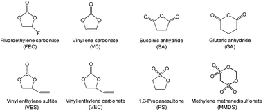
The development of electrolyte additives has concentrated on the formation of a robust and stable artificial solid-electrolyte interphase (SEI) on the anode. Because protection by the SEI against unwanted anode–electrolyte reactions affects the electrochemical properties of the anodes, the nature of the SEI on the anode is critically important. To properly design anode SEI formers, their first lowest unoccupied molecular orbital (LUMO) energy reflecting the reduction tendency is generally compared with that of ethylene carbonate (EC) as a conventional solvent. The most frequently used reducible additives in Li-ion cells with graphite and silicon anodes are vinylene carbonate (VC) and fluoroethylene carbonate (FEC).4,28 VC and FEC additives (Fig. 1) are very effective in stabilizing the anode–electrolyte interface, although their application for high-voltage cathodes is questionable. Moreover, because a tradeoff exists for the additive in forming an inadequate SEI for high-power applications, the additive content should be optimized to ensure that Li-ion cells possess good electrochemical performance.The primary process for discovering adequate oxidative additives is to calculate the highest occupied molecular orbital (HOMO) of compounds using a molecular orbital package-specifically, MOPAC, which is a popular computer program designed to implement semi-empirical quantum chemistry algorithms.
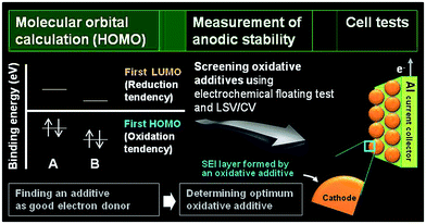
The electrochemical oxidation tendency is theoretically predicted through the HOMO energy of molecules without experiments. The first HOMO energy in Fig. 2 reflects the oxidation tendency because it is the orbital that readily loses an electron. On the basis of this concept, we can determine the proper oxidative additives acting as an electron donor by comparing the HOMO energy of various compounds. A comparison of the HOMO energies for compound A and B is presented in Fig. 2. Because the HOMO energy of compound A is higher than that of compound B, compound A can be utilized as an oxidative additive to form the SEI layer on the cathode surface. Notably, if the decomposition rate is not as high as the oxidation rate prior to decomposition of the conventional electrolyte, the SEI layer will hardly form on the cathode. Moreover, the oxidation behaviors of isolated additives may be different with their oxidations in a presence of anions and carbonate solvent molecules. The proper screening of appropriate oxidative additives requires additional experiments before the additives can be successfully used in Li-ion cells. Electrochemical floating tests at a constant charging voltage at a given typical time measure the leakage current of cells with a platinum electrode or a given cathode as the working electrode. This method enables an assessment of the anodic stability of the electrolyte at high voltages. The Zhang group compared the anodic stability of various fluorinated solvent-based electrolytes using this electrochemical floating test.18 In addition, linear sweep voltammetry (LSV) and cyclic voltammetry (CV) measurements define the anodic limit of electrolytes on a given working electrode by monitoring the anodic currents at high voltages. With these methods, promising additive candidates that may form a protective surface film on the cathode can be screened for use in high-voltage cathodes. Lastly, the most promising additive can be identified through evaluation of the electrochemical performances of cells constructed with the screened additives. High-voltage solvents with low HOMO energies compared to carbonate solvents such as EC can be also screened by the fundamental processes depicted in Fig. 2. Unlike the oxidative additives, a large amount of high-voltage solvents should be introduced to improve the anodic stability of the electrolyte. Therefore, the use of high-voltage solvents as a main solvent may reduce the dissociation degree of lithium salt and increase the viscosity of the electrolyte. Accordingly, the ionic conductivities of the electrolytes based on high-voltage solvents will decrease. To minimize the detrimental effect of high-voltage solvents on the bulk properties of the electrolyte and achieve the electrolyte with superior anodic stability, the electrolyte composition should be precisely controlled.
C Interfacial properties of LiMn2O4
1. Surface chemistry of LiMn2O4
Lithium manganese oxide (LiMn2O4) (LMO) with the spinel structure has been extensively investigated as a replacement for lithium cobalt oxide (LiCoO2) as a cathode material for high-energy and high-power batteries to replace lithium cobalt oxide (LiCoO2) due to its natural abundance, environmental benignity, and good safety characteristics.2,29,30 It is known that the main challenge in implementing the LMO cathode is the severe dissolution of manganese (Mn) in acidic electrolytes, particularly at elevated temperatures.31–36 The capacity fading of batteries based on the spinel structure cannot solely be explained by the loss of cathode active materials. The dissolved manganese ions move to the anode and thus lead to the self-discharge of lithiated graphite.33,37 Li-ion cells that contain LMO as the cathode and graphite as the anode generally experience severe capacity fading at elevated temperatures due to the migration of Mn out of the cathode toward the anode.37 Thus, even very small amounts of manganese ions in the electrolyte can affect the service life of lithium-ion batteries for large-scale power sources, such as EVs, HEVs, PHEVs, and smart grids based on renewable energies. Our group proposed a reasonable mechanism for the dissolution of manganese out of a delithiated LMO cathode. The dissolution of manganese induced by HF has been determined to be the main failure mechanism for the LMO cathode at elevated temperatures.34 Note that the majority of works focused on HF as the mediator for the dissolution of manganese from the LMO cathode in a lithiated (discharged) state.35,38 A possible mechanism for the change in oxidation state of manganese ions in a delithiated lithium manganese oxide cathode is shown in Fig. 3.39 In the fully delithiated LMO cathode, tetravalent manganese ions (Mn4+) are formed, as illustrated in Fig. 3. Reduction of Mn4+ to Mn3+ can occur through the acceptance of electrons produced by the oxidative decomposition of the LiPF6-based electrolyte. The resulting Mn3+ ions undergo a disproportionation reaction (2Mn3+ (solid) → Mn4+ (solid) + Mn2+ (solution)) on the surface of the LMO cathode particles, and Mn2+ ions, which are readily dissolved in the electrolyte, are formed. The dissolved Mn2+ ions lead to a considerable fading in the capacity of a full cell because depositing one Mn2+ ion causes two Li+ ions to be extracted from the lithiated graphite into the cell.33 Therefore, to obtain highly reliable Li-ion batteries that contain a spinel LMO cathode, the dissolution of Mn should be minimized.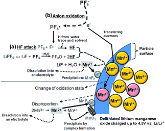 | ||
| Fig. 3 Schematic presentation for the manganese dissolution out of a delithiated LMO cathode (a) by the HF attack, (b) by the PF6− anion oxidation. Reproduced with permission.36 | ||
In addition to doping with an element that has a lower valence state, such as Al,40,41 and the formation of a surface coating,42–44 functional electrolyte additives that can form a robust protective film on the cathode and the anode are very effective in alleviating the detrimental impact of Mn ions migrating from the cathode to the anode.45–49 It is well known that VC as a highly effective reducible additive forms polymer-like species on the graphite anode and alleviates further irreversible side reactions of the electrolyte on the anode upon prolonged cycling.6 Some reports have indicated that VC may affect the surface chemistry of the cathode.50–52
Aurbach et al. reported that the VC additive is reactive toward both the graphite anode and the LMO cathode.4 As clearly shown in Fig. 4, the LMO cathode cycled in the VC-containing electrolyte exhibits peaks at approximately 2941 cm−1 (C–H stretching) and 1800 cm−1 (polycarbonate species stretching) unlike that cycled in a VC-free electrolyte, as shown in Fig. 4(a). This spectral feature indicates that the VC additive modifies the surface chemistry of the LMO cathode. Dedryvère et al. confirmed that polymer species are formed from the decomposed VC depositing on the graphite anode and LiCoO2 (LCO) cathode surfaces using ex situ XPS measurements.53 They proposed a possible mechanism for the formation of polymer species as a result of VC decomposition, as illustrated in Fig. 4(b). As clearly shown in the O 1s XPS spectra in Fig. 4(c), two new pronounced peaks at 533.5 and 534.5 eV, which were not observed in the spectrum of the VC-free electrolyte, appeared when the VC additive was added to the electrolyte. They reported that these peaks may be oxygenated organic species that originated from the decomposition of VC or products from the co-decomposition of VC and carbonate solvents.53,54
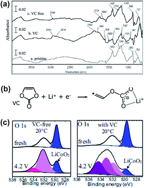 | ||
| Fig. 4 (a) FTIR spectra obtained from the LMO cathodes before and after being cycled in the VC-free and VC-added electrolytes. (b) Possible mechanism of the VC decomposition. The polymerization of VC may occur by the radical species. (c) O 1s XPS spectra of the LCO cathodes before and after being cycled in the VC-free and VC-added electrolytes. Reproduced with permission.4,53 | ||
2. Oxidative additives for LiMn2O4
Li et al. examined the effect of tris(trimethylsilyl) borate (TMSB) on the cycling property of the LMO cathode for Li-ion batteries.55 The Li/LMO half cells with 0.5 wt% TMSB additive exhibited only a 5% capacity loss after 180th cycles, whereas the cell with the reference electrolyte exhibited a 23% capacity loss at a rate of 1 C. To understand the improved electrochemical performance of the LMO cathode with the TMSB additive, they compared the surface chemistries of the LMO cathodes with and without the TMSB additive after 80 cycles. The C 1s XPS results revealed that the intensities of the peaks corresponding to the C–H and C![[double bond, length as m-dash]](https://www.rsc.org/images/entities/char_e001.gif) O groups on the surface of the LMO cathode cycled in the TMSB-containing electrolyte are considerably stronger than those of the cathode cycled with the reference electrolyte.55 In addition, it was found that the surface film on the LMO cathode cycled in the TMSB-containing electrolyte contains relatively less Li2CO3 compared with that cycled in the reference electrolyte. Very recently, methylene methanedisulfonate (MMDS) (Fig. 2) was investigated as an oxidative additive to improve the cycling performance of the LMO cathode charged up to 4.4 V at 60 °C.56 The LMO/graphite full cell with 0.5% MMDS additive exhibited superior capacity retention of 79.2% after 100 cycles at 60 °C compared to the reference electrolyte (Fig. 5(a)). As shown in the F 1s XPS spectra in Fig. 5(b), there is a clear disparity for both cathodes cycled at 60 °C. Unlike the additive-free electrolyte that exhibited the LiF peak at 685.0 eV, the LMO cathode cycled in the MMDS-containing electrolyte did not exhibit the LiF peak (Fig. 5(b)). In addition, the surface film covering the LMO cathode cycled in the additive-free electrolyte appears loose, as shown in Fig. 5(c). This less compact surface film cannot prevent the dissolution of Mn out of the LMO cathode during cycling at 60 °C.
O groups on the surface of the LMO cathode cycled in the TMSB-containing electrolyte are considerably stronger than those of the cathode cycled with the reference electrolyte.55 In addition, it was found that the surface film on the LMO cathode cycled in the TMSB-containing electrolyte contains relatively less Li2CO3 compared with that cycled in the reference electrolyte. Very recently, methylene methanedisulfonate (MMDS) (Fig. 2) was investigated as an oxidative additive to improve the cycling performance of the LMO cathode charged up to 4.4 V at 60 °C.56 The LMO/graphite full cell with 0.5% MMDS additive exhibited superior capacity retention of 79.2% after 100 cycles at 60 °C compared to the reference electrolyte (Fig. 5(a)). As shown in the F 1s XPS spectra in Fig. 5(b), there is a clear disparity for both cathodes cycled at 60 °C. Unlike the additive-free electrolyte that exhibited the LiF peak at 685.0 eV, the LMO cathode cycled in the MMDS-containing electrolyte did not exhibit the LiF peak (Fig. 5(b)). In addition, the surface film covering the LMO cathode cycled in the additive-free electrolyte appears loose, as shown in Fig. 5(c). This less compact surface film cannot prevent the dissolution of Mn out of the LMO cathode during cycling at 60 °C.
 | ||
| Fig. 5 (a) Discharge capacity retention of LMO/graphite full cell at 60 °C. (b) F 1s XPS spectra of LMO cathoes after 100 cycles at 60 °C. TEM images of LMO cathode surface cycled in (c) the additive-free electrolyte, (d) the MMDS-added electrolyte. Reproduced with permission.56 | ||
On the other hand, the MMDS additive produced a relatively compact and uniform SEI layer on the surface of the LMO cathode (Fig. 5(d)). A more compact SEI is expected to prevent the dissolution of Mn and to mitigate the decomposition of the electrolyte at the LMO cathode. Notably, the MMDS additive did not result in an improvement in the cycling stability of the LCO/graphite full cell charged up to 4.2 V vs. Li/Li+, whereas the LCO/graphite full cell charged up to 4.5 V in the MMDS-containing electrolyte exhibited a significantly improved discharge capacity retention. This result indicates that the MMDS additive acted as an SEI former that protected the surface of the LCO cathode when the cathode was charged to 4.5 V.26
D Functional additives for LiCoO2 and lithium nickel cobalt manganese oxide (NCM)
The Abe group noted that conventional electrolytes do not form a stable surface film on LiCoO2 (LCO) cathodes with a high charge cut-off voltage of 4.3 V; thus, the reversible capacity of a full cell coupled with the graphite anode is not increased.26 From this point of view, biphenyl (BP) (inset of Fig. 6), which is known to act as overcharging protection agent, has been proposed as an oxidative additive for building up a thin protective film on LCO cathodes. Abe et al. showed that HOMO energy of BP (−8.92 eV) is much higher than that of EC (−11.8 eV). Electrochemical cycling tests of type-18650 cylindrical cells at 45 °C confirmed that the addition of 0.1% BP provided better capacity retention of cells compared to the addition of 2% BP, as clearly shown in Fig. 6.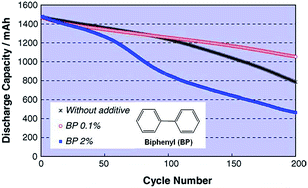 | ||
| Fig. 6 Cycle life of LiCoO2/graphite cylindrical cells with and without BP additive cycled between 2.7 V and 4.3 V at 45 °C. Reproduced with permission.26 | ||
Auger electron spectroscopy measurements of the surface film thickness on the LCO cathode revealed that the inferior cycling performance of the full cell with 2% BP additive was due to the formation of a thick SEI layer (217 Å after 200 cycles) that impeded the lithiation and delithiation kinetics of the LCO cathode.26 In contrast, a thin SEI layer (68 Å) was formed on the cathode in the cell with 0.1% BP.
The beneficial effect of tris(trimethylsilyl)borate (TMSB) additive (Fig. 7) on the electrochemical performance of LiNi0.5Co0.2Mn0.3O2/graphite full cells was clearly demonstrated in a high operating voltage range of 3.0–4.4 V (Fig. 8(b)) compared to the effect observed in the normal operating voltage range of 3.0–4.2 V (Fig. 8(a)).57 This result indicates that drastically improved cycling performance resulted from the formation of thin and stable TMSB-derived SEI layers on the cathode and from the coordination of PF6− and F− with the electron-deficient boron atom of TMSB.
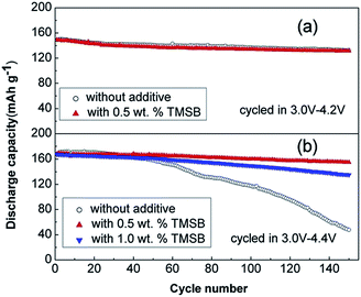 | ||
| Fig. 8 Cycling performance of LiNi0.5Co0.2Mn0.3O2/graphite cells cycled at a rate of 1 C in the voltage ranges of (a) 3.0–4.2 V and (b) 3.0–4.4 V. Reproduced with permission.57 | ||
Notably, the Lewis acid–base interaction between the electron-deficient boron atom of TMSB and F− may reduce the interfacial impedance of the cathode because the highly resistive LiF component can be dissolved from the SEI layer on the cathode. Indeed, the TMSB additive, which can dissolve the LiF from the SEI layer on the cathode and improve the poor thermal stability of LiPF6 salt via the coordination between the TMSB and PF6− anions, reduced the interfacial impedance of cycled Li/LFP half-cells and enhanced their cycling performance at 55 °C.58 Similarly, the Chang group reported that tris(pentafluorophenyl) borane (TPFPB), which also contains an electron-deficient boron atom, dissolved the LiF from the SEI layer on an LFP cathode and thereby led to decreased interfacial resistance of Li/LFP half-cells at elevated temperatures.59
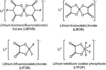
Interestingly, lithium tetrafluoro oxalato phosphate (LTFOP) (Fig. 9) as a salt-type additive could modify the surface film on the Li1.1[Ni1/3Co1/3Mn1/3]0.9O2 (NCM) cathode when the graphite/NCM full cell was charged to a low voltage of 4.0 V vs. Li/Li+.60 Although the LTFOP additive slightly improved the discharge capacity retention of the NCM cathode at 55 °C, it is clear that LTFOP tends to polymerize and form an SEI on the NCM cathode.
E Interfacial properties of LiNi0.5Mn1.5O4
1. Surface chemistry of LiNi0.5Mn1.5O4
It is widely accepted that HF and PF5 are formed in lithium-ion batteries with PC/LiPF6 electrolytes as a result of overheating and due to water impurities.61–63 Using density functional theory, Xing et al. determined that the oxidation of the propylene carbonate (PC) solvent leads to ring distortion,64 whereas the oxidation of the PC–PF6− complex results in the de-protonation of PC and the formation of HF and PF5 without the presence of water.59 They proposed that these chemical reactions occurred during the removal of an electron for the PC–PF6− complex before the ring-opening reaction of PC.64 In their density functional theory study, the oxidative decomposition pathways of the PC–PF6− complex were clearly observed, and the presence of the PF6− anion decreased the anodic stability of PC solvent and altered the decomposition kinetics.65 The reduction in the anodic stability of the electrolyte resulting from the presence of salt and the metal dissolution from the cathode resulting from acidic species such as HF should be addressed to enable the use of high-voltage cathodes in LIBs. LiNi0.5Mn1.5O4 (LNMO), which operates in the vicinity of 4.7 V vs. Li/Li+, has been investigated as a promising cathode material for high energy density Li-ion batteries.Aurbach et al. performed high-temperature storage tests of LNMO cathodes without carbon black and a PVDF binder to understand the surface chemistry of aged cathode materials at 60 °C.66 It was found that LiF, C–F, and PFx species were present on the aged LNMO cathode. The XPS measurements revealed that the Mn2+ and Ni2+ ions dissolved from the LNMO cathode are reduced on the lithium counter electrode in Li/LiNi0.5Mn1.5O4 cells cycled at elevated temperatures.67 In addition, they showed that the transformation of the active material to λ-MnO2 (2LiNi0.5Mn1.5O4 + 8H+ (from HF) → 2λ-MnO2 + Mn2+ + Ni2+ + 4Li+ + 4H2O + 2Ni0.5Mn1.5O4) occurs when stored at elevated temperatures in LiPF6-based electrolyte through ex situ Raman spectra. For the LNMO cathode aged at 60 °C for 45 days, the peak corresponding to λ-MnO2 appeared at 575 cm−1 (Fig. 10). This behavior was not uniform but rather localized in some parts of the active particles.
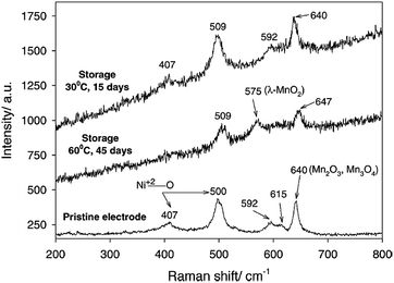 | ||
| Fig. 10 Ex situ Raman spectra obtained from the pristine LiNi0.5Mn1.5O4, the electrode stored at 30 °C for 15 days, and the electrode stored at 60 °C for 45 days in EC/DMC (1/2)/1.5 M LiPF6. Reproduced with permission.69 | ||
Lucht et al. investigated the electrochemical oxidation of LiPF6-based electrolytes as the LNMO cathodes were charged to various charge potentials. The XPS and FT-IR results revealed that EC readily oxides on the surface of delithiated LNMO cathodes at high charge potentials of greater than 4.3 V to form polyethylene carbonate.17 They proposed a possible mechanism for the decomposition of EC catalyzed by PF5 (Fig. 11(b)). The EC solvent may also undergo oxidative decomposition, resulting in a radical cation (EC˙+) at the high-voltage cathode, as illustrated in Fig. 11(a).68
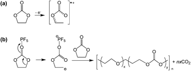 | ||
| Fig. 11 Possible mechanism for the EC decomposition via strong Lewis acid, PF5. Reproduced with permission.68 | ||
The surface chemistry of LNMO cathodes cycled in the LiPF6-based electrolyte were examined by ex situ XPS measurements (Fig. 12).13 The O 1s XPS spectra obtained from the LNMO cathodes before cycling show three types of oxygen (Fig. 12(b)): ether linkage (–C–O–C; 532–533 eV), carbonate (O–CO2–; 531.5 eV), and the oxygen in LNMO (529.5 eV). The peak attributed to the oxygen in LNMO sintered at 500 °C and 800 °C is considerably less intense for the cathodes cycled in EC/DEC/1 M LiPF6 for 100 cycles. This result indicates that the surface of the LNMO cathode materials is covered by the SEI layer (Fig. 12(c)). The F 1s spectra reveal the presence of PVDF binder on the cathode after 1 cycle. However, the LNMO cathode sintered at 500 °C, which exhibits high capacity fading after 100 cycles, and the one sintered at 800 °C exhibit two F 1s peaks: the first one at 684.3 eV is attributed to LiF and the second one at 685.6 eV corresponds to LixPFy/LixPOFz, which is produced by decomposition of the LiPF6 salt. Importantly, for the LNMO cathode sintered at 500 °C, the peak assigned to a resistive LiF was relatively intense compared to that for the cathode sintered at 800 °C, as presented in Fig. 12(d) and (e). Note that the migration of Li ions through LiF-based surface films is difficult.52 Based on the XPS results, they determined that the surface films on the cycled LNMO cathodes are composed of polymer species with ether and carbonate moieties formed by decomposition of the solvent, LiF, and LixPOFz/LixPFy resulting from decomposition of the salt.
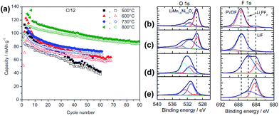 | ||
| Fig. 12 (a) Charge (filled symbols) and discharge (blank symbols) capacities of LNMO sintered at various temperatures. O 1s, F 1s, and P 2p XPS spectra of LNMO cathode sintered at 800 °C (b) before cycling, (c) after 1 cycle, (d) after 100 cycles, (e) LNMO cathode sintered at 500 °C after 100 cycles. Reproduced with permission.13 | ||
It is believed that the characteristics of the surface layer formed on the LNMO cathode represent a key parameter that affect the kinetics of electrochemical reactions and the interfacial stability of the cathode. To avoid the undesirable decomposition of the electrolyte components at high voltages, various promising additives for the in situ formation of a thin and robust artificial SEI layer on the LNMO cathode have been explored. Recently, the Kim group reported that the oxidative decomposition of the electrolyte at high voltages primarily occurs on the surface of not LiNi0.5Mn1.5O4 (LNMO) cathode materials but rather on the electrical conducting agent, carbon black particles.69 They also reported that polyethylene carbonate-like polymeric species produced by the decomposition of EC and inorganic fluoride (LiF, MnF2 and others) and phosphate species can deposit on the surface of LNMO particles. We previously reported that the conventional electrolyte electrochemically oxidizes at the LiNi0.5Mn1.5O4 cathode charged to 5.0 V and the color in the separator becomes yellowish brown when the charge cut-off potential is increased to 5.0 V in the conventional electrolyte; at this point, the baseline electrolyte solution turned light brown. This is because the baseline electrolyte underwent significant oxidation above 4.6 V, and consequently, colored compounds between the separator and the cathode were formed.70
2. High-voltage solvents for LiNi0.5Mn1.5O4
Zhang et al. proposed the use of fluorinated carbonates as the promising high-voltage solvents, which is expected to greatly improve the anodic stability of the electrolytes, as shown in Fig. 9(a).18 It is known that the presence of transition metals in the cathode might catalyze the oxidative decomposition of the electrolyte and that the evolving current might not be detectable due to an overlap with the anodic peaks for the electrochemical oxidation of cathode materials.71,72 To evaluate the anodic stability of the electrolyte, a method for measuring the leakage current at a constant voltage was employed. They reported that the current intensity reflects the electrochemical decomposition of the electrolyte at a given voltage and the anodic potential limit of the electrolyte, as indicated by a sudden increase in the leakage current. It was clearly shown that the electrolytes with the non-fluorinated linear carbonate EMC exhibited relatively high leakage currents at a high voltage of 5.7 V compared to the electrolytes with fluorinated-EMC (F-EMC). Importantly, unlike the linear carbonate, the non-fluorinated cyclic carbonate, EC-containing electrolytes produced a minimal leakage current at 5.7 V, as shown in Fig. 13(b).18 A detailed comparison revealed that the replacement of EC by F-AEC (E5 electrolyte) leads to a further improvement in the anodic stability of the electrolyte (Fig. 13(b)). The E5 electrolyte significantly enhanced the cycling capacity retention of the LNMO cathode coupled with the Li4Ti5O12 (LTO) anode at 55 °C. However, the fluorinated cycling carbonate, F-AEC, underwent electrochemical reductive decomposition on the graphite anode before the formation of a protective film that prevented decomposition of the electrolyte, and thus, the cycling capacity retention of graphite/LNMO full cells was inferior to that of the EC/EMC-based electrolyte (Gen 2). It was suggested that an anode SEI former should be utilized to avoid the undesirable decomposition of fluorinated solvent-based electrolytes on the graphite anode.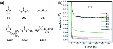 | ||
| Fig. 13 (a) Chemical structure of the baseline carbonate (EC and EMC), ethyl propylether (EPE), fluorinated cyclic carbonate (F-AEC), fluorinated linear carbonate (F-EMC), and fluorinated ether (F-EPE), (b) electrochemical stability of Gen 2 and fluorinated electrolytes E1 to E6 at 5.7 V using a 3-electrode electrochemical cell (Pt/Li/Li). Gen 2: 1.2 M LiPF6 EC/EMC (3/7), E1: 1.2 M LiPF6 in EC/EMC/F-EPE (2/6/2), E2: 1.2 M LiPF6 in EC/EMC/F-EPE (2/5/3), E3: 1.2 M LiPF6 in F-AEC/EMC/F-EPE (2/6/2), E4: 1.2 M LiPF6 in F-AEC/EC/EMC/F-EPE (1/1/6/2), E5: 1.2 M LiPF6 in F-AEC/F-EMC/F-EPE (2/6/2), E6: 1.2 M LiPF6 in EC/F-EMC/F-EPE (2/6/2). Reproduced with permission.18 | ||
The use of sulfone as an electrolyte solvent is expected to obtain a wide electrochemical stability window for electrolytes. Indeed, sulfone-based electrolytes exhibited high anodic stability without an appreciable oxidation current up to 5.0 V.21,73–75 The Amine group investigated the flammability and electrochemical performance of a tetramethyl sulfone (TMS)-based electrolyte in a LTO/LNMO cell. In their study, because the TMS solvent undergoes a detrimental reaction toward the graphite anode, LTO without significant electrolyte decomposition within the operating potential was utilized as the anode.76 Additionally, to overcome the poor wettability of the TMS solvent toward the commercially available separator, ethyl methyl carbonate (EMC) was blended with TMS. A high-voltage LNMO cathode coupled with a LTO anode exhibited excellent cycling stability in the TMS/EMC-based electrolyte during 1000 cycles at a rate of 2 C (current density of 240 mA g−1). This electrolyte could be a promising candidate for highly safe batteries because it is less flammable compared to conventional electrolytes. Because sulfone solvents are more stable toward electrochemical oxidation at high voltages relative to carbonate solvents, they will not form protective surface films, which can alleviate the dissolution of transition metal ions, on the LNMO cathode. Demeaux et al. reported that sulfones are promising solvents for high-voltage cathodes in LIBs, although they cannot prevent the dissolution of Mn2+ and Ni2+ in the electrolyte due to the lack of surface films forming on the LNMO cathode.77 Note that sulfone-based electrolytes must include an SEI former for their successful application in cells with graphite anodes.
The Angell group observed that the all sulfone-based electrolyte ethyl methyl sulfone (EMS)/fluoromethyl sulfone (FMS) (see the chemical structure of sulfone-based solvents in Fig. 14(a))/1 M LiPF6 provided a reasonable cycling property for the graphite anode, although considerable capacity fading of the LNMO cathode occurred during cycling between 3.5 and 4.9 V.78 This result can be explained by comparing the anodic stability between EMS/DMC/1 M LiPF6 and EMS/FMS/1 M LiPF6. As clearly shown in Fig. 14(b) and (c), an appreciable anodic current at approximately 4.9 V was observed for the EMS/FMS/1 M LiPF6 electrolyte. This result indicates that FMS is not stable at high voltages.
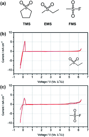 | ||
Fig. 14 (a) Structures of typical sulfone solvents. Cyclic voltammograms of 1 M LiPF6 in (b) EMS/DMC (1![[thin space (1/6-em)]](https://www.rsc.org/images/entities/char_2009.gif) : :![[thin space (1/6-em)]](https://www.rsc.org/images/entities/char_2009.gif) 1 by wt) and (c) EMS/FMS (1 1 by wt) and (c) EMS/FMS (1![[thin space (1/6-em)]](https://www.rsc.org/images/entities/char_2009.gif) : :![[thin space (1/6-em)]](https://www.rsc.org/images/entities/char_2009.gif) 1 by wt). Scan rate: 5 mV s−1. Pt as the working and counter electrodes and Li as the reference electrode. Reproduced with permission.78 1 by wt). Scan rate: 5 mV s−1. Pt as the working and counter electrodes and Li as the reference electrode. Reproduced with permission.78 | ||
3. Oxidative additives for LiNi0.5Mn1.5O4
Several approaches have been explored for developing suitable electrolytes for high-voltage LNMO cathodes in LIBs. To mitigate the oxidative decomposition of electrolytes at high voltages, sulfone-based solvents, ionic liquids, and dinitrile solvents with high anodic stabilities have been explored.21–24 Unfortunately, these solvents suffer from high intrinsic viscosities and severe reductive decomposition on carbonaceous anode materials. According to recent reports, the formation of stable artificial surface films through the use of additives in the electrolytes is considered to be an effective and economic strategy for stabilizing the LNMO cathode–electrolyte interface.71Lithium bis(oxalato)borate (LiBOB) (Fig. 9) is recognized as an effective salt-type additive and salt that forms a stable solid electrolyte interphase (SEI), not only on Si electrodes but also on those based on graphite.79–81 Recently, our group and the Lucht group investigated the use of LiBOB as a salt-type additive for the formation of protective surface films on LNMO cathodes.67 We found that the slightly high polarization induced by the LiBOB-derived SEI during the charge and discharge process may pose unavoidable problems, such as inferior rate capability. Because the SEI against unwanted cathode–electrolyte reactions is expected to improve the electrochemical properties of LNMO cathodes, the nature of the SEI on the cathode is of critical importance. Lucht et al. reported that when the Li/LNMO half-cell was cycled between 3.0 V and 4.9 V, 0.25% LiBOB resulted in a significant improvement in the discharge capacity retention and cycling efficiency of the cell.82
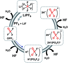
Although remarkable improvements in the electrochemical performance of Li/LNMO half-cells have been achieved, considerable capacity fading of full-cells with a graphite anode still occurs because of the metal (Mn and Ni) ions dissolved from the LNMO cathode in LiPF6-based electrolytes. Because labile P–F bonds are highly reactive toward trace amounts of moisture in the electrolyte solution, the LiPF6 salt readily undergoes hydrolysis reaction: LiPF6 (sol.) + H2O → POF3 (sol.) + LiF (s) + 2HF (sol.) and PF5 (sol.) + H2O → POF3 (sol.) + 2HF (sol.).83–86 The resulting HF may promote the dissolution of Mn/Ni from the cathode. The consumption of electrons via the reduction of dissolved metal ions on the graphite anode results in a reduction in the reversible capacity, and the deposited metal induces undesirable side reactions at the anode.87,88 This is the main factor that limits the commercialization of high-voltage LNMO cathodes. It is clear that developing novel electrolytes is an immediate technological solution for high-performance LIBs with a high-voltage cathode and graphite anode.
To improve the anodic stability of the electrolyte and to facilitate salt dissociation, the Sun group synthesized a new ortho-chelated salt: lithium bis(monofluoromalonato)borate (LiBFMB) (Fig. 9) modified from the LiBOB salt.89 Although LiBFMB salt dissolved in EC/DMC/DEC (1/1/1 by vol.) exhibits enhanced oxidation stability up to 5.2 V vs. Li/Li+, the LiBFMB salt resulted in severe electrolyte decomposition at the LNMO cathode and inferior cycling performance compared to LiBOB- and LiPF6-based electrolytes. Additionally, they reported that the Li/LNMO half-cell with the LiFBMB salt exhibited reasonable cycling stability when PC, which has a high dielectric constant and high anodic stability compared to DMC and DEC solvents, was used as the solvent.
It has been reported that the addition of LiBOB to the electrolyte leads to the formation of a protective film on the graphite anode and LNMO cathode and significantly improves the discharge capacity retention of the graphite/LiNi0.42Fe0.08Mn1.5O4 (LNFMO) full cell at 45 °C.69 This is because the LiBOB additive forms a more robust and stable SEI layer on the graphite anode, thereby avoiding the problem that originates from the dissolution of Mn, as shown in Fig. 15. Moreover, the amount of Mn that dissolved out of fully delithiated LNFMO cathodes was monitored when stored in reference and LiBOB-containing electrolytes at 60 °C for one month. Interestingly, the amount of Mn that dissolved out of the LNFMO cathode stored in the reference electrolyte was approximately 1.3 wt%, whereas for the cathode stored in the LiBOB-containing electrolyte, the amount of Mn that dissolved out of the cathode was reduced to 0.2 wt%. They demonstrated that the decrease in the dissolution of Mn during storage at 60 °C occurred because the LiBOB effectively traps the PF5 in the electrolyte and prevents the oxidative decomposition of solvents catalyzed by PF5 attack, as illustrate in Fig. 15.69
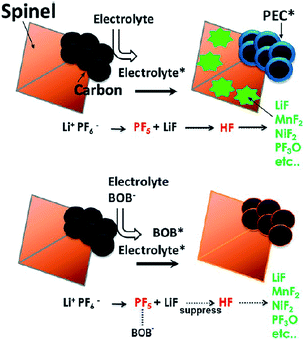 | ||
| Fig. 15 Proposed mechanism of the LiBOB additive for the improvement in electrochemical performance of the spinel high-voltage LNFMO cathode. Reproduced with permission.69 | ||
The Li/LNMO half-cells with the LiBOB-containing electrolyte exhibited a slightly reduced initial Coulombic efficiency and slightly higher polarization at the end of the charge and discharge process compared to the LiBOB-free electrolyte.73 This result is because the LiBOB decomposition reaction results in a capacity loss due to the consumption of Li ions and results in the formation of a more resistive SEI on the cathode surface. Nevertheless, when LiBOB was added to the electrolyte, the discharge capacity retention of LNMO was significantly improved from 66.9 to 78.7% after 80 cycles at 60 °C. Based on XPS studies, we confirmed that a LiBOB-originated SEI is formed on the LNMO cathode surface. The C 1s peak at 288.8 eV attributed to semi-carbonate-like species appeared as a result of the oxidative decomposition of a LiBOB additive.
Recently, Abraham et al. proposed the first plausible mechanism for the LiBOB-derived SEI on the cathode surface, which is depicted in Fig. 16.90 It is expected that LiBOB readily loses an electron on the high-voltage cathode surface. The subsequent loss of two equivalents of CO2 from the compound resulting from LiBOB ring-opening generates an oxalatoborate radical (Fig. 16). This radical can react with EC in the electrolyte and forms polycarbonate-like oligomers on the cathode surface. LiBOB, which forms a surface film with carbonyl-rich species (semi-carbonate-like compounds) on a graphite anode, has been identified as a very effective reducible additive.91
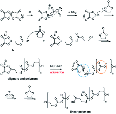 | ||
| Fig. 16 Possible mechanism for the LiBOB oxidative decomposition products. Reproduced with permission.90 | ||
Similarly, the LiBOB-derived SEI formed on the high-voltage cathode contains semi-carbonate-like species.70,90 The comparison of Fig. 16 and 17 clearly shows that the detailed chemical structures of the SEI layers formed via the reduction and oxidation of LiBOB on the anode and cathode are different.
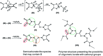 | ||
| Fig. 17 Possible products by the LiBOB reductive decomposition. Reproduced with permission.91 | ||
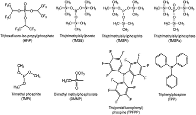
Very recently, Manthiram et al. reported that significant breakthroughs in the full cell configuration with the LNMO cathode can be achieved by developing functional liquid electrolytes with no or less reactivity toward the LNMO cathode and without metal-ion dissolution.87 The requirement for high voltage-compatible electrolytes has become a high priority for high-voltage LNMO cathodes in LIBs. To improve the electrochemical performance of 5 V-class LNMO cathode materials, we reported a highly promising organophosphorus compound with an organic substituent, tris(trimethylsilyl) phosphite (TMSP) with a phosphorous(III) atom (Fig. 7).92 HF produced at each hydrolysis step easily reacts with the SEI component such as Li2CO3 (Li2CO3 → LiF (s) + H2O (sol.) + CO2↑) and causes the breakdown of the SEI layer on the cathode surface. Moreover, HF can promote the dissolution of metal ions out of the LiNi0.5Mn1.5O4 cathode, i.e., LiNi0.5Mn1.5O4 + xHF → Li1−xNi0.5Mn1.5O4 + xLiF (s) + Mn2+ (sol.) + xH2O (sol.) and the resulting Mn2+ ions, which are very soluble in the electrolyte, migrates toward the anode inducing the delithiation of the anode and the formation of additional SEI. Hydrolysis reactions of LiPF6 that accompany the formation of HF are clearly shown in Fig. 18.93
Recent our investigation revealed that TMSP reduces the decomposition of LiPF6 by hydrolysis, effectively removes the HF from promoting the metal dissolution from the cathode, and forms a protective layer on the cathode surface against severe electrolyte decomposition at high voltages (Fig. 19(a)).92 Indeed, the characteristic resonance of HF at −153 ppm apparently disappeared in the electrolyte with TMSP additive in the 19F NMR spectrum of Fig. 19(b). Moreover, remarkable improvements in the cycling stability and rate capability of high-voltage cathodes were achieved in the TMSP-containing electrolyte. The discharge capacity retention of Li/LNMO half-cell was 73% in the reference electrolyte after 100 cycles at 60 °C, whereas the TMSP-added electrolyte retained 90% of its initial discharge capacity. It was also found that the LNMO cathode in the TMSP-containing electrolyte delivered a superior discharge capacity of 105 mA h g−1 at a high rate of 3 C and an excellent capacity retention of 81% with a high Coulombic efficiency of greater than 99.6% in a graphite/LNMO full cell after 100 cycles at 30 °C was achieved. Previously, Cho et al. reported the beneficial effect of succinic anhydride (SA) and 1,3-propane sultone (PS) additives (Fig. 1) on the electrochemical performance of graphite/LNMO full cells.94 They reported that vinylene carbonate (VC), which has been identified as the most efficient anode SEI former, undergoes irreversible oxidation at the LNMO cathode and results in severe capacity fading of full cells. This result was confirmed in our previous study.92 Indeed, the discharge-capacity fading of LNMO half-cells containing VC additive was much greater than that of cells with the reference electrolyte in subsequent cycles at 60 °C. Moreover, a comparison of the initial charge and discharge profiles of the Li/LNMO half-cells in electrolytes with and without the VC additive at 30 °C clearly demonstrated that significant overcharging of the LNMO cathode occurred in the VC-containing electrolyte when charged to 5.0 V. Unfortunately, the VC additive continuously underwent severe oxidative decomposition at potentials greater than 4.8 V at 60 °C. This decomposition was due to the VC additive being prone to oxidation at a charging potential of 5.0 V because of its relatively high HOMO energy level compared to that of conventional carbonate solvents such as EC. Although preferential reduction of VC as the most effective additive prior to carbonate solvents resulted in the formation of a stable SEI on the anode, the VC additive is not suitable for use in cells with high-voltage LNMO cathodes.
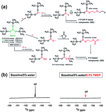 | ||
| Fig. 19 (a) Proposed mechanisms for electrochemical oxidative decomposition of TMSP and for the unique function of TMSP scavenging HF from the electrolyte. (b) 19F NMR spectra of the electrolyte with and without TMSP. Reproduced with permission.92 | ||
Very recently, glutaric anhydride (GA) (Fig. 1) has been investigated as an electrolyte additive for improving the electrochemical performance of LNMO/LTO full cells.95 Interestingly, the amount of inorganic species (LiF, phosphates, fluorophosphates) in the surface film formed on the LNMO cathode cycled in the GA-containing electrolyte for 118 cycles was relatively low compared with the additive-free electrolyte. Moreover, in the case of the GA-containing electrolyte, the intensity of the peak corresponding to organic species (O![[double bond, length as m-dash]](https://www.rsc.org/images/entities/char_e001.gif) C–O, C
C–O, C![[double bond, length as m-dash]](https://www.rsc.org/images/entities/char_e001.gif) O, C–O–C, –CH2), which was not observed for the pristine LNMO cathode, was much stronger compared to that for the additive-free electrolyte.
O, C–O–C, –CH2), which was not observed for the pristine LNMO cathode, was much stronger compared to that for the additive-free electrolyte.
Various phosphorous-containing additives that form a protective layer on the high-voltage LNMO cathode have been explored. To preserve carbonate-based electrolytes on 5 V-class cathode surfaces at room temperature, a highly fluorinated phosphate ester additive, tris(hexafluoro-iso-propyl) phosphate (HFiP) (Fig. 7), was investigated.96
Fig. 20(a) compares the cycling stabilities of Li/LNMO half cells in the reference and HFiP-containing electrolytes during 200 cycles. A significant improvement in the capacity retention of Li/LNMO half cells was observed for the HFiP-containing electrolyte compared with the reference electrolyte. It can be hypothesized that the combination of the functional additive and the surface modification of the cathode material leads to an additional improvement in the electrochemical performance of the LNMO cathode. To successfully apply the developed electrolyte to a full cell, the additive for a high-voltage cathode should have good compatibility with the anode. The Xu group selected mesocarbon microbead (MCMB) for use as the anode in commercialized Li-ion batteries to investigate the cathodic property of the HFiP additive on the graphite anode and PC as the solvent, which fails to form a stable anode SEI to stop extensive graphene exfoliation.71
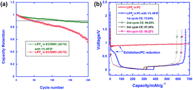 | ||
| Fig. 20 (a) Cycling performance of LiNi0.5Mn1.5O4 in the reference and HFiP-containing electrolytes. Percent capacity retention is shown for easy comparison. (b) Voltage profiles of the graphite anodes in the PC-based electrolyte with and without 1% HFiP additive. Reproduced with permission.96 | ||
The presence of the HFiP additive in PC effectively suppressed the co-intercalation of PC and exfoliation of graphene layers, and reversible Li+-intercalation chemistry was eventually realized in the PC-based electrolyte (Fig. 20(b)). As clearly shown in Fig. 20(b), the initial four cycles demonstrated that the HFiP-derived SEI serves as a protective film for the graphite anode. This beneficial effect of the HFiP additive on the graphite anode is expected to provide good electrochemical performance for full cells that employ graphite anodes.
Li et al. reported that the use of tris(trimethylsilyl)phosphate (TMSPa) (Fig. 7) as an additive improves the cycling performance of Li/LNMO half-cells at 55 °C.97 They proposed that the TMSPa-derived SEI prevents the oxidative decomposition of the electrolyte on the cathode at high voltages and suppresses the dissolution of Mn and Ni from the LNMO cathode. The Li group examined the effect of tris(pentafluorophenyl)phosphine (TPFPP) (Fig. 7) as an additive on the electrochemical performance of Li/LNMO half-cells.98 They found that the LNMO cathode in the TPFPP-containing electrolyte had a lower leakage current than that in the reference electrolyte at 5.2 V vs. Li/Li+. The comparison of the XPS results for the surface chemistry of the LNMO cathode cycled in the electrolyte with and without the TPFPP additive clearly shows that a pronounced LiF peak (684.5 eV) is observed for the cathode cycled in the TPFPP-containing electrolyte, whereas there is no the LiF peak for the cathode cycled in the reference electrolyte (Fig. 21(a)). This result indicates that the TPFPP additive forms a protective film on the cathode and effectively inhibits the decomposition of the salt at high voltages. This result is consistent with the Lucht group's result (Fig. 21(b)), in which the LNMO cathode cycled in the reference electrolyte (EC/EMC (3/7, v/v)/1 M LiPF6) exhibited a strong LiF peak.99
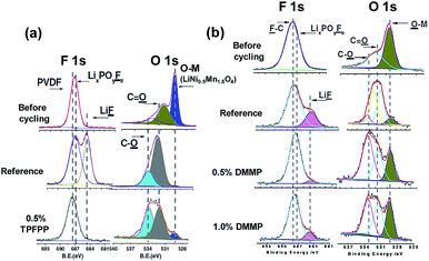 | ||
| Fig. 21 F 1s and O 1s XPS spectra of (a) LiNi0.5Mn1.5O4 electrode before and after cycled in reference and TPFPP-added electrolyte (the cycled cathodes were obtained from the Li/LNMO half cells after 55 cycles) and (b) LiNi0.5Mn1.5O4 electrode before and after cycled with reference and DMMP-added electrolyte, (the cycled cathodes were obtained from the Li/LNMO half cells after 50 cycles). Reproduced with permission.98,99 | ||
Dimethyl methylphosphonate (DMMP) (Fig. 7) was investigated as an oxidative additive to produce a protective surface film and improve the cycling performance of the LNMO cathode. The Li/LNMO half-cell with 0.5% DMMP additive exhibited superior capacity retention for 50 cycles compared to the 1% DMMP-containing and reference electrolytes. In addition, the peak corresponding to the metal oxide (O-M) of the LNMO cathode materials in the O 1s spectra was weak in the case of the reference electrolyte (Fig. 21(b)). This result is attributed to a very thick surface film that formed from the decomposition of the reference electrolyte at the LNMO cathode, thereby blocking the O signal from the cathode.98,99
F Interfacial properties of Li-rich cathodes: xLi2MnO3·(1 − x)LiMO2
1. Surface chemistry of Li-rich cathodes
To achieve high-energy density Li-ion batteries, many researchers have focused on developing Li-rich cathode materials represented by xLi2MnO3(1 − x)LiMO2 (ref. 9, 19, 100 and 101) due to their high average operating voltages (>3.5 V vs. Li/Li+)19 and high reversible capacities (>200 mA h g−1).19,20,102 However, the practical application of Li-rich cathodes in Li-ion batteries is still quite challenging because Li-rich cathodes suffer from the following problems: (i) high charging voltage, (ii) voltage decay as a result of the structural transformation from the layered phase to spinel phase, (iii) poor cycling stability, and (iv) inferior rate capability. First, the condition of charging to the voltage range of 4.6–4.8 V during the first charge9 results in severe oxidative decomposition of LiPF6/carbonate-based electrolytes occurring above 4.5 V vs. Li/Li+.17,71 This process consumes the limited Li+ source in a cell, forms a thick SEI layer on the cathode materials and will eventually disable the cell. In recent years, many researchers have reported significant improvements in the electrochemical performance of Li-ion cells through the use of electrolyte additives, which suppress the undesirable decomposition of electrolyte on the cathode surface.103–108 The second critical problem of Li-rich cathodes is the phase transformation from a layered structure to a spinel-like structure, which results in an irreversible voltage decay during cycling.109–111 The phase transformation, which occurs as transition metal ions in the transition metal layer move into the Li layer, causes considerable capacity fading because transition metal ions in the Li layer impede the lithiation and delithiation process. Upon further cycling, the layered-to-spinel transformation proceeds gradually from the surface to bulk as the cycling process progresses, as illustrated in Fig. 22.119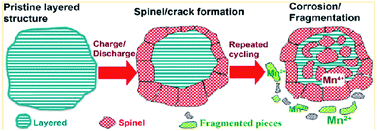 | ||
| Fig. 22 Schematic drawing of failure mechanism of Li-rich cathode during cycling. Reproduced with permission.111 | ||
The third challenge is the oxygen that evolves from the irreversible decomposition of the Li2MnO3 component in the Li-rich cathode particles during charging to over 4.6 V.19 The resulting oxygen molecule may be electrochemically reduced to form active oxygen radicals (O2˙−). These oxygen radicals in the cells will attack carbonate solvents in the electrolyte. Freunberger et al.,112 Bruce et al.,113 and Kang et al.114 proposed that oxygen radicals lead to the decomposition of carbonate solvents, and Li2CO3 and various organic compounds as byproducts are generated. The formation of Li2CO3 on the cathode surface via the electrochemical reduction of oxygen molecules during the discharge process may disturb the reversible electrochemical reaction of the Li-rich cathode, and thus, capacity fading will occur. Finally, a thick SEI layer effectually prevents the decomposition of the electrolyte and the Li2CO3 formed by the electrolyte decomposition on the cathode materials may hinder the reversible redox reaction of the cathode at high C rates. Several strategies have been proposed to overcome these problems.
2. Oxidative additives for Li-rich cathodes
Notably, using electrolyte additives is a very efficient and economic means for obtaining the desired functionality. Among the various electrolyte additives, phosphite-based additives with a phosphorous(III) atom are expected to be oxidized prior to carbonate solvents in the electrolyte and to form a protective film on the cathode surface.Recently, substituted dioxaphosphinane was proposed as an oxidative additive, which can form a protective layer that effectively suppresses the oxidative decomposition of the electrolyte.107 As a result, the presence of 4-methyl-2-[(2,2,3,3,4,4,5,5-octafluoropentyl)oxy]-1,3,2-dioxaphosphinane (OA) (Fig. 23) in the electrolyte led to remarkable improvements in the Coulombic efficiency, discharge capacity retention of a graphite/Li-rich cathode (Li1.2Ni0.18Mn0.53Co0.09O2) cell, and thermal stability of a delithiated cathode. The comparison of the electrochemical performance of graphite/Li1.2Ni0.18Mn0.53Co0.09O2 cell with OA or OA-oxide clearly showed that OA-oxide containing a phosphorous atom with the maximal degree of oxidation (V) is not effective for stabilizing the Li1.2Ni0.18Mn0.53Co0.09O2 cathode–electrolyte interface in a cell.107 Interestingly, it was reported the OA additive does not greatly affect exothermic reactions between fully lithiated graphite and the electrolyte.
Xiang et al. reported the effect of trimethyl phosphite (TMPi) on the Li-rich layered oxide cathode Li1.2Mn0.54Ni0.13Co0.13O2.104 The Li/Li1.2Mn0.54Ni0.13Co0.13O2 half-cell with TMPi-containing electrolyte exhibited good capacity retention of 81.3% after 100 cycles and a superior rate capability of 90 mA h g−1 at a rate of 10 C compared with the reference electrolyte. The TMPi-derived SEI on the cathode surface could alleviate the exothermic reaction between the delithiated cathode and the electrolyte.104 To improve the electrochemical performance of the Li[Li0.2Mn0.56Ni0.16Co0.08]O2 cathode, Yang et al. examined the use of tris(hexafluoro-iso-propyl)phosphate (HFiP) (Fig. 7) as a cathode SEI former, which was previously utilized for a 5 V-class spinel LNMO cathode.115
A comparison of the midpoint voltages of cathodes, which is an important parameter for high energy density Li-ion batteries, is displayed in Fig. 24(a). At the 100th cycle, the midpoint voltage during discharge for a cathode material cycled in the additive-free electrolyte was 3.31 V. The Li[Li0.2Mn0.56Ni0.16Co0.08]O2 cathode cycled in the electrolyte with 1% and 2% HFiP additive exhibited relatively high midpoint voltages of 3.45 V and 3.43 V, respectively. This result suggests that the addition of HFiP as an additive stabilizes the Li[Li0.2Mn0.56Ni0.16Co0.08]O2 cathode–electrolyte interface. Direct evidence for the surface film formed by HFiP additive is given by the TEM analysis of the cycled Li[Li0.2Mn0.56Ni0.16Co0.08]O2 cathodes in electrolytes with and without HFiP additive, as shown in Fig. 24(b) and (c). The TEM images reveal that an amorphous SEI layer exists on the surface of the cathode particles. The Li[Li0.2Mn0.56Ni0.16Co0.08]O2 cathode cycled in the HFiP-containing electrolyte (Fig. 24(c)) is covered by a continuous and uniform SEI layer on the electrode with a thickness of less than 5 nm compared with that in reference electrolyte. To suppress side reactions with the electrolyte at the Li[Li0.2Mn0.54Ni0.13Co0.13]O2 cathode, the Wang group introduced tris(trimethylsilyl)phosphate (TMSPa) as a cathode SEI former, which was utilized for LiNi0.5Co0.2Mn0.3O2 in the voltage range of 3.0–4.5 V.106 The Si 2p XPS result confirmed that the TMSP additive contributed to the formation of a SEI on the surface of the Li[Li0.2Mn0.54Ni0.13Co0.13]O2 cathode. The peak attributed to Si–O was clearly observed at 102.3 eV. The thermal stability of the SEI at elevated temperatures is a very important factor for ensuring the high-temperature performance of cells. The use of 1,3,5-trihydroxybenzene (THB) (Fig. 23) as an additive to form a protective film on the cathode could improve the long-term cycling stability of graphite/Li1.10Mn0.43Ni0.23Co0.23O2 full cells at 60 °C. More importantly, a very high Coulombic efficiency of greater than 99.5%, which is vital for practical applications, was obtained during 200 cycles.116 In addition, the Mn 2p3/2 peak intensity was increased for the cathode cycled in the additive-free electrolyte. This result indicates that the cathode surface is more exposed by the breakdown of the SEI and that the SEI formed by the additive-free electrolyte is thermally unstable.
 | ||
| Fig. 24 Midpoint voltage of cells at a current density of 180 mA g−1 in the voltage range of 2.0–4.6 V with electrolytes containing 0%, 1% and 2% HFiP additive. TEM images of Li[Li0.2Mn0.56Ni0.16Co0.08]O2 cathodes in the electrolyte (b) without and (c) with HFiP additive at 18 mA g−1 after 1 cycle. Reproduced with permission.115 | ||
Widely used electrolyte additives such as VC, VEC and FEC are not suitable for Li-rich cathodes, such as Li1.2Ni0.15Mn0.55Co0.1O2, that are cycled at high voltages of >4.5 V vs. Li/Li+.117
Abraham et al. reported that the graphite/Li1.2Ni0.15Mn0.55Co0.1O2 full cell with 0.5 wt% perfluorooctyl-substituted ethylene carbonate (PFO-EC) (Fig. 25(a)) delivers a higher discharge capacity of 172 mA h g−1 (66% capacity retention of the initial discharge capacity) at a current density of 75 mA g−1 than that of the reference electrolyte.117 They found that the PEO-EC additive serves the protective layer for the graphite anode and the Li1.2Ni0.15Mn0.55Co0.1O2 cathode, as depicted in Fig. 25(b).
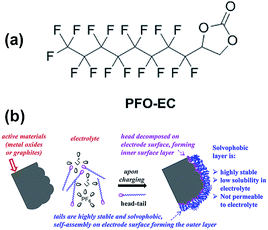 | ||
| Fig. 25 (a) Chemical structure of PFO-EC. (b) Schematic for the formation of double-layer passivation films by decomposition of the head group on the cathode (or anode) surface forming an inner layer and self-assembly of tails on these inner layers forming a solvophobic outer layer. Reproduced with permission.117 | ||
Lithium difluoro(oxalate)borate (LiFOB), which has been intensively investigated as a reducible additive for the anode in Li-ion batteries, was utilized for the Li1.2Ni0.15Mn0.55Co0.1O2 cathode.118 The Li/Li1.2Ni0.15Mn0.55Co0.1O2 half-cell with 2 wt% LiFOB additive exhibited a highly reduced leakage current at a constant voltage of 4.7 V. This is because LiFOB preferentially oxidizes to form the SEI on the cathode surface. The surface chemistry of the cathode as a result of the oxidative decomposition of LiFOB, which electrochemically oxidizes at 4.35 V vs. Li/Li+,119 is shown in Fig. 26.118
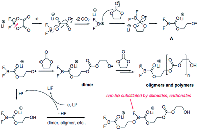 | ||
| Fig. 26 Possible mechanism of the oxidative decomposition of LiFOB additive on the high-voltage cathode. Reproduced with permission.118 | ||
Because the LiFOB salt-type additive can easily lose an electron on the cathode surface when full cells are charged to 4.6 V, ring opening of LiFOB occurs along with two equivalents of CO2 and the generation of a difluoroborane radical. This active radical may react with carbonate solvents such as EC and produce polycarbonate species on the cathode surface. The resulting LiFOB-derived SEI inhibited electrolyte oxidation on the Li1.2Ni0.15Mn0.55Co0.1O2 cathode and reduced metal ion dissolution from the cathode. Importantly, the LiFOB additive acted as a bi-functional additive for the high-voltage cathode and anode.
Recently, we clearly showed that LiBOB serves as an oxidative additive to prevent the undesirable decomposition of the electrolyte on the surface of Li1.17Ni0.17Mn0.5Co0.17O2 cathodes in half and full cells with graphite anodes.108 Remarkable improvements in the cycling stability and rate capability of Li1.17Ni0.17Mn0.5Co0.17O2 cathodes were achieved in the LiBOB-containing electrolyte. In particular, the discharge capacity retention of the Li1.17Ni0.17Mn0.5Co0.17O2 cathode was 28.6% in the reference electrolyte, whereas the LiBOB-containing electrolyte retained 77.6% of its initial discharge capacity after 100 cycles at 60 °C. In addition, the LiBOB-derived SEI formed on the Li1.17Ni0.17Mn0.5Co0.17O2 cathode allowed rapid charge transfer at high C rates, whereas the SEI formed by the additive-free electrolyte impeded the diffusion of Li ions. The Abraham group confirmed the positive impact of LiBOB on the Li-rich cathode Li1.2Ni0.15Mn0.55Co0.1O2. They proposed a detailed mechanism for the oxidative decomposition of LiBOB and noted that the combination of electrolyte additives, LiBOB + LiFOB, leads to further improved electrochemical performance of graphite/Li1.2Ni0.15Mn0.55Co0.1O2 full cells.
As an oxygen scavenger, the phosphorous derivative triethyl phosphite (TEPi) (Fig. 23) was introduced into the graphite/Li1.167Ni0.233Co0.1Mn0.467Mo0.033O2 full cell.117 It was found that the use of TEP as an additive not only leads to an improvement in the cycling performance of a full cell with the Li1.167Ni0.233Co0.1Mn0.467Mo0.033O2 cathode but also to a decrease in the internal pressure of the cells. The results of a 31P NMR study confirmed that the use of TEP as an additive with a non-maximal phosphorous atom(III) easily reacts with O2 gas to form relatively stable phosphate compounds that are soluble in the electrolyte (Fig. 27) and reduces the internal pressure via the O2 gas that evolves out of the cathode material.120
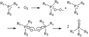 | ||
| Fig. 27 Schematic representation for oxygen-absorbing reaction by phosphorus compound. Reproduced with permission.117 | ||
These results suggest that reduction of the O2 gas evolved from the activation of Li2MnO3 to superoxide anion (O2−)18 can be avoided; thus, unwanted decomposition of electrolyte solvents by O2− attack (carbonate solvent + O2− → linear lithium alkyl carbonate, Li2CO3)19 can be alleviated and the reaction between O2 and Li to form Li2O20 during the charging process can be minimized. As a result, the severe capacity fading of Li1.167Ni0.233Co0.1Mn0.467Mo0.033O2 cathodes could be prevented.
G Conclusions
In this review, we have demonstrated the critical issues such as the dissolution of metal ions out of the cathode, and undesirable interfacial phenomena between the high-voltage cathode and the electrolyte. Until now, substantial efforts have been made in the development of suitable oxidative additives and high-voltage solvents to design advanced electrolytes for cathodes with high operating voltage and/or showing severe metal ion dissolution in Li-ion batteries. For the practical uses of electrolytes in high-voltage cathodes, the following promising strategies should be considered: (i) HF scavenger minimizing the HF content in a cell scavenger, (ii) high-voltage electrolytes formulated with the solvents showing superior anodic stability, (iii) oxidative additives with relatively high HOMO energy to form the stable SEI layer protecting the cathode surface at high voltages.(1) Spinel LiMn2O4 (LMO) cathodes exhibited considerable manganese (Mn) dissolution at elevated temperatures by the HF attack and the oxidation (electron donating tendency) of PF6− anions at a highly delithiated cathode. The use of oxidative additives that make protective films preventing the Mn dissolution could improve the cycling stability of graphite/LMO full cells at 60 °C. Of course, to fulfill reasonable cycling performance of full cells with LMO cathodes, the addition of a bi-functional or reducible additive should be considered for the formation of the SEI layer protecting the graphite anode.
(2) Among various approaches examined for high-voltage cathodes, the use of oxidative organic-based, phosphorous-based, and salt-type additives is a promising, economic, and feasible mean to alleviate the oxidative decomposition of the electrolyte at high voltages (>4.3 V vs. Li/Li+) and to preserve the electrochemical performance of high-voltage cathodes including LiCoO2, Lix(NiaCobMn1−a−b)O2, LiNi0.5Mn1.5O4, and Li-rich cathodes represented by xLi2MnO3(1 − x)LiMO2. Using oxidative additives for build-up of a robust and stable artificial SEI layer on the cathode as a barrier to further electrolyte decomposition could ensure the long-term cycle life of full cells with high-voltage cathodes. Moreover, intriguing functions of boron-based additives dissolving highly resistive LiF from the SEI layer on the cathode and of phosphorous(III)-based additives eliminating the HF that promotes dissolution of metal ions from the cathode have been described. Especially, LiBOB and LiFOB additives for full cells coupled with high-voltage cathodes are attracting a great deal of attention as salt-type additives because they have the unique feature preserving the electrochemical performance of both electrodes in a cell.
Acknowledgements
This research was supported by the IT R&D program of MKE/KEIT (KI001810039182, development of 5 V cathode material which capacity is 125 mA h g−1 and high voltage electrolyte which decomposition is over 5 V for lithium secondary battery) and by a grant from the Energy Efficiency & Resources of the Korea Institute of Energy Technology Evaluation and Planning (Project no. 20112010100140) funded by the Korean Ministry of Knowledge Economy. This study was partly supported by a National Research Foundation of Korea Grant funded by the Korean Government (MEST) (NRF-2013-C1AAA001-0030538).Notes and references
- J.-M. Tarascon and M. Armand, Nature, 2001, 414, 359 CrossRef CAS PubMed
.
- N.-S. Choi, Z. Chen, S. A. Freunberger, X. Ji, Y.-K. Sun, K. Amine, G. Yushin, L. F. Nazar, J. Cho and P. G. Bruce, Angew. Chem., Int. Ed., 2012, 51, 9994 CrossRef CAS PubMed
.
- B. Dunn, H. Kamath and J.-M. Tarascon, Science, 2011, 334, 928 CrossRef CAS PubMed
.
- D. Aurbach, K. Gamolsky, B. Markovsky, Y. Gofer, M. Schmidt and U. Heider, Electrochim. Acta, 2002, 47, 1423 CrossRef CAS
.
- D. Aurbach, J. S. Gnanaraj, W. Geissler and M. Schmidt, J. Electrochem. Soc., 2004, 151, A23 CrossRef CAS
.
- H. Ota, Y. Sakata, A. Inoue and S. Yamaguchi, J. Electrochem. Soc., 2004, 151, A1659 CrossRef CAS
.
- N.-S. Choi, K. H. Yew, K. Y. Lee, M. Sung, H. Kim and S.-S. Kim, J. Power Sources, 2006, 161, 1254 CrossRef CAS
.
- J. C. Burns, R. Petibon, K. J. Nelson, N. N. Sinha, A. Kassam, B. M. Way and J. R. Dahn, J. Electrochem. Soc., 2013, 160, A1668 CrossRef CAS
.
- C. S. Johnson, J. S. Kim, C. Lefief, N. Li, J. T. Vaughey and M. M. Thakeray, Electrochem. Commun., 2004, 6, 1085 CrossRef CAS
.
- N. Tran, L. Coguennec, M. Menetrier, F. Weil, P. Biensan, C. Jordy and C. Delmas, Chem. Mater., 2008, 20, 4815 CrossRef CAS
.
- J.-H. Lim, H. Bang, K.-S. Lee, K. Amine and Y.-K. Sun, J. Power Sources, 2009, 189, 571 CrossRef CAS
.
- Q. Wu, W. Lu, M. Miranda, T. K. Honaker-Schroeder, K. Y. Lakhsassi and D. Dees, Electrochem. Commun., 2012, 24, 78 CrossRef CAS
.
- H. Duncan, Y. Abu-Lebdeh and J. Davidson, J. Electrochem. Soc., 2010, 157, A528 CrossRef CAS
.
- M. Aklalouch, J. M. Amarilla, R. M. Rojas, I. Saadoune and J. M. Rojo, J. Power Sources, 2008, 185, 501 CrossRef CAS
.
- M. Aklalouch, R. M. Rojas, J. M. Rojo, I. Saadoune and J. M. Amarilla, Electrochim. Acta, 2009, 54, 7542 CrossRef CAS
.
- D. W. Shin and A. Manthiram, Electrochem. Commun., 2011, 13, 1213 CrossRef CAS
.
- L. Yang, B. Ravdel and B. Lucht, Electrochem. Solid-State Lett., 2010, 13, A95 CrossRef CAS
.
- Z. Zhang, L. Hu, H. Wu, W. Weng, M. Koh, P. C. Redfern, L. A. Curtiss and K. Amine, Energy Environ. Sci., 2013, 6, 1806 CAS
.
- N. Yabuuchi, K. Yoshii, S.-T. Myung, I. Nakai and S. Komaba, J. Am. Chem. Soc., 2011, 133, 4404 CrossRef CAS PubMed
.
- S. Hy, F. Felix, J. Rick, W.-N. Su and B. J. Hwang, J. Am. Chem. Soc., 2014, 136, 999 CrossRef CAS PubMed
.
- K. Xu and C. A. Angell, J. Electrochem. Soc., 2002, 149, A920 CrossRef CAS
.
- N. Shao, X.-G. Sun, S. Dai and D. Jiang, J. Phys. Chem. B, 2012, 116, 3235 CrossRef CAS PubMed
.
- V. Borgel, E. Markevich, D. Aurbach, G. Semraub and M. Schmidt, J. Power Sources, 2009, 189, 331 CrossRef CAS
.
- Y. Abu-Lebdeh and I. Davidson, J. Electrochem. Soc., 2009, 156, A60 CrossRef CAS
.
- X. X. Zuo, C. J. Fan, X. Xiao, J. S. Liu and J. M. Nan, J. Power Sources, 2012, 219, 94 CrossRef CAS
.
- K. Abe, Y. Ushigoe, H. Yoshitake and M. Yoshio, J. Power Sources, 2006, 153, 328 CrossRef CAS
.
- J.-N. Lee, G.-B. Han, M.-H. Ryou, D. J. Lee, J. Song, J. W. Choi and J.-K. Park, Electrochim. Acta, 2011, 56, 5195 CrossRef CAS
.
- N.-S. Choi, Y. Yao, Y. Cui and J. Cho, J. Mater. Chem., 2011, 21, 9825 RSC
.
- L. F. Wang, B. J. Fang and J. S. Chen, J. Power Sources, 2005, 150, 1 CrossRef CAS
.
- Y. Nishi, J. Power Sources, 2001, 100, 101 CrossRef CAS
.
- M. M. Thackeray, Y. Shao-Horn, A. J. Kahaian, K. D. Kepler, E. Skinner, J. T. Vaughey and S. A. Hackney, Electrochem. Solid-State Lett., 1998, 1, 7 CrossRef CAS
.
- T. Inoue and M. Sano, J. Electrochem. Soc., 1998, 145, 3704 CrossRef CAS
.
- I. H. Cho, S.-S. Kim, S. C. Shin and N.-S. Choi, Electrochem. Solid-State Lett., 2010, 13, A168 CrossRef CAS
.
- A. Du Pasquier, A. Blyr, P. Courjal, D. Larcher, G. Amatucci, B. Gérand and J.-M. Tarascon, J. Electrochem. Soc., 1999, 146, 428 CrossRef CAS
.
- H. Yamane, T. Inoue, M. Fujita and M. Sano, J. Power Sources, 2001, 99, 60 CrossRef CAS
.
- T. Aoshima, K. Okahara, C. Kiyohara and K. Shizuka, J. Power Sources, 2001, 97–98, 377 CrossRef CAS
.
- H. Tsunekawa, S. Tanimoto, R. Marubayashi, M. Fujita, K. Kifune and M. Sano, J. Electrochem. Soc., 2002, 49, A1326 CrossRef
.
- A. Blyr, A. D. Pasquier, G. Amatucci and J.-M. Tarascon, Ionics, 1997, 3, 321 CrossRef CAS
.
- N.-S. Choi, J.-T. Yeon, Y.-W. Lee, J.-G. Han, K. T. Lee and S.-S. Kim, Solid State Ionics, 2012, 219, 4 CrossRef
.
- J. W. Song, C. C. Nguyen, H. Choi, K. H. Lee, K. H. Han, Y. J. Kim, S. Choy and S. W. Song, J. Electrochem. Soc., 2011, 158, A458 CrossRef CAS
.
- G. B. Zhong, Y. Y. Wang, Z. C. Zhang and C. H. Chen, Electrochim. Acta, 2011, 56, 6554 CrossRef CAS
.
- H. W. Chan, J. G. Duh and H. S. Sheu, J. Electrochem. Soc., 2006, 153, A1533 CrossRef CAS
.
- K. Vediappan and C. W. Lee, Phys. Scr., T, 2010, 139, 014040 CrossRef
.
- H. B. Kang, S. T. Myung, K. Amine, S. M. Lee and Y. K. Sun, J. Power Sources, 2010, 195, 2023 CrossRef CAS
.
- K. Amine, J. Liu, I. Belharouak, S. H. Kang, I. Bloom, D. Vissers and G. Henriksen, J. Power Sources, 2005, 146, 111 CrossRef CAS
.
- Y. X. Guo, Z. G. Yin, Z. Y. Tao, X. H. Li and Z. X. Wang, J. Power Sources, 2008, 184, 513 CrossRef CAS
.
- I. B. Stojkovic, N. D. Cvjeticanin and S. V. Mentus, Electrochem. Commun., 2010, 12, 371 CrossRef CAS
.
- S. Komaba, T. Itabashi, T. Ohtsuka, H. Groult, N. Kumagai, B. Kaplan and H. Yashiro, J. Electrochem. Soc., 2005, 152, A937 CrossRef CAS
.
- S. Komaba, T. Ohtsuka, B. Kaplan, T. Itabashi, N. Kumagai and H. Groult, Chem. Lett., 2002, 31, 1236 CrossRef
.
- H. Ota, K. Shima, M. Ue and J.-I. Yamaki, Electrochim. Acta, 2004, 49, 565 CrossRef CAS
.
- M. Holzapfel, C. Jost, A. Prodi-Schwab, F. Krumeich, A. Wursig, H. Buqa and P. Novak, Carbon, 2005, 43, 1488 CrossRef CAS
.
- D. Aurbach, B. Markovsky, A. Rodkin, E. Levi, Y. S. Cohen, H.-J. Kim and M. Schmidt, Electrochim. Acta, 2002, 47, 4291 CrossRef CAS
.
- L. El Ouatani, R. Dedryvère, C. Siret, P. Biensan, S. Reynaud, P. Iratçabal and D. Gonbeau, J. Electrochem. Soc., 2009, 156, A103 CrossRef CAS
.
- L. El Ouatani, R. Dedryvère, C. Siret, P. Biensan and D. Gonbeau, J. Electrochem. Soc., 2009, 156, A468 CrossRef CAS
.
- Y. Liu, L. Tan and L. Li, J. Power Sources, 2013, 221, 90 CrossRef CAS
.
- X. X. Zuo, J. Wu, C. Fan, K. Lai, J. Liu and J. Nan, Electrochim. Acta, 2014, 130, 778 CrossRef CAS
.
- X. Zuo, C. Fan, J. Liu, X. Xiao, J. Wu and J. Nan, J. Power Sources, 2013, 229, 308 CrossRef CAS
.
- Z. Cai, Y. Liu, J. Zhao, L. Li, Y. Zhang and J. Zhang, J. Power Sources, 2012, 202, 341 CrossRef CAS
.
- C.-C. Chang and T.-K. Chen, J. Power Sources, 2009, 193, 834 CrossRef CAS
.
- Y. Qin, Z. Chen, J. Liu and K. Amine, Electrochem. Solid-State Lett., 2010, 13, A11 CrossRef CAS
.
- D. Aurbach, B. Markovsky, M. D. Levi, E. Levi, A. Schechter, M. Moshkovich and Y. Cohen, J. Power Sources, 1999, 81–82, 95 CrossRef CAS
.
- M. Moshkovich, M. Cojocaru, H. E. Gottlieb and D. Aurbach, J. Electroanal. Chem., 2001, 497, 84 CrossRef CAS
.
- C. L. Campion, W. Li and B. L. Lucht, J. Electrochem. Soc., 2005, 152, A2327 CrossRef CAS
.
- L. D. Xing, C. Y. Wang, W. S. Li, M. Q. Xu, X. L. Meng and S. F. Zhao, J. Phys. Chem. B, 2009, 113, 5181 CrossRef CAS PubMed
.
- L. Xing, O. Borodin, G. D. Smith and W. Li, J. Phys. Chem. A, 2011, 115, 13896 CrossRef CAS PubMed
.
- D. Aurbach, B. Markovsky, Y. Talyossef, G. Salitra, H.-J. Kim and S. Choi, J. Power Sources, 2006, 162, 780 CrossRef CAS
.
- Y. Talyosef, B. Markovsky, G. Salitra, D. Aurbach, H.-J. Kim and S. Choi, J. Power Sources, 2005, 146, 664 CrossRef CAS
.
- L. Xing, W. Li, C. Wang, F. Gu, M. Xu, C. Tan and J. Yi, J. Phys. Chem. B, 2009, 113, 16596 CrossRef CAS PubMed
.
- N. P. W. Pieczonka, L. Yang, M. P. Balogh, B. R. Powell, K. Chemelewski, A. Manthiram, S. A. Krachkovskiy, G. R. Goward, M. Liu and J.-H. Kim, J. Phys. Chem. C, 2013, 117, 22603 CAS
.
- S.-Y. Ha, J.-G. Han, Y.-M. Song, M.-J. Chun, S.-I. Han, W.-C. Shin and N.-S. Choi, Electrochim. Acta, 2013, 104, 170 CrossRef CAS
.
- K. Xu, Chem. Rev., 2004, 104, 4303 CrossRef CAS PubMed
.
- D. Guyomard and J. M. Tarascon, J. Electrochem. Soc., 1992, 139, 937 CrossRef CAS
.
- K. Xu and C. A. Angell, J. Electrochem. Soc., 1998, 145, L70 CrossRef CAS
.
- X. G. Sun and C. A. Angell, Electrochem. Commun., 2009, 11, 1418 CrossRef CAS
.
- X. G. Sun and C. A. Angell, Electrochem. Commun., 2005, 7, 261 CrossRef CAS
.
- A. Abouimrane, I. Belharouak and K. Amine, Electrochem. Commun., 2013, 11, 1073 CrossRef
.
- J. Demeaux, E. D. Vito, D. Lemordant, M. L. Digabel, H. Galiano, M. Caillon-Caravanier and B. Claude-Montigny, Phys. Chem. Chem. Phys., 2013, 15, 20900 RSC
.
- L. Xue, K. Ueno, S.-Y. Lee and C. A. Angell, J. Power Sources, 2014, 262, 123 CrossRef CAS
.
- K. Xu, T. R. Jow and P. N. Ross Jr, Electrochem. Solid-State Lett., 2004, 7, A224 CrossRef
.
- K. Xu, S. Zhang, T. R. Jow, W. Xu and C. A. Angell, Electrochem. Solid-State Lett., 2005, 8, A365 CrossRef CAS
.
- N.-S. Choi, K. H. Yew, H. Kim, S.-S. Kim and W.-U. Choi, J. Power Sources, 2007, 172, 404 CrossRef CAS
.
- S. Dalavi, M. Xu, B. Knight and B. L. Lucht, Electrochem. Solid-State Lett., 2012, 15, A28 CrossRef CAS
.
- K. Tasaki, K. Kanda, S. Nakamura and M. Ue, J. Electrochem. Soc., 2003, 150, A1628 CrossRef CAS
.
- T. Kawamura, S. Okada and J. Yamaki, J. Power Sources, 2006, 156, 547 CrossRef CAS
.
- D. Aurbach, J. Power Sources, 2000, 89, 206 CrossRef CAS
.
- L. Terborg, S. Weber, F. Blaske, S. Passerini, M. Winter, U. Karst and S. Nowak, J. Power Sources, 2013, 242, 832 CrossRef CAS
.
- A. Manthiram, K. Chemelewski and E. lee, Energy Environ. Sci., 2014, 7, 1339 CAS
.
- N. P. W. Pieczonka, Z. Liu, P. Lu, K. L. Olson, J. Moote, B. R. Powell and J.-H. Kim, J. Phys. Chem. C, 2013, 117, 15947 CAS
.
- C. Liao, K. S. Han, L. Baggetto, D. A. Hillesheim, R. Custelcean, E.-S. Lee, B. Guo, Z. Bi, D. Jiang, G. M. Veith, E. W. Hagaman, G. M. Brown, C. Bridges, M. P. Paranthaman, A. Manthiram, S. Dai and X.-G. Sun, Adv. Energy Mater., 2014, 4, 1301368 Search PubMed
.
- Y. Zhu, Y. Lia, M. Bettge and D. P. Abraham, Electrochim. Acta, 2013, 110, 191 CrossRef CAS
.
- K. Xu, U. Lee, S. Zhang, M. Wood and T. R. Jow, Electrochem. Solid-State Lett., 2003, 6, A144 CrossRef CAS
.
- Y.-M. Song, J.-G. Han, S. Park, K. T. Lee and N.-S. Choi, J. Mater. Chem. A, 2014, 2, 9506 CAS
.
- A. V. Plakhotnyk, L. Ernst and R. Schmutzler, J. Fluorine Chem., 2005, 126, 27 CrossRef CAS
.
- H. Lee, S. Choi, S. Choi, H.-J. Kim, Y. Choi, S. Yoon and J.-J. Cho, Electrochem. Commun., 2007, 9, 801 CrossRef CAS
.
- H. Bouayad, Z. Wang, N. Dupré, R. Dedryvère, D. Foix, S. Franger, J.-F. Martin, L. Boutafa, S. Patoux, D. Gonbeau and D. Guyomard, J. Phys. Chem. C, 2014, 118, 4634 CAS
.
- A. V. Cresce and K. Xu, J. Electrochem. Soc., 2011, 158, A337 CrossRef
.
- H. Rong, M. Xu, L. Xing and W. Li, J. Power Sources, 2014, 261, 148 CrossRef CAS
.
- M. Xu, Y. Liu, B. Li, W. Li, X. Li and S. Hu, Electrochem. Commun., 2012, 18, 123 CrossRef CAS
.
- M. Xu, D. Lu, A. Garsuch and B. L. Lucht, J. Electrochem. Soc., 2012, 159, A2130 CrossRef CAS
.
- M. M. Thackeray, S. H. Kang, C. S. Johnson, J. T. Vaughey, R. Benedek and S. A. Hackney, J. Mater. Chem., 2007, 17, 3112 RSC
.
- H. J. Yu and H. S. Zhou, J. Phys. Chem. Lett., 2013, 4, 1268 CrossRef CAS PubMed
.
- F. Amalraj, D. Kovacheva, M. Talianker, L. Zeiri, J. Grinblat, N. Leifer, G. Goobes, B. Markovsky and D. Aurbach, J. Electrochem. Soc., 2010, 157, A1121 CrossRef CAS
.
- S. Tan, Z. Zhang, Y. Li, Y. Li, J. Zheng, Z. Zhou and Y. Yang, J. Electrochem. Soc., 2013, 160, A285 CrossRef CAS
.
- Z. D. Li, Y. C. Zhang, H. F. Xiang, X. H. Ma, Q. F. Yuan, Q. S. Wang and C. H. Chen, J. Power Sources, 2013, 240, 471 CrossRef CAS
.
- P. Oh, S. Myeong, W. Cho, M.-J. Lee, M. Ko, H. Y. Jeong and J. Cho, Nano Lett., 2014, 14, 5965 CrossRef CAS PubMed
.
- J. Zhang, J. Wang, J. Yang and Y. NuLi, Electrochim. Acta, 2014, 117, 99 CrossRef CAS
.
- D. V. Chernyshov, S. A. Krachkovskiy, A. V. Kapylou, I. A. Bolshakov, W. C. Shin and M. Ue, J. Electrochem. Soc., 2014, 161, A633 CrossRef CAS
.
- S. J. Lee, J.-G. Han, I. Park, J. Song, J. Cho, J.-S. Kim and N.-S. Choi, J. Electrochem. Soc., 2014, 161, A2012 CrossRef CAS
.
- B. Xu, C. R. Fell, M. F. Chi and Y. S. Meng, Energy Environ. Sci., 2011, 4, 2223 CAS
.
- H. J. Yu, H. J. Kim, Y. R. Wang, P. He, D. Asakura, Y. Nakamura and H. S. Zhou, Phys. Chem. Chem. Phys., 2012, 14, 6584 RSC
.
- J. M. Zheng, M. Gu, J. Xiao, P. J. Zuo, C. M. Wang and J. G. Zhang, Nano Lett., 2013, 13, 3824 CrossRef CAS PubMed
.
- S. A. Freunberger, Y. Chen, Z. Peng, J. M. Griffin, L. J. Hardwick, F. Barde, P. Novak and P. G. Bruce, J. Am. Chem. Soc., 2011, 133, 8040 CrossRef CAS PubMed
.
- P. G. Bruce, S. A. Freunberger, L. J. Hardwick and J.-M. Tarascon, Nat. Mater., 2012, 11, 19 CrossRef CAS PubMed
.
- J. Hong, H.-D. Lim, M. Lee, S.-W. Kim, H. Kim, S.-T. Oh, G.-C. Chung and K. Kang, Chem. Mater., 2012, 24, 2692 CrossRef CAS
.
- S. Tan, Z. Zhang, Y. Li, Y. Li, J. Zheng, Z. Zhou and Y. Yang, J. Electrochem. Soc., 2013, 160, A285 CrossRef CAS
.
- Y.-S. Kang, T. Yoon, S. S. Lee, J. Mun, M. S. Park, J.-H. Park, S.-G. Doo, I.-Y. Song and S. M. Oh, Electrochem. Commun., 2013, 27, 26 CrossRef
.
- Y. Zhu, M. D. Casselman, Y. Li, A. Wei and D. P. Abraham, J. Power Sources, 2014, 246, 184 CrossRef CAS
.
- Y. Zhu, Y. Li, M. Bettge and D. P. Abraham, J. Electrochem. Soc., 2012, 159, A2109 CrossRef CAS
.
- M. Hu, J. Wei, L. Xing and Z. Zhou, J. Appl. Electrochem., 2012, 42, 291 CrossRef CAS
.
- D. J. Lee, D. Im, Y. G. Ryu, S. Lee, J. Yoon, J. Lee, W. Choi, I. Jung, S. Lee and S. G. Doo, J. Power Sources, 2013, 243, 831 CrossRef CAS
.
| This journal is © The Royal Society of Chemistry 2015 |


