 Open Access Article
Electrochemical bromofunctionalization of alkenes in a flow reactor†
Jakob
Seitz
and
Thomas
Wirth
 *
*
Cardiff University, School of Chemistry, Park Place, Main Building, Cardiff CF10 3AT, Cymru/Wales, UK. E-mail: wirth@cf.ac.uk
First published on 27th July 2021
Abstract
The bromination of organic molecules has been extensively studied to date, yet there is still a demand for safe and sustainable methodologies. Hazardous reagents, selectivity, low atom economy and waste production are the most persisting problems of brominating reagents. The electrochemical oxidation of bromide to bromine is a viable strategy to reduce waste by avoiding chemical oxidants. Furthermore, the in situ generation of reactive intermediates minimizes the risk of hazardous reagents. In this work, we investigate the electrochemical generation of bromine from hydrobromic acid in a flow electrochemical reactor. Various alkenes could be converted to their corresponding dibromides, bromohydrines, bromohydrin ethers and cyclized products in good to excellent yields.
Introduction
Despite a long history of bromination reactions, the search for safe and sustainable methods is continuously ongoing.1–3 A large number of different methods for the synthesis of bromohydrins have been reported as these are very useful building blocks in chemistry.4–8 Bromohydrins have been prepared by reacting alkenes in bromine/water9,10 or using N-bromo succinimide (NBS)/dimethyl sulfoxide (DMSO) systems.11–14 Masuda et al. (1994) generated hypohalous acids from the reduction of HBrO3 and H5IO6 with sodium sulfite to synthesize halohydrins.15 NBS/[bmim]BF4/water was also successfully utilised for this transformation.16 Bromodichloroisocyanuric acid in acetone/water mixtures is another example of a chemical brominating reagent which has been used in the bromination of alkenes.17 A particularly resourceful bromohydroxylation of alkenes with hydrobromic acid in DMSO was reported by Song et al. (2015).18 Halofunctionalizations of gem-difluoalkenes were demonstrated by Zhao and co-workers (2020).19Over the past decade, several electrochemical strategies for the bromination of alkenes using anodically generated bromine have been reported. Early examples include the bromohydroxylation of alkenes which were limited to a small number of substrates.20–23 Oher examples of electrochemical bromohydroxylation utilize the solvolysis of DMSO.24–26 Electrochemical bromoalkoxylation of alkenes was described by Nikishin and co-workers (1988).27 Electrochemical dibromination of alkenes and aromatic bromination has been reported by Yuan et al. (2019).28 Kulangiappar et al. (2016) described the electrochemical dibromination of alkenes under biphasic conditions using NaBr/H2SO4/water and alkene/chloroform mixtures.29 Aromatic and benzylic electrochemical bromination reactions were performed with similar biphasic systems.30 Hilt et al. (2021) employed paired electrolysis to drive the dibromination from the anodic oxidation of bromide and cathodic reduction of oxygen to hydrogen peroxide and subsequent mediation.31 Rueping and co-workers recently published electrochemical alkene oxybrominations for heterocycle synthesis.32
The potential reduction of waste by electrochemical strategies, in comparison to chemical strategies, is an important driving force to their development. By implementing flow electrochemical methods, the scalability of processes can be facilitated while hazardous reagents such as bromine can be handled in a safe way.3,33–35 Despite the benefits of flow electrochemical methods, their use for electrochemical bromination reactions is still limited. Tan et al. reported the electrophilic aromatic bromination of late-stage intermediates and drug molecules in a divided micro-flow electrochemical cell with recirculation of the substrate solution from reservoirs.36 The electrochemical bromination of fluorescein to eosin on a decagram scale was demonstrated by Vasudevan et al. (2000) by recirculating the substrate through a flow reactor.37
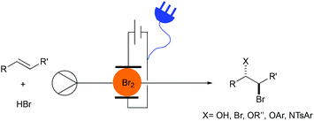
Herein we describe the electrochemical bromination of activated and unactivated alkenes in a flow reactor under single-pass conditions (Fig. 1). These transformations include dibrominations, bromohydroxylations and bromoalkoxylations.
Results and discussion
The reaction conditions for the dibromination of alkenes were adapted from a batch electrochemical procedure from Lei and co-workers.28 Flow experiments were carried out using an Ion Electrochemical Reactor from Vapourtec Ltd equipped with a platinum foil cathode and graphite anode.38 The electrodes were separated by a 500 μm FEP spacer to provide a channel resulting in a reactor volume of 600 μL and an exposed surface area of 12 mA cm−2 for each electrode. The bromination of styrene (1a) was targeted in an effort to develop optimal electrochemical conditions (Table 1). Applying a flow rate of 0.1 mL min−1, an applied current of 48 mA, a styrene concentration of 100 mM and charge of 3.0 F mol−1 gave the dibromide 2a as the main product in 54% yield and the bromohydrin 3a in 17% yield (Table 1, entry 1). In contrast to the batch experiment,28 no additional water was needed and any additional supporting electrolyte could be omitted due to the significantly smaller interelectrode gap. An increase in the concentration of HBr from 200 mM to 400 mM and 600 mM led to an increase in 2a to 74% and 80% yield, respectively (Table 1, entries 2 and 3). Pleasingly, a decrease of the bromohydrin side product could be observed. The concentration of 600 mM of hydrobromic acid was used for the subsequent experiments. Changing the graphite anode material to glassy carbon gave the product 2a in 73% yield while a platinum foil anode resulted in 79% yield (Table 1, entries 4 and 5). Meanwhile, increasing the applied charge resulted in 92% (3.5 F mol−1), 86% (4 F mol−1) and 80% (4.5 F mol−1) yield (Table 1, entries 6–8). Increased flow rates at 4 F mol−1, and thereby higher charge densities, led to a slight decrease in the yield (Table 1, entries 9 and 10).| Entry | HBr [mM] | Charge [F mol−1] (current) | Flow rate [mL min−1] | Yield 2a![[thin space (1/6-em)]](https://www.rsc.org/images/entities/char_2009.gif) a [%] a [%] |
Yield 3a![[thin space (1/6-em)]](https://www.rsc.org/images/entities/char_2009.gif) a [%] a [%] |
|---|---|---|---|---|---|
| Reaction conditions: styrene (0.1 M), hydrobromic acid (48% w/w in water); acetonitrile (MeCN); constant current; undivided cell; graphite anode (surface area: 12 cm2); Pt foil cathode; amount of water (HBr [mM]): 2% (200), 5% (400), 7% (600 mM).a Yields are determined by NMR with 1,3,5-trimethoxybenzene as internal standard.b Glassy carbon anode.c Pt foil anode.d Pt coated Ti cathode.e Isolated yield, 3a not isolated. | |||||
| 1 | 200 | 3 (48 mA) | 0.1 | 54 | 17 |
| 2 | 400 | 3 (48 mA) | 0.1 | 74 | 6 |
| 3 | 600 | 3 (48 mA) | 0.1 | 80 | 3 |
| 4b | 600 | 3 (48 mA) | 0.1 | 73 | 17 |
| 5c | 600 | 3 (48 mA) | 0.1 | 79 | 13 |
| 6 | 600 | 3.5 (56 mA) | 0.1 | 92 | 4 |
| 7 | 600 | 4 (64 mA) | 0.1 | 86 | 3 |
| 8 | 600 | 4.5 (72 mA) | 0.1 | 80 | 4 |
| 9 | 600 | 4 (129 mA) | 0.2 | 78 | 8 |
| 10 | 600 | 4 (257 mA) | 0.4 | 79 | 9 |
| 11d | 600 | 4 (257 mA) | 0.4 | 86e | |
By using a platinum coated titanium cathode and a graphite anode, 1,2-dibromo-1-phenylethane (2a) could be obtained in an 86% isolated yield under the optimized conditions of 100 mM styrene and 600 mM hydrobromic acid in acetonitrile, a flow rate of 0.4 mL min−1 and a charge of 4 F mol−1 (applied current: 257 mA) resulting in a productivity of 545 mg h−1 (Table 1, entry 11).
In order to demonstrate the scalability of the protocol, the optimized conditions were applied for 9.5 hours to afforded 3.93 g of product 2a, which corresponds to a yield of 65% and a productivity of 413 mg h−1. Alkene and hydrobromic acid were mixed from two separate reservoirs before entering the reactor. When premixing the reaction mixture for a 9 hours experiment, the desired product 2a was obtained with a significantly reduced yield of 47%. A control experiment confirmed a competing side reaction in the syringe, which led to the formation of 1-phenylethanol in the reservoir upon a prolonged reaction time.
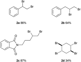
The reaction with allyl benzene gave 64% yield of 1,2-dibromo-3-phenylpropane (2b) (Fig. 2). 2-(Pent-4-en-1-yl)isoindoline-1,3-dione was converted to 2c in 84% yield. The reaction with 1,4-cyclohexadiene afforded the tetrabrominated product (2d) in 34% yield while the dibromination product was observed in trace amounts.
Following this, the optimization for the electrochemical bromohydrin formation in flow was targeted. The concentration of water, hydrobromic acid and styrene were considered as well as the electrode materials, charge density and flow rate. The initial conditions consisted of 100 mM styrene and 200 mM hydrobromic acid, a flow rate of 0.2 mL min−1 and 3 F mol−1 (97 mA) charge. At a water concentration of 5% in acetonitrile, the selectivity of the reaction could be switched and the bromohydrin was observed in 40% yield, while the dibromide was obtained in 29% yield (Table 2, entry 1). By increasing the water concentration, the formation of the dibromide was further suppressed while the yield of bromohydrin 3a peaked at 79% with a water concentration of 20% (Table 2, entry 2).
| Entry | H2O added[%] | HBr [mM] | Charge [F mol−1] | Flow rate [mL min−1] | Yield 2a![[thin space (1/6-em)]](https://www.rsc.org/images/entities/char_2009.gif) a [%] a [%] |
Yield 3a![[thin space (1/6-em)]](https://www.rsc.org/images/entities/char_2009.gif) a [%] a [%] |
|---|---|---|---|---|---|---|
| Reaction conditions: styrene (100 mM), hydrobromic acid (48% w/w in water); additional H2O/MeCN; constant current; undivided cell; Pt foil cathode, graphite anode (surface area: 12 cm2).a Yields are determined by NMR with 1,3,5-trimethoxybenzene as internal standard. | ||||||
| 1 | 5 | 200 | 3 (97 mA) | 0.2 | 29 | 40 |
| 2 | 20 | 200 | 3 (97 mA) | 0.2 | 14 | 79 |
| 3 | 30 | 200 | 3 (97 mA) | 0.2 | 7 | 81 |
| 4 | 20 | 100 | 3 (97 mA) | 0.2 | 1 | 31 |
| 5 | 20 | 180 | 3 (97 mA) | 0.2 | 9 | 85 |
| 6 | 30 | 180 | 3 (97 mA) | 0.2 | 8 | 85 |
| 7 | 30 | 180 | 2 (64 mA) | 0.2 | 9 | 63 |
| 8 | 30 | 180 | 4 (129 mA) | 0.2 | 4 | 86 |
| 9 | 30 | 180 | 5 (161 mA) | 0.2 | 3 | 68 |
| 10 | 30 | 180 | 3 (193 mA) | 0.4 | 7 | 81 |
| 11 | 30 | 180 | 4 (257 mA) | 0.4 | 6 | 75 |
| 12 | 30 | 180 | 3 (290 mA) | 0.6 | 6 | 72 |
| 13 | 30 | 180 | 4 (386 mA) | 0.6 | 6 | 70 |
In the next optimization step, the influence of the hydrobromic acid concentration was investigated. The lowest concentration of 100 mM suppressed the dibromide formation to trace amounts, but the yield for bromohydrin was significantly decreased to 31% (Table 2, entry 4). The optimal concentration of hydrobromic acid was identified at 180 mM which resulted in a yield of 85% of the bromohydrin and 9% of the dibromide (Table 2, entries 5 and 6).
Next, different electrode materials were tested. Exchanging a graphite anode to materials such as Panasonic carbon (67%), glassy carbon (72%) or platinum foil (2%) had a negative effect on the bromohydrin formation. Also, varying the cathode material did not impact the yield significantly: platinum coated on titanium (85%), nickel (75%), graphite (82%) (see ESI, Table S3†).
Optimization of the applied charge had a positive influence on the yield. For instance, a yield of 86% for the bromohydrin was observed with an increased charge of 4 F mol−1 at a flow rate of 0.2 mL min−1 (Table 2, entry 8). Further increases (5 F mol−1) or decreases (2 F mol−1) of the charge decreased the yield to 68% and 63%, respectively (Table 2, entries 7 and 9). Increasing the flow rate to 0.4 mL min−1 or 0.6 mL min−1 resulted in decreased yields of 75% and 70%, respectively (Table 2, entries 11 and 13). Interestingly, a simultaneous decrease of current to 3 F mol−1 at 0.4 mL min−1 still afforded 81% of bromohydrin (Table 2, entry 10).
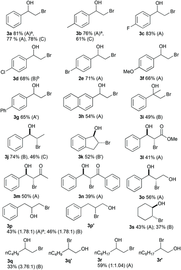
To demonstrate the versatility of the optimised reaction conditions, several aromatic and aliphatic alkenes were converted to the corresponding bromohydrins (Fig. 3). Since doubling the flow rate from the optimal conditions (Table 2, entries 8 and 10) did not significantly drop the yield, both conditions were investigated in an effort to maximize the productivity of the system (conditions A and B). The reaction with styrene and styrene derivatives afforded the bromohydrins 3a–f in good to excellent yields. Due to insolubility, 4-vinylbiphenyl (80 mM) was reacted in a solvent mixture of H2O/MeCN/THF (3![[thin space (1/6-em)]](https://www.rsc.org/images/entities/char_2009.gif) :
:![[thin space (1/6-em)]](https://www.rsc.org/images/entities/char_2009.gif) 3
3![[thin space (1/6-em)]](https://www.rsc.org/images/entities/char_2009.gif) :
:![[thin space (1/6-em)]](https://www.rsc.org/images/entities/char_2009.gif) 4). The current and hydrobromic acid concentration were kept at 129 mA and 180 mM and 3g was obtained in a good yield of 65%. The reaction with 2-vinylnaphthalene resulted in 54% yield of 3h. The conversion of methyl cinnamate furnished 3l in a moderate yield. Two α,β-unsaturated ketones were converted in moderate yields to 3m and 3n. The reaction with allylbenzene gave mixtures of regioisomers 3p and 3p′ (1.78
4). The current and hydrobromic acid concentration were kept at 129 mA and 180 mM and 3g was obtained in a good yield of 65%. The reaction with 2-vinylnaphthalene resulted in 54% yield of 3h. The conversion of methyl cinnamate furnished 3l in a moderate yield. Two α,β-unsaturated ketones were converted in moderate yields to 3m and 3n. The reaction with allylbenzene gave mixtures of regioisomers 3p and 3p′ (1.78![[thin space (1/6-em)]](https://www.rsc.org/images/entities/char_2009.gif) :
:![[thin space (1/6-em)]](https://www.rsc.org/images/entities/char_2009.gif) 1) in 43% (method A) or 46% (method B) yield. The unactivated alkenes 1-hexene and 1-decene resulted in 33% yield with a 3.76
1) in 43% (method A) or 46% (method B) yield. The unactivated alkenes 1-hexene and 1-decene resulted in 33% yield with a 3.76![[thin space (1/6-em)]](https://www.rsc.org/images/entities/char_2009.gif) :
:![[thin space (1/6-em)]](https://www.rsc.org/images/entities/char_2009.gif) 1 ratio of regioisomers (3q/3q′) and 59% yield with a 1
1 ratio of regioisomers (3q/3q′) and 59% yield with a 1![[thin space (1/6-em)]](https://www.rsc.org/images/entities/char_2009.gif) :
:![[thin space (1/6-em)]](https://www.rsc.org/images/entities/char_2009.gif) 1.04 ratio of regioisomers (3r/3r′). The unsymmetrical internal alkene trans-2-hexene did not afford the bromohydrin. The bromohydrin 3s was obtained in moderate yields from cyclohexene with method A and B. The use of graphite as a cathode material gave 3a in 78% yield but for 3b and 3j yields dropped significantly compared to methods utilizing platinum cathodes.
1.04 ratio of regioisomers (3r/3r′). The unsymmetrical internal alkene trans-2-hexene did not afford the bromohydrin. The bromohydrin 3s was obtained in moderate yields from cyclohexene with method A and B. The use of graphite as a cathode material gave 3a in 78% yield but for 3b and 3j yields dropped significantly compared to methods utilizing platinum cathodes.
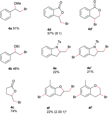
Alcohols could be used as nucleophiles to trap the bromonium species, and internal nucleophiles would provide cyclized reaction products (Fig. 4). By changing from water to 30% of alcohol in acetonitrile, the bromoalkoxylated products were obtained. The reaction of styrene with 150 mM hydrobromic acid gave the corresponding methoxylated and ethoxylated products 4a and 4b in moderate yields at 0.4 mL min−1 and 4 F mol−1. Alkenes containing internal nucleophiles were used with conditions adapted from method A. The substrates were electrolyzed in acetonitrile with 180 mM hydrobromic acid at a flow rate of 0.2 mL min−1 and charge of 4 F mol−1. 4-Pentenoic acid was converted with a water concentration of 5% in acetonitrile to the corresponding lactone 4c in 74% yield. The reaction of 2-vinyl benzoic acid with 30% water in acetonitrile proceeded with a yield of 57% (0.4 mL min−1, 3 F mol−1) to afford an inseparable mixture of regioisomers. The 5-membered ring was obtained as the major isomer 4d and the 6-membered ring as the minor one 4d′ in a ratio of 9![[thin space (1/6-em)]](https://www.rsc.org/images/entities/char_2009.gif) :
:![[thin space (1/6-em)]](https://www.rsc.org/images/entities/char_2009.gif) 1. The reaction with N-(2-allylphenyl)-4-methylbenzenesulfonamide led to cyclization as well as subsequent bromination of the aromatic ring. The cyclized product 4e was afforded in 22% yield. Cyclization and bromination of the aromatic ring gave product 4e′ in 21% yield. The electrochemical brominaton of 2-allyl-6-methylphenol led to the bromination of the aromatic ring and the formation of 5- and 6-membered rings with the phenolic oxygen acting as nucleophile. The resulting complex mixture of products did not allow a conclusion about the selectivity of the reaction from the crude NMR spectrum. A mixture of regioisomers 4f and 4f′ could be isolated in a ratio of 2.33
1. The reaction with N-(2-allylphenyl)-4-methylbenzenesulfonamide led to cyclization as well as subsequent bromination of the aromatic ring. The cyclized product 4e was afforded in 22% yield. Cyclization and bromination of the aromatic ring gave product 4e′ in 21% yield. The electrochemical brominaton of 2-allyl-6-methylphenol led to the bromination of the aromatic ring and the formation of 5- and 6-membered rings with the phenolic oxygen acting as nucleophile. The resulting complex mixture of products did not allow a conclusion about the selectivity of the reaction from the crude NMR spectrum. A mixture of regioisomers 4f and 4f′ could be isolated in a ratio of 2.33![[thin space (1/6-em)]](https://www.rsc.org/images/entities/char_2009.gif) :
:![[thin space (1/6-em)]](https://www.rsc.org/images/entities/char_2009.gif) 1 in 22% yield. Due to the challenging purification process, a conclusion on the regioselectivity of the reaction cannot be drawn.
1 in 22% yield. Due to the challenging purification process, a conclusion on the regioselectivity of the reaction cannot be drawn.
Conclusions
In this work we provide a flow set-up to conduct various electrochemical brominations of alkenes by using hydrobromic acid as bromine source. The outcome of the reaction was easily controlled by switching the cosolvent. Bromohydrins, dibromides and vicinal bromo ethers were electrochemically synthesized in flow with moderate to excellent yields. The use of chemical oxidants, which are commonly used in bromination reactions, is completely avoided leading to a substantial reduction of waste. The flow set-up facilitated a safe handling of the intermediary generated bromine. The described methods have the potential of facile up-scaling. Furthermore, internal nucleophiles such as carboxylic acids, N-tosylaniline and phenol led to cyclized products.Conflicts of interest
There are no conflicts to declare.Acknowledgements
Financial support from the School of Chemistry, Cardiff University, UK, is highly appreciated. We like to thank B. Winterson for helpful discussions.References
- M. Eissen and D. Lenoir, Chem. – Eur. J., 2008, 14, 9830–9841 CrossRef CAS PubMed.
- I. Saikia, A. J. Borah and P. Phukan, Chem. Rev., 2016, 116, 6837–7042 CrossRef CAS PubMed.
- M. R. Scheide, C. R. Nicoleti, G. M. Martins and A. L. Braga, Org. Biomol. Chem., 2021, 19, 2578–2602 RSC.
- S. Arai, T. Takeuchi, M. Ishikawa, T. Takeuchi, M. Yamazaki and M. Hida, J. Chem. Soc., Perkin Trans. 1, 1987, 481–487 RSC.
- K. C. Nicolaou, T. Caulfield, H. Kataoka and T. Kumazawa, J. Am. Chem. Soc., 1988, 110, 7910–7912 CrossRef CAS.
- H. Kawashima and Y. Kobayashi, Org. Lett., 2014, 16, 2598–2601 CrossRef CAS PubMed.
- J. Xu and S. Xu, Synthesis, 2004, 276–282 CrossRef CAS.
- E. Espinosa, C. Belmant, F. Pont, B. Luciani, R. Poupot, F. Romagne, H. Brailly, M. Bonneville and J. Fournie, J. Biol. Chem., 2001, 276, 18337–18344 CrossRef CAS PubMed.
- J. Read and W. G. Reid, J. Chem. Soc., 1928, 1487–1493 RSC.
- J. Zablcky and M. Nutkovltch, Ind. Eng. Chem. Prod. Res. Dev., 1986, 25, 372–375 CrossRef.
- C. O. Guss and R. Rosenthal, J. Am. Chem. Soc., 1955, 77, 2549–2549 CrossRef CAS.
- D. R. Dalton, V. P. Dutta and D. C. Jones, J. Am. Chem. Soc., 1968, 90, 5498–5501 CrossRef CAS.
- D. R. Dalton and V. P. Dutta, J. Chem. Soc. B, 1971, 85–89 RSC.
- F. Huet, A. Lechevallier and J. M. Conia, Tetrahedron Lett., 1981, 22, 3585–3588 CrossRef CAS.
- H. Masuda, K. Takase, M. Nishio, A. Hasegawa, Y. Nishiyama and Y. Ishii, J. Org. Chem., 1994, 59, 5550–5555 CrossRef CAS.
- J. S. Yadav, B. V. S. Reddy, G. Baishya, S. J. Harshavardhan, C. J. Chary and M. K. Gupta, Tetrahedron Lett., 2005, 46, 3569–3572 CrossRef CAS.
- L. S. de Almeida, P. M. Esteves and M. C. S. de Mattos, Synlett, 2007, 1687–1690 CAS.
- S. Song, X. Huang, Y. F. Liang, C. Tang, X. Li and N. Jiao, Green Chem., 2015, 17, 2727–2731 RSC.
- Q. Jiang, Y. Liang, Y. Zhang and X. Zhao, Org. Lett., 2020, 22, 7581–7587 CrossRef CAS PubMed.
- S. Torii, K. Uneyama and K. Ueda, J. Org. Chem., 1984, 49, 1830–1832 CrossRef CAS.
- S. Torii, Y. Kubo, Y. Miyawaki and H. Tanaka, in Reactive Intermediates in Organic and Biological Electrochemistry, ed. D. G. Peters, H. J. Schäfer, M. S. Workentin and J. Yoshida, The Electrochemical Society, 2001, pp. 29–32 Search PubMed.
- S. Torii, K. Uneyama, H. Tanaka, T. Yamanaka, T. Yasuda, M. Ono and Y. Kohmoto, J. Org. Chem., 1981, 46, 3312–3315 CrossRef CAS.
- K. Uneyama, Y. Masatsugu and S. Torii, Bull. Chem. Soc. Jpn., 1985, 58, 2361–2365 CrossRef CAS.
- Y. Ashikari, A. Shimizu, T. Nokami, J. I. Yoshida and S. S, J. Am. Chem. Soc., 2013, 135, 16070–16073 CrossRef CAS PubMed.
- A. Shimizu, R. Hayashi, Y. Ashikari, T. Nokami and J. I. Yoshida, Beilstein J. Org. Chem., 2015, 11, 242–248 CrossRef PubMed.
- O. V. Bityukov, V. A. Vil’, G. I. Nikishin and A. O. Terent'ev, Adv. Synth. Catal., 2021, 363, 3070–3078 CrossRef CAS.
- M. N. Élinson, I. v. Makhova and G. I. Nikishin, Bull. Acad. Sci. USSR, 1988, 37, 1636–1641 CrossRef.
- Y. Yuan, A. Yao, Y. Zheng, M. Gao, Z. Zhou, J. Qiao, J. Hu, B. Ye, J. Zhao, H. Wen and A. Lei, iScience, 2019, 12, 293–303 CrossRef CAS PubMed.
- K. Kulangiappar, M. Ramaprakash, D. Vasudevan and T. Raju, Synth. Commun., 2016, 46, 145–153 CrossRef CAS.
- K. Kulangiappar, G. Karthik and M. A. Kulandainathan, Synth. Commun., 2009, 39, 2304–2309 CrossRef CAS.
- A. G. Hilt, J. Strehl, M. L. Abraham, J. Strehl and M. L. Abraham, Angew. Chem., 2021, 60, 9996–10000 CrossRef PubMed.
- A. P. Kale, P. Nikolaienko, K. Smirnova and M. Rueping, Eur. J. Org. Chem., 2021, 3496–3500 CrossRef.
- K. Watts, A. Baker and T. Wirth, J. Flow Chem., 2014, 4, 2–11 CrossRef.
- A. A. Folgueiras-Amador and T. Wirth, in Science of Synthesis, Flow Chemistry in Organic Synthesis, ed. T. F. Jamison and G. Koch, Thieme Verlag, Stuttgart, 2018 Search PubMed.
- N. Tanbouza, T. Ollevier and K. Lam, iScience, 2020, 23, 101720 CrossRef CAS PubMed.
- Z. Tan, Y. Liu, R. Helmy, N. R. Rivera, D. Hesk, S. Tyagarajan, L. Yang and J. Su, Tetrahedron Lett., 2017, 58, 3014–3018 CrossRef CAS.
- D. Vasudevan and C. A. Basha, Bull. Electrochem., 2000, 16, 341–344 CAS.
- Ion electrochemical reactor, https://www.vapourtec.com/products/flow-reactors/ion-electrochemical-reactor-features/, (accessed July 2021).
Footnote |
| † Electronic supplementary information (ESI) available. See DOI: 10.1039/d1ob01302e |
| This journal is © The Royal Society of Chemistry 2021 |


