Electro-oxidation of alcohols over electrochemically activated nickel alloys for energy-saving hydrogen production†
Ming
Ni
a,
Minyuan
Tan
b,
Kang
Luo
c,
Daochuan
Jiang
 a,
Yupeng
Yuan
 a,
Chuhong
Zhu
 *a,
Haiwei
Du
 *a and
Hangjuan
Ren
*d
aSchool of Materials Science and Engineering, Anhui University, Hefei 230601, China. E-mail: chzhu@ahu.edu.cn; haiwei.du@ahu.edu.cn
bNational Synchrotron Radiation Laboratory, School of Nuclear Science and Technology, University of Science and Technology of China, Hefei 230029, China
cShanghai Leading Technology Co. Ltd, Shanghai 201807, China
dSchool of Chemistry, Monash University, Clayton, Victoria 3800, Australia. E-mail: hangjuan.ren@monash.edu
First published on 6th August 2024
Abstract
Water electrolysis has been considered as a green and sustainable technique for hydrogen production, while the sluggish kinetics of the oxygen evolution reaction (OER) and the insufficient active sites remain bottlenecks for practical performance. Herein, we present in situ electrochemical activation of nickel (Ni) alloys for water splitting assisted by the electro-oxidation of organic molecules. It has been discovered that in situ electrochemical activation results in an increased degree of metal oxidation, thereby inducing more high-valence active metal species (NiOOH). These species not only function as active sites for surface adsorption but also facilitate electron transfer. Subsequently, two representative organic molecules, methanol and ethanol, are introduced to further promote the water electrolysis. Through a combination of electrochemical testing and in situ Raman spectroscopy, it has been revealed that the activated Ni alloy demonstrates a stronger response to the adsorbed alcohol molecules and tends to form β-NiOOH at lower potentials compared to the pristine one, resulting in enhanced water splitting. The present work advances a simple activation method for transition metal-based electrocatalysts for highly efficient alcohol oxidation-assisted water electrolysis.
Introduction
Hydrogen, as a carbon-free and renewable energy, holds promise as a viable alternative to traditional fossil fuels in the foreseeable future. Compared to conventional hydrogen production techniques, water electrolysis emerges as a cleaner and more sustainable pathway. However, the electroproduction of hydrogen at the cathode is hindered by the sluggish kinetics of water oxidation at the anode. Therefore, many efforts have been made to improve water oxidation.Research on water oxidation has continued to evolve, marked by three main stages of progress: (i) exploration of highly efficient electrocatalysts to enhance the activity of the oxygen evolution reaction (OER), (ii) utilization of sacrificial agents' oxidation at the anode, and (iii) electrosynthesis at the anode.1 An increasing number of researchers are gravitating towards and exploring the third stage, as this method accelerates hydrogen production at cathodes while simultaneously introducing an innovative pathway for converting low-cost industrial feedstocks into high-value chemicals.2,3 In these methods, organic molecules with theoretical oxidation potentials lower than that of water, thereby suggesting greater ease of electro-oxidation, are added into the anolyte. The range of organic molecules is extensive, including but not limited to alcohol and aldehyde molecules, which are typically converted to derivative aldehydes or acids.4 Moreover, the electro-oxidation of biomass, including compounds like 5-hydroxymethylfurfural and glycerol, further underscores the potential of electrosynthesis in harnessing renewable resources.5,6 This method allows the activation and subsequent functionalization of C–H bonds, rendering the transformation of hydrocarbons into highly reactive intermediates more achievable, thus demonstrating its versatility across diverse chemical structures.7
To optimally employ electrosynthesis in water electrolysis, a key consideration lies in the selection and utilization of electrocatalysts. Transition metals, such as nickel (Ni), cobalt (Co), and iron (Fe), present themselves as compelling options among non-noble metals for the development of multi-component or even high-entropy electrocatalysts.8,9 When these catalysts are used in water electrolysis, the phenomenon of an increased degree of metal oxidation commonly occurs, and thereby the actual catalytic properties of the surfaces are closely related to the presence of ‘metal oxidation’.10 Hence, researchers aim to generate metal oxidation with higher activity to enhance electrolytic performance. Various methods have been employed for this purpose. For example, surface activity discrepancies arise through the manipulation of the initial atomic Ni/Fe ratio in the catalyst, thereby regulating the formation and composition of Ni/Fe oxo-hydroxide.11 The activity of metal oxidation can also be modulated by defect engineering,12 heterostructure construction,13 partial dissolution,10etc.
In the present work, metal oxidation was regulated through in situ electrochemical activation of nickel alloys under cyclic voltammetry (CV). After electrochemical activation, high-valence nickel oxyhydroxides are formed in situ, acting as active sites for surface adsorption and facilitating electron transfer. The addition of alcohols (methanol and ethanol) to the anolyte enhances water electrolysis while simultaneously facilitating the electrosynthesis of acids. Moreover, activated Ni alloys demonstrate excellent stability, exceeding 144 hours for the alcohol oxidation reaction (AOR) at 100 mA cm−2 with no apparent decline in potential. Further in situ Raman spectroscopy reveals that the activated Ni alloy exhibited enhanced adsorption of alcohol molecules and inclined towards producing β-NiOOH at lower potentials in contrast to the pristine Ni alloy.
Experimental procedure
Materials and chemicals
Ingots were purchased from Jiangyin Meiyuan Stainless Steel Co. Ltd., China. Methanol (MeOH, Mw: 32.04) and potassium hydroxide (KOH, Mw: 56.11) were purchased from Shanghai Aladdin Biochemical Technology Co., Ltd. and Sinopharm Chemical Reagent Co. Ltd., respectively.Preparation of Ni alloys
First, the ingot was remelted using a vacuum induction furnace at 1450 °C. Through forging, hot rolling and cold rolling, the alloy was thermally treated in a batch-type furnace at 1080 °C for 10 min. Following rapid air cooling for 30 min, the cold-rolled belt was annealed at 900 °C for 60 min. Finally, the alloy was cut into small pieces measuring 1 × 3 cm2 in size and 0.2 mm in thickness (Fig. S1†) for further electrochemical activation.Electrochemical activation of Ni alloys
Electrochemical activation was performed using an electrochemical workstation (CHI660E, Chenhua, Shanghai) with a standard three-electrode cell, employing the Ni alloy as the working electrode, Ag/AgCl (containing saturated KCl) as the reference electrode, and graphite rod as the counter electrode. The nickel alloy (1 × 3 cm2 in size) was introduced into a 1 M KOH electrolyte, with a specific immersion area of 1 cm2. Following this, electrochemical activation was performed via cyclic voltammetry (CV) across a potential range from 1.1 to 1.6 V vs. reverse hydrogen electrode (RHE) potential at a scan rate of 50 mV s−1 for 50, 100, or 200 cycles. The degree of activation varies depending on the number of cycles employed. Activated Ni alloys in this paper refer specifically to samples that have undergone 200 cycles of treatment. In addition, normal pulse voltammetry (NPV, see details in the ESI†) was performed using a multi-channel potentiostat (VMP3, Bio-Logic). The applied potential was calibrated to the RHE potential according to the Nernst equation: E(RHE) = E(Ag/AgCl) + 0.197 V + 0.059 × pH.Electrocatalytic tests
During the electrocatalytic tests, a 1 M KOH electrolyte was employed, with variations in methanol concentrations. To evaluate the electrocatalytic performance before and after activation, linear sweep voltammetry (LSV) was carried out at a scan rate of 5 mV s−1 with 90% iR compensation. The long-term stability test was performed by maintaining a current density of 100 mA cm−2 using chronopotentiometry measurements. Additionally, electrochemical impedance spectra (EIS) were recorded across a frequency range from 0.01 to 106 Hz.Materials characterization
A thorough analysis of elemental compositions, crystal structure, surface morphology, and valence states was conducted using a suite of advanced analytical techniques: inductively coupled plasma optical emission spectroscopy (ICP-OES, Agilent 5110), X-ray diffraction (XRD, Rigaku SmartLab 9 kW), scanning electron microscopy (SEM, Hitachi S-4800), atomic force microscopy (AFM, Bruker Dimension Icon) and X-ray photoelectron spectroscopy (XPS, ESCALAB 250Xi). Further microstructural analysis and elemental distribution mapping were performed using aberration-corrected transmission electron microscopy (ACTEM, Titan Themis Z), following sample preparation via a focused ion beam (FIB, ZEISS Crossbeam 550). Surface wettability was assessed through water contact angle measurements using a drop shape analyzer (DSA30S). The oxidation products from the anode were analyzed using high-performance liquid chromatography (HPLC, Waters Alliance e2695 HPLC system). Prior to analyses, 1 mL of electrolyte was diluted with 1 mL of 0.5 M H2SO4 and extracted using 2 mL of CHCl2.Results and discussion
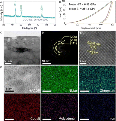
The phase structure, mechanical performance and microstructure of the as-prepared Ni alloy were investigated prior to the electrochemical activation. As shown in the XRD pattern (Fig. 1A), the diffraction peaks corresponding to the (111), (200) and (220) planes are well matched with the standard card of face-centered cubic nickel (COD 96-900-0090). Furthermore, all diffraction peaks exhibit negative shifts, indicating lattice distortion due to elemental alloying within the Ni lattice structure. Compared to Ni, all the dopants including Cr, Co, Mo, and Fe exhibit a larger atomic radius.14 According to Bragg's law, introducing these dopants into the lattice structure induces lattice expansion, resulting in a negative shift of the diffraction peak positions. Fig. 1B shows the nanoindentation load–displacement curves, which are measured up to a maximum load of Pmax = 100 mN. The mean values of hardness and elastic modulus of the Ni alloy are 6.92 GPa and 251.1 GPa (Table S1†), respectively, demonstrating excellent mechanical properties comparable to those reported for Ni alloys.15 To reveal the microstructural information, the Ni foil underwent FIB processing and was observed using a TEM. In Fig. 1C and S2,† the as-prepared Ni alloy shows a dense structure consisting of clearly defined grains. In the selected area electron diffraction (SAED) pattern (Fig. 1D), diffraction rings corresponding to the Ni alloy are observed, which are consistent with XRD analysis. Upon further magnification, lattice fringes with an interplanar spacing of 0.228 nm are assigned to the (111) plane of the Ni alloy (Fig. 1E).In addition, elemental compositions were studied by ICP-OES and TEM energy dispersive X-ray spectroscopy (EDX). As shown in Tables S2 and S3,† the as-obtained Ni alloy contains five primary elements, including Ni, Cr, Co, Mo, and Fe, which are uniformly distributed within the Ni alloy, as confirmed by the TEM elemental mapping results (Fig. 1F).
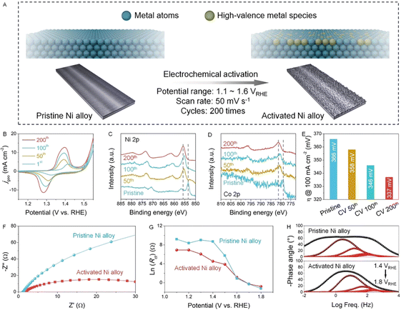
Next, the Ni alloy undergoes electrochemical activation through cyclic voltammetry (CV) for a varying number of cycles, as demonstrated in Fig. 2B. No apparent changes in the elemental compositions are observed after activation, as supported by the ICP-OES results in Table S2.† However, significant alterations in the surface redox properties of the Ni alloys are evident from the oxidation peak around ∼1.4 VRHE, attributed to the Ni2+/Ni3+ oxidation (Fig. 2B).16 The current densities at redox peaks increase gradually with increasing activation cycles, and the integrated area also reflects the number of electrochemically active sites (Fig. S3†).17 Since the electrochemical activation does not alter the crystal structure of the Ni alloy (Fig. S4†), we turned to use the XPS technique to determine changes of surface metal elements. Both XPS Ni 2p and Co 2p spectra show a peak shift towards higher binding energies, indicating an increased degree of metal oxidation (Fig. 2C and D).18 It is accepted that the XPS technique is usually used to detect the element signals at the surface.19 After the electrochemical activation, a peak shift towards higher binding energies in XPS spectra is distinct. Since the crystal structure maintains the bulk phase (Fig. S4†) and the metal dissolution into the electrolyte is not detected (Fig. S5 and Table S4†), we believe that the electrochemical activation in this work can only affect the surface elements and therefore the peak shift in the XPS spectra is a direct result of the surface metal oxidation induced by electrochemical activation. Moreover, the surface area of the activated Ni alloy did not exhibit a significant change (Fig. S6†), indicating that the enhancement in electrochemical performance is not due to an increase in the Ni alloy surface area. Such oxidation of the surface metal sites, inducing a transition to the catalytically active state, is acknowledged to promote the electrocatalytic reaction.20
Furthermore, electrochemical analyses were conducted to assess the properties of both pristine and activated Ni alloys in a KOH catholyte. The OER performance was evaluated by recording the LSV curves. Notably, the overpotential at a current density of 100 mA cm−2 decreases from 366 mV for the pristine Ni alloy to 337 mV for the activated Ni alloy (Fig. 2E and S7†). This reduction in overpotential indicates an enhancement in electrocatalytic activity, as corroborated by the decrease in Tafel slopes (Fig. S8†), indicating that the electrochemical activation effectively accelerates the OER reaction kinetics. Additionally, the electrochemical surface area (ECSA) normalized LSV curves were plotted after performing the CV tests within the non-faradaic potential window,21 further confirming the intrinsic activity enhancement via electrochemical activation (Fig. S9†). Moreover, the reaction kinetics and charge transport behavior were investigated by potential-dependent EIS (Fig. S10†).22 The Nyquist plots of the Ni alloy after electrochemical activation (Fig. 2F) demonstrate a smaller semicircle radius compared to the pristine Ni alloy, indicating reduced charge transfer resistance (Rct). Furthermore, fitting the Nyquist plots with the equivalent circuit model (Fig. S11†) allows for determination of Rct, Rads (resistance of interfacial adsorption), and Cads (capacitance of interfacial adsorption), enhancing insights into the charge transfer kinetics (Table S5†). Compared to the pristine Ni alloy, the activated Ni alloy exhibits a smaller Rct, a lower peak of the phase angle at low frequencies, and a faster drop of the phase angle with increasing potentials (Fig. 2G and H). After electrochemical activation, the generated high-valence NiOOH species at the surface effectively promote the adsorption of water molecules, and therefore facilitate the electron transfer since the electrode–electrolyte contact resistance becomes smaller owing to a hydrophilic catalyst surface. This indicates that the activated Ni alloy has a faster charge transfer and ion diffusion capacity at the catalyst/electrolyte interface, thus contributing to the surface intermediate interaction.23–25 Furthermore, the pristine and activated Ni alloys were also subjected to the HER test, and the activity of the activated one is still better than that of the pristine counterpart (Fig. S12†). In summary, the comprehensive electrochemical characterization confirms that the electrochemical activation enhances the Ni alloy's OER performance by accelerating reaction kinetics, thereby making it comparable to the most effective electrocatalysts reported previously (Table S6†).
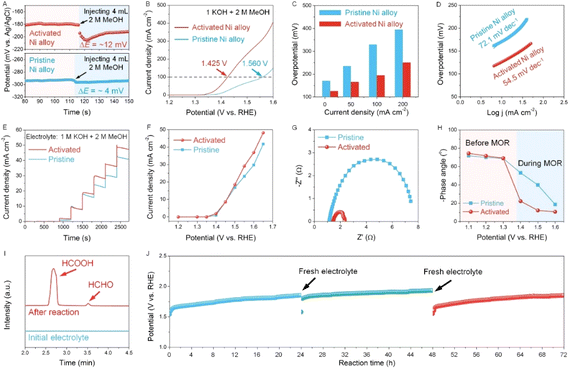
Now we evaluate the promoting effect of electro-oxidation of alcohols on hydrogen production. As a representative, MeOH with different concentrations is added into the electrochemical cell, and the concentration of 2 M is selected in spite of the concentration-dependent current density due to a relatively higher concentration (Fig. S13†). We then directly assess the reaction kinetics and charge transport from the viewpoint of the electrode/electrolyte interface.26 First, the potential change in OCP is used to reflect the response and sensitivity of both pristine and activated Ni alloy towards the methanol molecule. As seen in the OCP plots, the activated Ni alloy is more sensitive to MeOH as the change in OCP for the activated Ni alloy is more distinct than that of the pristine Ni alloy when injecting 2 M MeOH (Fig. 3A). This potential change when reaching the electrode potential equilibrium is related to the adsorbates in the Helmholtz layer, reflecting an enhanced adsorption of MeOH.27 Afterwards, the LSV curves of the pristine and activated Ni alloys were collected in the presence of 2 M MeOH. It is clearly seen that the LSV curves of the activated Ni alloy negatively shift and the overpotential significantly decreases compared to the neat one (Fig. 3B and C). The corresponding Tafel slope also shows a decrease from 72.1 mV dec−1 for the pristine Ni alloy to 54.5 mV dec−1 for the activated Ni alloy (Fig. 3D). This fast reaction kinetics is probably attributed to the enhanced surface response to MeOH at the activated electrode surface after in situ electrochemical activation, as supported by a lower contact angle (Fig. S14†). To confirm this, the normal pulse voltammetry (NPV) technique was applied (Fig. 3E and see details in Fig. S15†), and the steady-state current densities at different potentials can be derived accordingly (Fig. 3F). At lower potentials (1.2–1.5 VRHE), the current densities of both the pristine and activated Ni alloys show a very slight change since the methanol oxidation reaction (MOR) is not distinct. When the potential is above 1.5 VRHE, the current density of the activated Ni alloy is higher than that of the pristine Ni alloy, suggesting a better mass transfer of MeOH at the surface of the activated Ni alloy, thereby promoting the water electrolysis. Then, the Nyquist plots were recorded to reveal the charge transfer kinetics (Fig. 3G). Compared with the pristine Ni alloys, a smaller semicircle radius, indicative of lower resistance, is observed for the activated Ni alloy. Also, the distinct decreased phase angle recorded during the MOR indicates that more charge carriers involved in the electrocatalytic reaction and a higher ion diffusion capacity at the catalyst interface, thus making a contribution to the surface intermediate interaction (Fig. 3H and S16†).25 In order to investigate the oxidation products at the anode, residual electrolyte was collected and analyzed using HPLC. As shown in Fig. 3I, the oxidation products of methanol including formic acid and formaldehyde were detected after the reaction. Furthermore, another critical parameter to consider for practical applications is durability. The durability of the activated Ni alloy is assessed by a long-term chronopotentiometric test, of which the potential keeps stable for 72 h, indicating good operational durability.
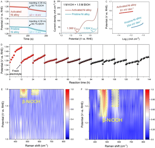
Finally, we replace MeOH with ethanol (EtOH) to further prove the universality of hydrogen production assisted by the electrooxidation of alcohol molecules and to deeply study the underlying mechanism. Similar to the MeOH-involving electrochemical test, the OCP changes when EtOH is injected into the electrolyte, and the change of OCP for the activated Ni alloy is more distinct (Fig. 4A), confirming a stronger response to EtOH. Then, the LSV curves of the pristine and activated Ni alloy were collected in the electrolyte with 1.5 M EtOH. It can be clearly seen that the activated alloy has a much larger current density than that of the pristine alloy (Fig. 4B). The overpotential at 100 mA cm−2 drops from 1.524 VRHE for the neat alloy to 1.366 VRHE for the activated alloy, along with a significant decrease in the Tafel slope from 254 to 91 mV dec−1 (Fig. 4C). During the long-term chronopotentiometric test, the electrolyte was replenished every 12 hours, and there was no obvious potential decline after 144 h, indicating that the designed metal electrode has good stability. In order to clarify the evolution of active species at the surface, in situ Raman tests are performed to dynamically monitor the electrocatalytic reaction (Fig. S17 and S18†). As shown in Fig. 4E, slight signals at 472 and 543 cm−1, corresponding to β-NiOOH,28,29 are observed when a relatively higher potential of 1.6 VRHE is applied to the activated Ni alloy. Such high-valence metal oxyhydroxides have been confirmed as the key active intermediates for the anodic OER and AOR.30,31 For the ethanol oxidation reaction (EOR), β-NiOOH starts to appear at a very small potential of 1.1 VRHE, and the signal intensity gradually increases with increasing potentials (Fig. 4F). The ease of formation of NiOOH and more NiOOH involved in the reaction indicate a faster kinetics and a higher intrinsic oxidation activity (Fig. 4G and H). Therefore, it is concluded that the electrochemical activation strategy allows fast formation of NiOOH at the surface of the Ni alloy, facilitating the oxidation of small organic molecules at a lower potential.
From the above analyses, the reaction mechanisms are schematically unveiled (Fig. 5). As discussed above, in situ electrochemical activation converts low-valence metal species to high-valence metal species on the Ni alloy surface, where the coordinated oxygen anions in NiOOH can effectively adjust the d-band center of Ni sites, increasing Ni–O covalency and thereby further enhancing the catalytic activity.32,33 Also, compared to low-valence metal species, NiOOH species have stronger adsorption to water and alcohol molecules before the reaction.32,34 Since the oxidation potential of alcohols is lower than that of water oxidation, the adsorbed alcohol molecules are quickly oxidized. According to the HPLC results, the main oxidation products of both methanol and ethanol are primarily carboxylic acids with a high yield and selectivity (Fig. S19†), indicating a strong oxidizing effect. In conclusion, the use of in situ electrochemical activation to construct high-valence metal species on the Ni alloy surface to generate more active sites and enhance the adsorption of alcohols is an effective strategy for hydrogen production.
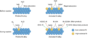 | ||
| Fig. 5 Schematic illustration of the electrocatalytic reaction mechanism over pristine and activated Ni alloys. | ||
Conclusions
In summary, we reported a simple route to in situ electrochemical activation on nickel (Ni) alloys for water splitting assisted by the electro-oxidation of organic molecules. Our findings revealed that in situ electrochemical activation leads to an increased degree of metal oxidation, thereby inducing the formation of more high-valence active metal species. Consequently, the activated Ni alloy showed a significantly lower overpotential (337 mV at 100 mA cm−2) and Tafel slope (48.3 mV dec−1) in comparison to the pristine Ni alloy. The introduction of organic molecules such as methanol and ethanol further promoted the water electrolysis. Through combined electrochemical testing and in situ Raman spectroscopy, we observed that the activated Ni alloy exhibited a stronger response to the adsorbed alcohol molecules and tended to form β-NiOOH at lower potentials compared to the pristine Ni alloy. This work demonstrated that in situ electrochemical activation is an effective strategy to facilitate efficient alcohol oxidation-assisted water electrolysis.Data availability
All data for the replication of this work are given in the ESI† or can be obtained by the lead contact upon reasonable request.Conflicts of interest
There are no conflicts to declare.Acknowledgements
This work is financially supported by the Anhui Provincial Natural Science Foundation (1908085QB83) and the Research Start-up Fund of Anhui University (S020118002/011). The authors would like to thank Dr Yongchao Zhang at Anhui University for TEM characterization, and A/Prof. Fuyang Cao at Jiangsu University for the nanoindentation test.References
- Y. Li, X. Wei, L. Chen and J. Shi, Angew. Chem., Int. Ed., 2021, 60, 19550–19571 CrossRef CAS PubMed.
- C. Tang, Y. Zheng, M. Jaroniec and S. Z. Qiao, Angew. Chem., Int. Ed., 2021, 60, 19572–19590 CrossRef CAS PubMed.
- X. Wu, Y. Wang and Z.-S. Wu, Chem, 2022, 8, 2594–2629 CAS.
- M. T. Bender, X. Yuan and K.-S. Choi, Nat. Commun., 2020, 11, 4594 CrossRef CAS PubMed.
- H. Zhou, Z. Li, L. Ma and H. Duan, Chem. Commun., 2022, 58, 897–907 RSC.
- G. Dodekatos, S. Schünemann and H. Tüysüz, ACS Catal., 2018, 8, 6301–6333 CrossRef CAS.
- N. Sauermann, T. H. Meyer, Y. Qiu and L. Ackermann, ACS Catal., 2018, 8, 7086–7103 CrossRef CAS.
- M. Yu, E. Budiyanto and H. Tüysüz, Angew. Chem., Int. Ed., 2022, 61, e202103824 CrossRef CAS PubMed.
- X. Han, G. Wu, S. Zhao, J. Guo, M. Yan, X. Hong and D. Wang, Matter, 2023, 6, 1717–1751 CrossRef CAS.
- Y. Zeng, M. Zhao, Z. Huang, W. Zhu, J. Zheng, Q. Jiang, Z. Wang and H. Liang, Adv. Energy Mater., 2022, 12, 2201713 CrossRef CAS.
- L. Magnier, G. Cossard, V. Martin, C. Pascal, V. Roche, E. Sibert, I. Shchedrina, R. Bousquet, V. Parry and M. Chatenet, Nat. Mater., 2024, 23, 252–261 CrossRef CAS PubMed.
- N. C. S. Selvam, L. Du, B. Y. Xia, P. J. Yoo and B. You, Adv. Funct. Mater., 2021, 31, 2008190 CrossRef CAS.
- G. Zhao, K. Rui, S. X. Dou and W. Sun, J. Mater. Chem. A, 2020, 8, 6393–6405 RSC.
- https://periodictable.com/Properties/A/AtomicRadius.an.pr.html .
- F. Liang, Z.-X. Wang, Y.-W. Luo, B. Zhang, X.-M. Luo and G.-P. Zhang, Acta Mater., 2021, 216, 117138 CrossRef CAS.
- D. S. Hall, C. Bock and B. R. MacDougall, J. Electrochem. Soc., 2013, 160, F235 CrossRef CAS.
- C. Kuai, Y. Zhang, D. Wu, D. Sokaras, L. Mu, S. Spence, D. Nordlund, F. Lin and X.-W. Du, ACS Catal., 2019, 9, 6027–6032 CrossRef CAS.
- A. P. Grosvenor, M. C. Biesinger, R. C. Smart and N. S. McIntyre, Surf. Sci., 2006, 600, 1771–1779 CrossRef CAS.
- S. Tougaard, J. Vac. Sci. Technol., A, 2021, 39, 011201 CrossRef CAS.
- A. Bergmann, T. E. Jones, E. M. Moreno, D. Teschner, P. Chernev, M. Gliech, T. Reier, H. Dau and P. Strasser, Nat. Catal., 2018, 1, 711–719 CrossRef CAS.
- H. Ren, Y. Pan, C. C. Sorrell and H. Du, J. Mater. Chem. A, 2020, 8, 3154–3159 RSC.
- S. Wang, J. Zhang, O. Gharbi, V. Vivier, M. Gao and M. E. Orazem, Nat. Rev. Methods Primers, 2021, 1, 41 CrossRef CAS.
- Z. Xiao, Y.-C. Huang, C.-L. Dong, C. Xie, Z. Liu, S. Du, W. Chen, D. Yan, L. Tao, Z. Shu, G. Zhang, H. Duan, Y. Wang, Y. Zou, R. Chen and S. Wang, J. Am. Chem. Soc., 2020, 142, 12087–12095 CrossRef CAS PubMed.
- Y. Wang, W. Yan, M. Ni, C. Zhu and H. Du, Chem. Commun., 2023, 59, 2485–2488 RSC.
- J. L. Gilbert and P. Khullar, J. Electrochem. Soc., 2020, 167, 021505 CrossRef CAS.
- E. Pastor, Z. Lian, L. Xia, D. Ecija, J. R. Galán-Mascarós, S. Barja, S. Giménez, J. Arbiol, N. López and F. P. G. de Arquer, Nat. Rev. Chem., 2024, 8, 159–178 CrossRef PubMed.
- N. Heidary and N. Kornienko, Chem. Sci., 2020, 11, 1798–1806 RSC.
- W. Du, Y. Shi, W. Zhou, Y. Yu and B. Zhang, Angew. Chem., Int. Ed., 2021, 60, 7051–7055 CrossRef CAS PubMed.
- W. Chen, C. Xie, Y. Wang, Y. Zou, C.-L. Dong, Y.-C. Huang, Z. Xiao, Z. Wei, S. Du and C. Chen, Chem, 2020, 6, 2974–2993 CAS.
- H. Zhong, Q. Zhang, J. Yu, X. Zhang, C. Wu, Y. Ma, H. An, H. Wang, J. Zhang, X. Wang and J. Xue, Adv. Energy Mater., 2023, 13, 2301391 CrossRef CAS.
- Q. Xue, Z. Xia, W. Gou, J. Bu, J. Li, H. Xiao and Y. Qu, ACS Catal., 2023, 13, 400–406 CrossRef CAS.
- Y. Qi, Y. Zhang, L. Yang, Y. Zhao, Y. Zhu, H. Jiang and C. Li, Nat. Commun., 2022, 13, 4602 CrossRef CAS PubMed.
- C. Liu, F. Yang, A. Schechter and L. Feng, Advanced Sensor and Energy Materials, 2023, 2, 100055 CrossRef.
- L. Lai, G. Yang, Q. Zhang, H. Yu and F. Peng, J. Power Sources, 2021, 509, 230397 CrossRef CAS.
Footnote |
| † Electronic supplementary information (ESI) available. See DOI: https://doi.org/10.1039/d4ta02707h |
| This journal is © The Royal Society of Chemistry 2024 |

