
 Open Access Article
 This Open Access Article is licensed under a Creative Commons Attribution-Non Commercial 3.0 Unported Licence
Hydroxyl-conductive 2D hexagonal boron nitrides for anion exchange membrane water electrolysis and sustainable hydrogen production†
Jasneet
Kaur
 *abc,
Matthew
Schweinbenz
b,
Kane
Ho
a,
Adel
Malekkhouyan
a,
Kamal
Ghotia
d,
Franz
Egert
de,
Fatemeh
Razmjooei
*d,
Syed Asif
Ansar
d and
Hadis
Zarrin
*a
*abc,
Matthew
Schweinbenz
b,
Kane
Ho
a,
Adel
Malekkhouyan
a,
Kamal
Ghotia
d,
Franz
Egert
de,
Fatemeh
Razmjooei
*d,
Syed Asif
Ansar
d and
Hadis
Zarrin
*a
aDepartment of Chemical Engineering, Nano-Engineering Laboratory of Energy and Environmental Technologies, Toronto Metropolitan University, Toronto, Ontario M5B 2K3, Canada. E-mail: hadis.zarrin@torontomu.ca
bDepartment of Physics, Brock University, 1812 Sir Isaac Brock Way, St Catharines L2S 3A1, Ontario, Canada
cYousef Haj-Ahmad Department of Engineering, Brock University, 1812 Sir Isaac Brock Way, St Catharines L2S 3A1, Ontario, Canada
dInstitute of Engineering Thermodynamics, German Aerospace Center (DLR), Pfaffenwaldring, 38-40, 70569 Stuttgart, Germany
eUniversity of Stuttgart, Faculty 6 – Aerospace Engineering and Geodesy, 70569 Stuttgart, Germany
First published on 16th January 2025
Abstract
In response to the urgent global call to transition from polluting fossil fuels to sustainable energy alternatives, hydrogen emerges as a promising and widely accessible energy source if it can be efficiently produced through water splitting and electrolysis. Anion exchange membrane (AEM) water electrolyzers (AEMWEs) have potential for large scale H2 production at a low cost. However, the development of alkaline membranes with high hydroxide conductivity, improved stability and better performance is a significant challenge for the commercial application of advanced AEMWEs. In this work, a novel structure for hydroxide-ion conductive membranes based on surface-engineered two-dimensional (2D) hexagonal boron nitrides (h-BN) is designed and validated in a highly active and durable AEMWE cell with non-precious metal Ni-based electrodes. Among two samples, the high-loaded 2D hBN nanocomposite membrane (M2) showed significantly high hydroxide-ion conductivity (190 mS cm−1) with improved electrochemical and mechanical stability. The AEMWE cell assembled with the M2 membrane exhibited superior cell performance, achieving 1.78 V at 0.5 A cm−2 compared to the cell utilizing the lower loading hBN nanocomposite membrane (M1). Additionally, its performance closely approached that of the cell employing a commercial membrane. During a long-term stability test conducted at a constant load of 0.5 A cm−2 for 250 hours, the M2 membrane maintained satisfactory electrolysis voltage without any notable failure. These findings demonstrate that 2D hBN nanocomposite membranes hold great promise for use in advanced AEMWEs.
1 Introduction
Electrochemically generated hydrogen is a promising fuel for developing a climate-neutral energy economy.1,2 Great efforts are being made to improve established technologies like fuel cells and water electrolysers with rapidly growing interest in hydrogen technology.1–5 Hydrogen has several unique advantages as a climate solution, particularly in sectors that are most difficult to decarbonize and are considered as the toughest category of emissions, which includes trucking, shipping, and the production of steel, and cement.5 Hydrogen offers new hope for combating the climate change and fueling the economy by clean and sustainable technologies.3,6 Low-temperature water electrolysis is one of the cutting-edge technologies to generate high-purity hydrogen for the sustainable conversion of hydrogen from renewable energy, using water.6–8 This technology offers adequate energy storage and grid-balancing utility in power-to-gas operations. The advantages offered by low-temperature water electrolysis include its high efficiency, high product purity, stable output, the feasibility of large-scale production and the capability of incorporating renewable energy as the power source.9There are three major types of low temperature water electrolyzers: conventional alkaline electrolyzers, proton-exchange-membrane (PEM) water electrolyzers (PEMWEs), and anion-exchange-membrane (AEM) water electrolyzers (AEMWEs).1,9 Currently, the major commercially available water electrolysis technologies are PEMWE and alkaline electrolysis. PEM electrolysis can reach a high performance of 3000 mA cm−2 at 1.8 V.1 PEMWE is promising but limited by the necessity to use precious platinum and iridium electrocatalysts, Nafion-based PEM and titanium stacking components, which directly increase the capital cost of the electrolysis process, hence hindering the wider applications of this technology.1,10 On the other hand, alkaline electrolysis is a mature and less expensive technology, but it cannot be linked with renewable electricity (solar, wind, etc.) for hydrogen generation. This is mainly due to the inability of alkaline electrolyzers to maintain high-pressure hydrogen, because of the required use of a porous diaphragm and circulation of the liquid electrolyte.11 Inspired by the PEMWE configuration, AEMWEs based on AEMs can be developed to replace the liquid electrolyte with a polymer electrolyte; thus, they do not require the circulation of a liquid electrolyte. AEMWEs combine the advantages of using low-cost and abundant electrocatalyst materials with the benefits of PEMWEs, namely, a low carbon footprint, large operational capacity, and a fast response to changing operating conditions.6 AEM electrolysis technology operates in an alkaline environment (pH ∼10), making the use of modest non-noble-metal electrocatalysts possible, while accommodating zero-gap architecture. Similar to PEMWEs, the membrane-based design allows a differential pressure operation and reduction in the size and weight of the electrolyser.12 Nevertheless, AEMs can be made of hydrocarbons only, which are less expensive than the perfluorinated membranes used in PEMWEs.12,13
A schematic of the components and the electrochemical processes that occur in an AEMWE is shown in Fig. 1. The key component for AEMWE is a stable and highly hydroxide conductive polymeric AEM, which can be produced by inexpensive materials and methods.14 The AEMWE single cell is separated into two half-cells by the anion exchange membrane. Each half-cell consists of an electrode, a gas diffusion layer (GDL), and a bipolar plate (BPP). The hydroxide-ion conducting AEM is sandwiched by two electrodes, the anode, and the cathode. The power supply from the external circuit is used to create an electrical potential difference at the interface of the electrolyte and electrode. The potential difference then drives the hydrogen evolution reaction (HER) by means of electron (e−) transfer and reducing a water molecule at the cathode side to produce the H2.14 The hydroxide ion (OH−) from the HER will return to the anode half-cell via the membrane and it is oxidized by the oxygen evolution reaction (OER) to produce O2.15
 | ||
| Fig. 1 Schematic of the components and the electrochemical processes that occur in AEMWEs showing the chemical structure of the developed hydroxyl-conductive hBN-based AEM. | ||
Ideal AEM candidates should exhibit high hydroxide-ion conductivity and low permeability to the generated fuels (e.g., H2), while maintaining robust mechanical integrity and chemical stability under electrolysis operating conditions. Most AEMs are typically prepared from aromatic polymers with quaternary ammonium groups (–NR3+) distributed along the polymer backbones, such as quaternized poly(arylene ether sulfone), poly(phenylene oxide), poly(phenylene) and radiation-grafted fluorinated polymers.11,16 These membranes are relatively inexpensive and have low interaction with atmospheric CO2. Thus, it is expected that this electrolysis technology should offer better performance at a lower overall cost.14 However, low hydroxide-ion conductivity (80–120 mS cm−1 at 80 °C) was widely observed for these AEMs and impeded the progress of high performance AEMs.17 To circumvent this obstacle and pursue higher hydroxide-ion conductivity, several researchers have imitated the strategies applied in designing the PEMs.14,18 Similar to PEMs, side-chain-type and multiblock polymer structure AEMs have been proved to be effective for promoting hydroxide-ion conductivity, but suffer from deteriorating dimensions and poor alkaline stability.11 Although extensive research on this class of polymers is still underway, the fine controls over the topological structures of these polymers and the nanoscale morphology are unsatisfactory.12,19 In addition, since the use of pure water or a low concentration of the alkaline solution instead of concentrated alkaline electrolytes is highly demanded in AEMWEs, it is vital to develop an AEM that can possess high hydroxide conductivity and endurance under such conditions. Last but not the least, to have a low ohmic loss comparable to that in PEMs, it is required to develop thinner AEMs with high hydroxide-ion conductivity, yet maintaining the mechanical integrity, electrochemical stability under alkaline conditions, and impermeability to the evolved gases.20
One of the promising strategies to redesign the structure of AEMs is the use of two-dimensional (2D) nanofillers, which can offer important properties such as durability and strength to the structure along with increasing ionic conductivity and ion-exchange capacity of the developed AEMs.18–21 However, when the surface or porous structure of these 2D nanofillers were modified with distilled (DI) water and alkaline ionomers, the performance and durability of AEM electrolyzers became lower (<1 A cm−2 at 2 V).22 To achieve the performance standards required for AEMs in water electrolysers, 2D hexagonal boron nitride (hBN) nanoflakes have been used for the first time as nanofillers in this work, for constructing solid-state hydroxyl ion-conductive electrolytes. Using a simple and low-cost synthesis route, the surfaces of 2D hBN nanoflakes are engineered and functionalized with Sustainion® XA9 alkaline ionomers, which consist of alkaline-stable imidazolium ligands with high ionic conductivity. The physical, chemical, mechanical, and electrochemical properties of the novel 2D hBN-based AEM have been investigated by various microscopic and spectroscopic characterization tests. The hBN-based and commercial AEMs are sandwiched between two non-precious, porous nickel-based electrodes (for more information please see the Experimental section of the ESI†) and tested in a single AEMWE cell using polarization curves and chronoamperometric measurements at a constant current density of 0.5 A cm−2, carried out in 1 M KOH at 60 °C. The introduction of hBN-based membranes into the cell has successfully minimized the gas diffusion and increased the stability under the constant load of 0.5 A cm−2 for 250 h. The negligible degradation of the cell without failure can be attributed to the high mechanical and chemical stability of 2D hBN-based AEMs, making them a great candidate for AEMWEs. More investigation is still needed to further increase the durability of membranes, which will be considered in future work.
2 Results and discussion
2.1 Fabrication of hydroxyl-conductive hBN AEMs
Fig. 2a shows the schematic for the synthesis and functionalization of 2D hBN nanoflakes performed by the liquid exfoliation technique.20 A specific amount of bulk powder of hBN was dispersed in isopropanol and simultaneously exfoliated and functionalized with Sustainion® (XA-9 alkaline ionomer 5% in ethanol, purchased from Dioxide Materials) in the presence of KOH as detailed in the ESI.†Fig. 2b shows the schematic for the fabrication of the 2D hBN based hydroxyl conductive membrane. Sustainion® acted as a dual functional material in this process: (i) generating abundant hydroxide-conductive sites on the high surface area of hBN and (ii) assisting the exfoliation process of hBN and increasing the number of exfoliated layers by bonding at the N-sites of hBN nanoflakes leading to edge functionalization of 2D hBN as confirmed by Raman spectra of functionalized hBN. KOH also contributed to the exfoliation and hydroxylation of hBN nanoflakes. The mechanism of functionalization is elaborated and validated in the following sections. The collected suspension obtained after tip sonication and centrifugation, which consisted of few-layered functionalized 2D hBN nanoflakes with hydroxyl-conductive groups of Sustainion, was used as a nanofiller for constructing the anion exchange membranes (AEMs), the detailed procedure is discussed in the ESI.† Two samples with different loadings of the BN-OH nanofiller (M1: 15 wt% of functionalized hBN and M2: 25 wt% of functionalized hBN) were cast as hydroxyl conductive membranes using polyvinyl alcohol (PVA) as the polymer matrix.23,24 The polymer matrix of PVA acts as the backbone for AEMs which helps in providing structural integrity, and mechanical and thermal stability to the structure of the membrane. It also supports hydroxyl ion conduction in the AEM which is due to the interactions with water molecules and polymer dynamics.23,24 Over the period, we have produced multiple batches of these membranes to confirm the reproducibility of the membrane structure, physical and chemical properties. We have observed that in at least over 20 batches of membranes produced with precise calculations, the produced structures have been consistent in terms of structural and mechanical properties, electrochemical properties and performance, which proves the reliability of the fabrication procedure. | ||
| Fig. 2 (a) Schematic of the synthesis of functionalized hBN nanoflakes and casting of the hydroxyl conductive hBN membrane. (b) Reaction mechanism during the exfoliation process. | ||
2.2 Structural and compositional characterization of nanoflakes and hBN-based AEMs
Fig. 3a shows the FTIR spectra of hBN and functionalized hBN. The peaks observed at 1183 cm−1 and 812 cm−1 correspond to B–N stretching and bending in the hBN nanoflakes.25,26 In the functionalized hBN, the peaks at 1397 cm−1 and 702 cm−1 correspond to B–N stretching and bending respectively, 1080 cm−1 corresponds to C–O stretching, 2937 cm−1 corresponds to C–H stretching, and the broad peak at 3414–3195 cm−1 is due to O–H stretching.19 This shows attachment of the Sustainion molecules onto the BN nanoflakes through the O–H, C–H and C–O bonds being present along with the BN peaks. Fig. 3b shows the Raman spectra of hBN and functionalized hBN, with both showing the strong E2g mode of hBN.20,26 Compared to the peak that bulk hBN has at 1366 cm−1, the Sustainion functionalized and unfunctionalized hBN have peaks observed at 1367.5 cm−1 and 1368 cm−1 respectively, corresponding to a thickness of three layers for both samples, with fewer layers providing a greater Raman shift.25,27 In the Raman spectra of functionalized hBN, peaks observed at 1446 cm−1 correspond to C–H bonding, as well as peaks at 1537 cm−1, 1580 cm−1, and 1600 cm−1 correspond to C–N bonding which confirm that the nitrogen sites are bonded with the Sustainion.28 | ||
| Fig. 3 Structural characterization of hBN dispersions and membranes M1 and M2: (a) FTIR of hBN and functionalized hBN; (b) Raman spectra of hBN and functionalized hBN; (c) FTIR of membranes; (d) Raman spectra of membranes; inset: photo of the M2 membrane. | ||
In the FTIR spectra of M1 and M2 shown in Fig. 3c and compared to the FTIR spectrum of PVA alone shown in Fig. S1,† the peaks corresponding to B–N stretching are at 815 cm−1 and 1385 cm−1.26,29 In M1 and M2, the peaks at 1090 cm−1 correspond to C–O stretching, 1635 cm−1 corresponds to C![[double bond, length as m-dash]](https://www.rsc.org/images/entities/char_e001.gif) C stretching, the peak corresponding to 2950 cm−1 is attributed to C–H stretching and the broad peaks in between 3210 and 3380 cm−1 are due to O–H stretching.20Fig. 3d shows the Raman spectra of the membranes M1 and M2. Strong peaks at 1366 cm−1 present the high-frequency interlayer Raman active E2g mode of exfoliated hBN.20,30 The Raman peak at 1000 cm−1 corresponds to C–C aromatic chain vibrations, due to both PVA and Sustainion.31,32
C stretching, the peak corresponding to 2950 cm−1 is attributed to C–H stretching and the broad peaks in between 3210 and 3380 cm−1 are due to O–H stretching.20Fig. 3d shows the Raman spectra of the membranes M1 and M2. Strong peaks at 1366 cm−1 present the high-frequency interlayer Raman active E2g mode of exfoliated hBN.20,30 The Raman peak at 1000 cm−1 corresponds to C–C aromatic chain vibrations, due to both PVA and Sustainion.31,32
Fig. 4a–d show the XPS elemental analysis of hBN and functionalized hBN dispersions deposited on silicon wafer. According to Fig. 4a, the functionalization of hBN nanoflakes with Sustainion significantly decreases the intensity of the B–N peak at 190.5 eV in the high-resolution convoluted XPS spectra of B 1s, which is in agreement with the previously reported values of the B–N peak position in functionalized BN systems.29 This is due to the formation of B–C and B–O bonds at 191.0 eV and 192.0 eV, respectively.33 It is interesting to note that the N–B peak at 399.23 eV in the deconvoluted spectra of N 1s (Fig. 4b) is shifted to 398.11 eV, which is due to the formation of N–C in functionalized hBN.33 This decrease in peak intensity and shifting of peak values is attributed to the disruption of the B–N covalent bond due to chemical functionalization and the rebinding of B and N elements with Sustainion molecules. Additional peaks are observed in C 1s at 292.78 eV and 295.55 eV in functionalized hBN (Fig. 4c), which are from K 2p due to the presence of KOH in the functionalized hBN suspension, in addition to an additional peak at 288.34 eV, which is due to C–N/C–OH bond formation.33–35Fig. 4d shows the elemental spectra of O 1s, the peak is observed at 532.69 eV for hBN and shifted to 530.83 eV for functionalized hBN with a shoulder peak at 532.28 eV which is due to the formation of B–O, B–OH and O–C bonds.36,37 These changes in peak values show the effects of surface functionalization and edge hydroxylation in the B–N structure which is also observed through the results obtained from FTIR and Raman spectroscopies. These modifications in the XPS spectra of functionalized hBN confirm the successful surface functionalization based on the mechanism shown in Fig. 2. To further validate the existence of functionalized hBN after the fabrication of AEMs, we performed the XPS analysis on our best performing membrane (M2). Fig. S2† shows the elemental spectra of M2 and the deconvoluted spectra of B 1s, N 1s, C 1s and O 1s, respectively. The deconvoluted spectra of B 1s and N 1s show peaks of same intensity and peak values at 190.4 eV and 398.06 eV which conform with the previously reported values of the B–N peak position in functionalized BN systems.20 The XPS peaks of C 1s show the presence of the C–C peak at 285 eV and CN/C–N peaks at 286.1 eV.38 The peak corresponding to O 1s is observed at 532 eV.20
 | ||
| Fig. 4 XPS elemental analysis of hBN and functionalized hBN for (a) B 1s, (b) N 1s, (c) C 1s, and (d) O 1s. | ||
The hexagonal structure of hBN was maintained after being hydroxylated and functionalized with Sustanion, which was confirmed by the scanning electron microscopy (SEM) images in Fig. 5a and b. These images also displayed lateral dimensions in the range of 10–20 μm for hBN flakes and 30–40 μm for functionalized hBN. The cross-sectional SEM image of the M2 membrane in Fig. 5c shows the presence of functionalized hBN flakes in the M2 sample. Fig. 5d–h display the EDS elemental mapping of M2 confirming the presence of C, O, B and N with the corresponding mass percentages of 65.7, 29.7, 3.4, and 1.2%, respectively.
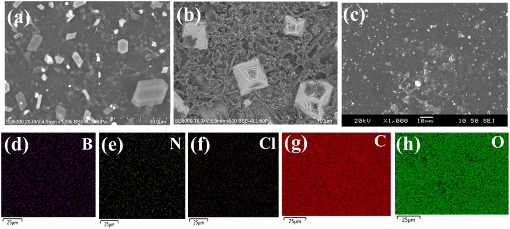 | ||
| Fig. 5 SEM images of (a) hBN nanoflakes, (b) functionalized hBN nanoflakes, (c) cross-section of M2 membrane, (d)–(h) EDS elemental mapping of M2. | ||
2.3 Electrochemical, physical, and mechanical properties of hBN AEMs
Fig. 6a and b show the in-plane and through-plane hydroxyl conductivities of M1 and M2 samples as a function of temperature at a relative humidity (RH) of 100%. In both in-plane and through-plane directions, the highest values of conductivities of M1 (in plane conductivity = 55 mS cm−1, through plane conductivity = 0.66 mS cm−1) and M2 (in plane conductivity = 190 mS cm−1, through plane conductivity = 1.31 mS cm−1) membranes are observed at elevated temperatures beyond 70 °C, indicating accelerated ion mobility at elevated temperatures. These values of in-plane and through-plane conductivities are much higher than those observed for PVA alone (Fig. S3†). At temperatures above 70 °C and 100% RH, the in-plane conductivities of 2D hBN based samples (M1 and M2) were high, in the order of 10−2 S cm−1 for 15 wt% of hBN nanofiller and 10−1 S cm−1 for 25 wt%. However, the through-plane values were relatively lower, in the order of 10−4 S cm−1 for 15 wt% of hBN nanofiller and 10−3 S cm−1 for 25 wt% of hBN nanofiller. The highly anisotropic hydroxyl ion conduction is attributed to the structural and morphological anisotropy of 2D nanoflakes. These hydroxyl ion conductivity values were the highest among the state-of-the-art AEMs and comparable to the proton conductivities of commercial PEMs (e.g., Nafion), showing promise for few-layer and single layer 2D hBN nanoflakes as 2D building blocks for constructing high-performance inorganic AEMs.14,39,40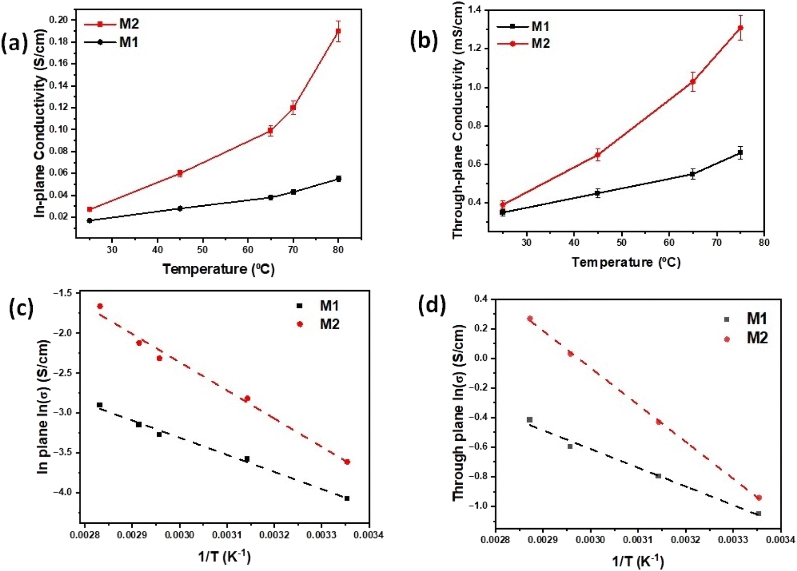 | ||
| Fig. 6 (a) In-plane hydroxyl conductivity, (b) through-plane hydroxyl conductivity, (c) Arrhenius plots of in-plane and (d) Arrhenius plots of through plane conductivity of M1 and M2 membranes as a function of temperature at 100% RH. | ||
The activation energies (Ea) of the samples are calculated using in-plane and through-plane Arrhenius plots, and values of 0.15 eV and 0.11 eV for M2 and M1 in plane and 0.12 eV and 0.09 eV for M2 and M1 through plane, respectively, were achieved as shown in Fig. 6c and d. The activation energies of all the membranes are in the range of 0.11–0.21 eV, indicating that Grotthuss mechanism is the dominant mechanism of ion conduction, where the single hydroxide ions can hop between two neighboring ion-conductive groups without any carrier molecules.41 M1 and M2 with higher activation energies exhibited higher hydroxyl conductivities due to their significantly higher concentration of mobile ions, validated by high ion-exchange capacity (IEC) values presented in Fig. 7a and analyzed in the next paragraph. It is predicted that the surface hydroxyl functional groups on hBN can form a stable hydrogen bonding network with water molecules, where the hydroxide ion exhibits a quasi-2D conduction behavior along the adjacent layer of water molecules near the positively charged 2D hBN nanoflakes.42 We concluded that the membrane structure strongly depends on the surrounding water molecules and OH− ions from the Sustainion ionomer and hydroxylated hBN. The OH− is transported through the hydrogen bond network in water molecules by forming an [H3O2]− conjugate which cleaves into H2O and OH−.40 In the presence of trapped water molecules, large amounts of hydroxide ions can dissociate from the functionalized nanoflakes, which then form hydrated hydroxide ions. After functionalization, the enlarged d-spacing of functionalized hBN nanoflakes calculated based on Bragg's law using the results from Fig. S4† gives more spaces for the hydrated hydroxide ions to migrate faster via the Grotthuss mechanism.43 The hypothesis for the ion conduction mechanism is based on the unique structure and chemical composition of AEMs. The synthesized AEMs in this work consist of 2D hBN as a nanofiller, Sustainion as an ionomer and functionalizer, and PVA as a polymer to provide support and facilitate hydroxide ion mobility and conduction. Few-layered and single-layered 2D nanomaterials such as layered double hydroxides (LDHs) have been studied as anion conductors and single layered 2D LDHs have shown exceptionally high in-plane hydroxide ion conductivity approaching 10−1 S cm−1 by Sun et al.41,42 This special effect is attributed to the 2D confinement-induced highly anisotropic hydroxyl ion conduction in LDH nanosheets, which is considered an intrinsic characteristic of these peculiar 2D materials.
 | ||
| Fig. 7 (a) Water uptake (%) ratio, crosswise and longitudinal swelling ratio (%), and IEC (mequiv. g−1) plots of membranes. (b) Alkaline electrochemical stability of membranes. (c) Tensile strength measurements. | ||
In this work, we used another type of 2D material, 2D hBN as a nanofiller in creating AEM structures, where we observed a similar pattern of exceptionally high in-plane hydroxyl ion conductivity. In our understanding, the unique 2D structure of hBN plays a key role in leading to high ionic conductivity, electrochemical stability and mechanical integrity of the synthesized AEMS (M1 and M2). Being a 2D nanomaterial, 2D hBN provides 2D confinement-induced highly anisotropic hydroxyl ion conduction within the AEM structure. In addition, Sustainion ionomer functionalizes 2D hBN and engineers its surface in creating ion conduction pathways within the AEM structure. We studied the effect of temperature variation on the ionic conductivity of AEMs in a humidified environment and observed an increasing trend in the hydroxide conductivity with the increase of temperature at RH = 100%. We believe that the adsorbed water molecules on functionalized 2D hBN underwent a self-dissociation process to generate protons and hydroxyl ions, as observed earlier in LDH studies and the self-dissociation increased with temperature.41,42 Therefore, at elevated temperatures, a higher concentration of hydroxyl ions would be produced which facilitate ion conduction. Because of the positive charges of functionalized 2D hBN host layers, hydroxyl ions were attracted and propagated along the hydrogen bond networks of adsorbed water molecules through high-frequency hydrogen bond breaking and reformation. This led to the formation of a space-charge zone with an increased hydroxyl ion concentration around 2D hBN host layers. The generated hydroxyl ions were rapidly conducted, which broke the water self-dissociation equilibrium, leading to the continuous generation of a sufficient flow of hydroxyl ions in AEMs.
In addition, PVA supports hydroxide ion conduction in AEMs, as the –OH groups in PVA provide high-density Grotthuss mechanism conduction sites like water. The PVA backbone is crosslinked to form a semi-interpenetrating network of PVA and functionalized 2D hBN; the resulting material contains PVA chemical crosslinks and hydrogen bonds between PVA and functionalized 2D hBN which lead to higher ionic conductivity and enhanced mechanical strength in M1 and M2 membranes. Using the conductivity vs. temperature experiment in a humidified environment, we demonstrated that the Grotthuss mechanism is the primary ion conduction mechanism in AEMs. The conductivity of M1 and M2 increased with increasing temperature and the maximum value of M2 reached 190 mS cm−1 at 70 °C, with lower values of activation energy confirming the presence of the Grotthuss mechanism in AEMs.
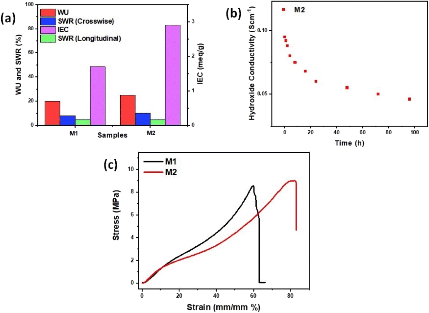
Due to the hydrophilic nature of functionalized groups in hBN flakes as well as hydrophilic sites of PVA chains, there is an increased ionic mobility of hydroxyl ions in M1 and M2 membranes which is not only responsible for the increased ionic conductivity but also leads to the increased values of IEC measured by the back titration method detailed in the ESI† and the calculated IEC values are shown in Table S1.†Fig. 7a compares the water uptake (WU), crosswise and longitudinal swelling ratio (SWR), and ion-exchange capacity (IEC) plots of M1 and M2. It is interesting to note from Table S1† and Fig. 7a that the IEC values are almost double in M2 as compared to M1, whereas the water uptake and swelling ratios of M1 and M2 are almost equal. The observations suggest that, while 2D hBN-based membranes exhibit much lower WU and crosswise and longitudinal SWRs, these structures demonstrate significantly higher IEC. The lower WU and SWRs in hBN-based AEMs can be attributed to the hydrophobic nature of hBN itself, which leads to a decreased surface intake of water molecules, resulting in better dimensional integrity and lower SWRs of hBN-based membranes. Moreover, in contrast to the decrease in WU and SWRs in hBN-based membranes, the abundantly available surface area provided by hBN nanoflakes accommodates many hydroxyl-conductive sites of Sustainion, leading to a significant increase in IEC compared to the commercial membrane. The ion-conductive groups and 2D hBN nanofiller in M1 and M2 contribute to not only improving the ionic conductivity but also improving the physicochemical and electrochemical properties of the hydroxyl conductive membranes.
Fig. 7b shows the alkaline electrochemical stability of M2. To evaluate the alkaline electrochemical stability, membrane M2 was held in a solution of 1 M KOH heated at 70 °C.44 After some time, the sample was rinsed and stored in DI water before remeasuring the hydroxide conductivity stability. It was observed that the membrane M2 maintained its in-plane ionic conductivity after the test and the conductivity of M2 was 50% reduced after 60 h of treatment in alkaline solution. This indicates that the functionalized hBN loading in the nanocomposite membrane resulted in more stable hydroxide conductivity as hydroxyl-functionalized 2D hBN helps in the retention of the structural integrity, durability and electrochemical stability of M2. The reduction in hydroxide conductivity of M2 is due to the degradation of the Sustainion ionomer in the structure of M2 at elevated temperatures.5
To study the effect of functionalized hBN loading on the mechanical strength of M2, the tensile test was performed. The typical stress–strain curves for M1 and M2 membranes are displayed in Fig. 7c. While commercial Sustainion membranes are commonly used owing to their anion exchange capabilities, they are very brittle.45 From tensile tests shown in Fig. 7c, it can be seen that the ultimate tensile strength of M1 sample is 8.6 MPa and that of the M2 sample is 9 MPa. With M2 as the highest performing sample with high loading hBN, an extended plastic region allows for strain to reach 83% before breaking at 8.76 MPa, which is significantly higher than some of the commercial membranes. This is due to the improved and robust structure of the composite formed by 2D hBN nanoflakes which have higher mechanical strength and PVA polymer offering flexibility and strength to the composite AEMs. As a result, 2D hBN-based polymer composite membranes (M1 and M2) offer attractive options for electrolyser use with significant improvements and durability in tensile strength.
2.4 Performance and durability evaluation of AEMWE cells with hydroxyl-conductive hBN AEMs
M1 and M2 membranes assembled with porous nickel-based electrodes (see the Experimental details in the ESI†) were implemented in the AEMWE cell to investigate their practical effects on the cell performance.15,46 For comparison, one cell is also assembled by using the Sustainion® X37-50 Grade RT Commercial Membrane (CS-M3) with the same cell components and tested under the same conditions. As shown in Fig. 8a, the membrane is simply sandwiched between two electrodes, the cathode and the anode with a gas diffusion layer (Ni mesh) and current collector at each side. Fig. 8b shows the polarization curves of AEMWE cells with M1, M2 and CS-M3 using Ni-based electrodes, operating at 60 °C and atmospheric pressure in 1 M KOH. The cell with the M2 membrane achieves a cell potential of 1.78 V at 0.5 A cm−2, which shows an improvement at the same current density compared to the cell with the M1 membrane (1.98 V at 0.5 A cm−2) and commercial CS-M3 membrane with 1.83 V. These results show that the introduction of the hydroxide-conductive 2D hBN-based M2 membrane into the cell successfully lowers the voltage at a given current density. This reduction in voltage directly translates to lower energy consumption, making the electrolysis process more cost-effective and environmentally friendly, particularly when powered by renewable energy sources. To evaluate the long-term performance of both M1 and M2 membranes, the durability of the cells with M1 and M2 membranes in 1 M KOH was evaluated under a current density of 0.5 A cm−2 at 60 °C. The results are shown in Fig. 8c and d as the cell-voltage changes versus time. Regardless of the initial cell performance, both cells with M1 and M2 were operated for 250 h without cell failure, which could be due to the good mechanical and chemical stability of the membranes. However, in the future work, we aim to extend durability tests beyond 250 hours by optimizing the functionalization process to further enhance the electrochemical and mechanical stability of the membranes. Table S2 of the ESI† compares the performance of the cell with the membranes used in this work with the reported literature.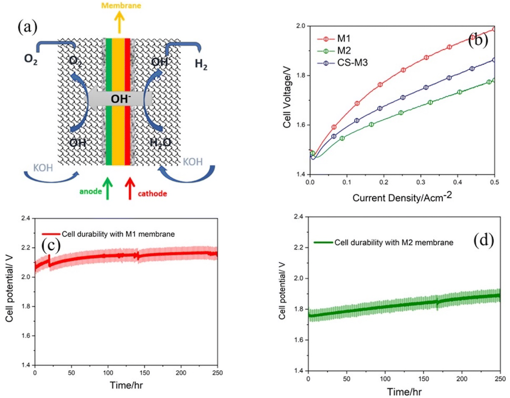 | ||
| Fig. 8 (a) AEMWE cell configuration. Electrochemical characterization of the AEMWE electrolyzer based on the cell configuration with Ni-based electrodes for both anode and cathode with different synthesized membranes M1 and M2 and commercial Sustainion® X37-50 (CS-M3) membrane at 60 °C. (b) Polarization curves for cells with M1 and M2 and commercial Sustainion® X37-50 (CS-M3) membranes, and durability test at a constant current density of 0.5 A cm−2 for (c) the cell with the M1 membrane and (d) M2 membrane. | ||
3 Conclusions
In summary, we have created a novel design and two new structures of hydroxyl ion conductive membranes using two different wt% of functionalized 2D hBN nanofiller with Sustainion ionomer. These hydroxyl-conductive membranes not only exhibit increased values of ionic conductivity, but also show improved electrochemical stability and mechanical durability of the membranes. We have shown that the presence of abundant hydroxyl-conductive groups near the surface of 2D hBN with high IEC values plays a vital role in OH− transportation in low alkalinity water electrolyzers (1 M KOH), which is crucial for advancing the efficiency, durability, and applicability of AEMWEs. Due to the unique structure of AEMS, specifically the presence of functionalized 2D hBN, supporting the polymeric platform and trapped water molecules on hydrophilic sites and hydroxylation of 2D hBN along with the hopping of OH− ions on the functionalized groups of 2D hBN nanoflakes, the hydroxyl conductivity values are high in the membranes. The values of activation energy led to the determination of the mechanism of ion conduction, which is the Grotthuss mechanism due to the unique 2D structure, functionalized chemical surface and hopping of hydrated OH− ions within 2D hBN nanoflakes and polymer chains. These membranes are tested in an AEMWE cell with the cell configuration of porous Ni-based electrodes for both anode and cathode and the performance and durability of the cell are studied, and results are compared with a commercial membrane. The cell with the M2 membrane (high-loaded functionalized 2D hBN) showed the highest cell performance of 1.78 V at 0.5 A cm−2 which was greater than the cell with the M1 membrane. Regardless of the initial cell performance, both cells with M1 and M2 were operated for 250 h without any cell failure, which is due to the high mechanical strength and chemical stability of the membranes.Data availability
The data supporting this article have been included as part of the ESI.† Other data are presented and analyzed within the main body of the article. We confirm that all data used in this study are original and were generated by the authors in the laboratories at Toronto Metropolitan University, Brock University, and Institute of Engineering Thermodynamics at German Aerospace Center (DLR). Origin Pro, PowerPoint, and Mole View were utilized to display the data, schematics, and reaction mechanisms.Author contributions
Jasneet Kaur: conceptualization, data curation, formal analysis, investigation, methodology, resources, validation, visualization, supervision, writing – original draft. Matthew Schweinbenz: data curation, formal analysis, investigation, methodology, visualization. Kane Ho: data curation, investigation, visualization, methodology. Adel Malekkhouyan: data curation, investigation, methodology. Fatemeh Razmjooei: data curation, formal analysis, investigation, methodology, validation, visualization, writing – original draft. Syed Asif Ansar: funding acquisition, supervision, project administration, resources. Hadis Zarrin: conceptualization, formal analysis, funding acquisition, investigation, methodology, project administration, resources, software, visualization, supervision, writing – review and editing.Conflicts of interest
There are no conflicts to declare.Acknowledgements
H. Z. acknowledges financial support from Natural Sciences and Engineering Research Council of Canada (NSERC) Discovery Grant (RGPIN-2018-04157) as well as Department of Chemical Engineering and Faculty of Engineering and Architectural Science and the Natural Science and Engineering at Toronto Metropolitan University. J. K. acknowledges Mitacs Elevate Postdoctoral Fellowship, the infrastructure support from the Brock University as start-up funds, and the support from NSERC Discovery Grant (RGPIN-2022-05363).References
- H. A. Miller, K. Bouzek, J. Hnat, S. Loos, C. I. Bernäcker, T. Weißgärber, L. Röntzsch and J. Meier-Haack, Sustainable Energy Fuels, 2020, 4, 2114–2133 RSC
.
- S. Pivovar B, N. Rustagi and S. Satyapal, Electrochem. Soc. Interface, 2018, 27, 47–52 CrossRef
- F. Razmjooei, T. Morawietz, E. Taghizadeh, E. Hadjixenophontos, L. Mues, M. Gerle, B. D. Wood, C. Harms, A. S. Gago, S. A. Ansar and K. A. Friedrich, Joule, 2021, 5, 1776–1799 CrossRef CAS
- M. L. A. Trisno, A. Dayan, S. J. Lee, F. Egert, M. Gerle, M. R. Kraglund, J. O. Jensen, D. Aili, A. Roznowska, A. Michalak, H. S. Park, F. Razmjooei, S. A. Ansar and D. Henkensmeier, Energy Environ. Sci., 2022, 15, 4362–4375 RSC
- D. Henkensmeier, M. Najibah, C. Harms, J. Žitka, J. Hnát and K. Bouzek, J. Electrochem. Energy Convers. Storage, 2021, 18, 024001–024019 CrossRef CAS
- I. Vincent and D. Bessarabov, Renewable Sustainable Energy Rev, 2018, 81, 1690–1704 CrossRef CAS
- M. Mandal, ChemElectroChem, 2021, 8, 36–45 CrossRef CAS
- E. Eikeng, A. Makhsoos and B. G. Pollet, Int. J. Hydrogen Energy, 2024, 71, 433–464 CrossRef CAS
- D. Li, A. R. Motz, C. Bae, C. Fujimoto and G. Yang, Energy Environ. Sci., 2021, 14, 3393–3419 RSC
- S. Shiva Kumar and V. Himabindu, Mater. Sci. Energy Technol., 2019, 2, 442–454 Search PubMed
- D. Li, E. J. Park, W. Zhu, Q. Shi, Y. Zhou, H. Tian, Y. Lin, A. Serov, B. Zulevi, E. D. Baca, C. Fujimoto, H. T. Chung and Y. S. Kim, Nat. Energy, 2020, 5, 378–385 CrossRef CAS
- J. Ran, L. Wu, B. Wei, Y. Chen and T. Xu, Sci. Rep., 2014, 4, 1–5 Search PubMed
- E. A. Lotf, M. V Jacob, H. Ghassemi, M. Zakeri, M. M. Nasef, Y. Abdolahi, A. Abbasi and A. Ahmad, Sci. Rep., 2021, 11, 1–15 CrossRef
- J. Liu, Z. Kang, D. Li, M. Pak, S. M. Alia, C. Fujimoto, G. Bender, S. Kim and A. Z. Weber, J. Electrochem. Soc., 2021, 168, 054522 Search PubMed
- F. Razmjooei, A. Farooqui, R. Reissner, A. S. Gago, S. A. Ansar and K. A. Friedrich, ChemElectroChem, 2020, 7, 3951–3960 CrossRef CAS
- H. Zarrin, J. Fu, G. Jiang, S. Yoo, J. Lenos, M. Fowler and Z. Chen, ACS Nano, 2015, 9, 2028–2037 CrossRef CAS PubMed
- W. Chen, M. Mandal, G. Huang, X. Wu, G. He and P. A. Kohl, ACS Appl. Energy Mater., 2019, 2, 2458–2468 CrossRef CAS
- Z. Yang, R. Guo, R. Malpass-Evans, M. Carta, N. B. McKeown, M. D. Guiver, L. Wu and T. Xu, Angew. Chem., Int. Ed., 2016, 55, 11499–11502 Search PubMed
- I. Vincent, E. C. Lee and H. M. Kim, Sci. Rep., 2021, 11, 1–12 CrossRef
- J. Kaur, A. Malekkhouyan, G. S. Selopal, Z. M. Wang, F. Rosei and H. Zarrin, ACS Appl. Mater. Interfaces, 2021, 13, 6532–6544 CrossRef CAS
- M. Yi, M. Wang, Y. Wang, Y. Wang, J. Chang, A. K. Kheirabad, H. He, J. Yuan and M. Zhang, Angew. Chem., Int. Ed., 2022, 61, e202202515 CrossRef CAS PubMed
- J. R. Varcoe, P. Atanassov, D. R. Dekel, A. M. Herring, M. A. Hickner, P. A. Kohl, A. R. Kucernak, W. E. Mustain, K. Nijmeijer, K. Scott, T. Xu and L. Zhuang, Energy Environ. Sci., 2014, 7, 3135–3191 RSC
- D. Hua, J. Huang, E. Fabbri, M. Rafique and B. Song, ChemElectroChem, 2023, 10, e202200999 CrossRef CAS
- O. Abdelkarim, J. Kaur, J. Liu, F. Navarro-pardo, H. Zarrin, A. Yurtsever, G. Bassioni, Z. M. Wang, G. S. Selopal and F. Rosei, J. Mater. Chem. A, 2020, 8, 20698–20713 RSC
- K. Zhang, Y. Feng, F. Wang, Z. Yang and J. Wang, J. Mater. Chem. C, 2017, 5, 11992–12022 RSC
- S. Goudarzi, J. Kaur, R. Eslami, A. Kouhpour, M. Kalinina, N. Youse and H. Zarrin, ACS Appl. Nano Mater., 2022, 5, 4493–4505 CrossRef CAS
- J. Shen, Y. He, J. Wu, C. Gao, K. Keyshar, X. Zhang, Y. Yang, M. Ye, R. Vajtai, J. Lou and P. M. Ajayan, Nano Lett., 2015, 15, 5449–5454 CrossRef CAS
- T. Joseph, H. Tresa, C. Y. Panicker, K. Viswanathan, M. Dolezal and C. Van Alsenoy, Arabian J. Chem., 2017, 10, S2281–S2294 Search PubMed
- Y. Wang, Z. Shi and J. Yin, J. Mater. Chem., 2011, 21, 11371–11377 RSC
- R. V. Gorbachev, I. Riaz, R. R. Nair, R. Jalil, L. Britnell, B. D. Belle, E. W. Hill, K. S. Novoselov, K. Watanabe, T. Taniguchi, A. K. Geim and P. Blake, Small, 2011, 7, 465–468 CrossRef CAS
- X. H. Miyeon Chang, W. Ren, W. Ni and S. Lee, ChemSusChem, 2023, 16, e202201687 CrossRef PubMed
- J. Xing, Z. Zeng, W. Best, Z. Liu, L. Bonville, R. Maric and S. Bliznakov, J. Power Sources, 2023, 558, 232564 CrossRef CAS
- P. K. Rastogi, K. R. Sahoo, P. Thakur, R. Sharma, S. Bawari, R. Podila and T. N. Narayanan, Phys. Chem. Chem. Phys., 2019, 21, 3942–3953 RSC
- Z. Li, F. Wang, C. Liu, F. Gao, L. Shen and W. Guo, J. Mater. Chem. A, 2019, 7, 22359–22365 RSC
- S. X. Li, T. Ichihara, H. Park, G. He, D. Kozawa, Y. Wen, V. B. Koman, Y. Zeng, M. Kuehne, Z. Yuan, S. Faucher, J. H. Warner and M. S. Strano, Commun. Mater., 2023, 4, 1–11 CrossRef
- L. Souqui, J. Palisaitis, H. Högberg and H. Pedersen, J. Mater. Chem. C, 2020, 8, 4112–4123 Search PubMed
- S. Saha, A. Rice, A. Ghosh, S. M. N. Hasan, W. You, T. Ma, A. Hunter, L. J. Bissell, R. Bedford, M. Crawford and S. Arafin, AIP Adv., 2021, 11, 055008 Search PubMed
- M. Kehrer, A. Mehic, J. Duchoslav, A. Hinterreiter, M. Cobet, T. Stehrer and D. Stifter, Plasma Processes Polym., 2019, 16, 1800160 Search PubMed
- T. Sasaki, H. Zhu, X. Bai, P. Sun, K. Wang and R. Ma, Sci. Adv., 2017, 3, e1602629 CrossRef
- P. Sun, R. Ma and T. Sasaki, Chem. Sci., 2017, 9, 33–43 Search PubMed
- P. Sun, R. Ma, X. Bai, K. Wang, H. Zhu and T. Sasaki, Sci. Adv., 2017, 3, e1602629 CrossRef PubMed
- P. Sun, F. Chen, W. Zhou, X. Liu, R. Ma and T. Sasaki, Mater. Horiz., 2019, 6, 2087–2093 RSC
- A. F. Khan, D. A. C. Brownson, E. P. Randviir, G. C. Smith and C. E. Banks, Anal. Chem., 2016, 88, 9729–9737 Search PubMed
- H. Zarrin, J. Wu, M. Fowler and Z. Chen, J. Membr. Sci., 2011, 394, 193–201 Search PubMed
- J. J. Kaczur, H. Yang, Z. Liu, S. D. Sajjad and R. I. Masel, Front. Chem., 2018, 6, 1–16 CrossRef
- K. Zhang, M. B. McDonald, I. E. A. Genina and P. T. Hammond, Chem. Mater., 2018, 30, 6420–6430 CrossRef CAS
Footnote |
| † Electronic supplementary information (ESI) available. See DOI: https://doi.org/10.1039/d4se01671h |
| This journal is © The Royal Society of Chemistry 2025 |