DOI:
10.1039/D4SM01377H
(Paper)
Soft Matter, 2025,
21, 2026-2032
Tetratic phase in 2D crystals of squares
Received
20th November 2024
, Accepted 27th January 2025
First published on 29th January 2025
Abstract
Melting in two-dimensional (2D) systems is described by the celebrated Kosterlitz–Thouless–Halperin–Nelson–Young (KTHNY) theory, which explains how the unbinding of two types of topological defects destroys translational and orientational order at distinct temperatures. The intermediate hexatic phase, a fluid with six-fold quasi-long-ranged orientational order, has been observed in 2D colloidal monolayers of isotropic particles. In this study, we investigate the melting of a quadratic crystal with four-fold symmetry, composed of square particles of approximately 4 × 4 μm in size. These anisotropic particles were fabricated from photoresist using 3D nanoprinting. In an aqueous solution, the particles sediment onto a cover slide, forming a monolayer. The adjustable curvature of the cover slide precisely controls the monolayer density. At low densities, the particles exhibit free diffusion, forming a 2D fluid, while at high densities, they assemble into a quadratic crystal. Using a four-fold bond-order correlation function, we identify the tetratic phase with quasi-long ranged orientational order in close analogy to the hexatic phase in systems with six-fold symmetry.
1 Introduction
The melting of two-dimensional (2D) crystals is described by the so called Kosterlitz–Thouless–Halperin–Nelson–Young (KTHNY) theory,1–6 which provides a framework for understanding phase transitions through the behavior of topological defects. Starting from an ideal 2D monocrystal, topological defects, such as dislocations, are formed as pairs with antiparallel Burgers vectors. The dissociation and subsequent diffusion of unbound dislocations signify the loss of shear elasticity and the onset of a fluid phase. On the crystalline side, a six-fold director field can be defined for each particle based on the positions of its nearest neighbors: for isotropic particles, the close-packed hexagonal structure ensures that each particle typically has six nearest neighbors. Dislocations can be identified most easily using Voronoi tessellation, which highlights pairs of particles with five and seven neighbors, a signature of local lattice distortions caused by thermal fluctuations. Importantly, since these dislocations can form anywhere within the 2D bulk rather than being confined to the surface or boundaries, the transition from crystal to fluid is predicted to be continuous.
As Nelson and Halperin observed, the fluid phase in 2D systems is not fully isotropic, even when particle positions are temporally averaged under Brownian motion. While dislocations destroy translational order, they leave orientational order almost intact: the local director field can be correlated as a function of distance and one finds a rather slow decay being best fitted with an algebraic function. This algebraic decay of orientational order is named quasi-long ranged and, together with the short ranged translational order, the thermodynamic phase of this anisotropic fluid is called hexatic. A second class of topological defects, namely disclinations have to appear to destroy orientational order completely. Based on Voronoi tessellation, this is when dislocations dissociate into isolated fivefold and isolated sevenfold coordinated particles at higher temperatures (or lower 2D-density, respectively). Those disclinations cause the bond-order correlation to decay very fast, best fitted with an exponential function, and the very fast decay of the orientational order marks the isotropic fluid.
The two-step melting process in 2D systems, featuring an intermediate hexatic phase, has been extensively tested through simulations7–9 and experiments, particularly with colloidal ensembles. Colloidal particles, which can be tracked over time using video microscopy,10,11 provide a direct method to observe phase transitions in 2D. For systems with long-ranged dipolar interactions, experimental results align well with theoretical predictions.12–20 However, systems with short-range interactions, such as hard disks, exhibit a weakly first-order hexatic-to-isotropic transition, consistent with computer simulations.21–25 Interestingly, the introduction of small anisotropies to the crystal, such as an external in-plane field, does not qualitatively alter the overall melting behavior.26–28
This raises a natural question: what happens to the KTHNY scenario when non-hexagonal crystals undergo melting? Interestingly, in his seminal work, Mike Kosterlitz started his renormalization group analysis with a square lattice,2 even though the closed packed structure for isotropic particles in 2D is hexagonal. This prompts the hypothesis: could an analog of the hexatic phase—namely, a tetratic phase as thermodynamic fluid phase with four-fold quasi-long-range orientational order—emerge during the melting of square lattices? In this manuscript we proof the existence of this novel tetratic phase in a thermal, Brownian ensemble. Square lattices are naturally formed from squares, since the free energy for hard-core interaction is only given by entropy, determined by the free volume. For squares and in 2D, this converts to free area which is maximized for a square lattice. First simulations on relatively small systems of 196 and 784 particles have indeed indicated the presence of a tetratic phase.29 However, these studies were inconclusive regarding whether the tetratic-to-isotropic transition is of first or second order. Furthermore, the possibility of a columnar phase was not fully excluded. In such a phase, strict periodicity occurs along one direction, while perpendicular displacements of entire columns by fractions of a lattice spacing are permitted. This phase closely resembles defect-rich cubic crystals in 3D, where vacancies can shift by several lattice spacings due to the particle shape.30 Simulations with up to 106 particles report a tetratic phase with a second order transition to the isotropic liquid for hard squares.31 Experiments with approximately 500 macroscopic particles (8 × 8 mm2) on a vibrating plate provided further evidence of a tetratic phase and found no indication of a columnar phase.32 In contrast, experiments with a colloidal ensemble of 2 × 2 μm2 square particles fabricated from UV-illuminated photoresist revealed a different scenario. The authors reported a rotator crystal in which squares occupy the sites of a hexagonal lattice but exhibit random orientations in space and time.33 At higher packing fractions, these systems transitioned into a rhombic crystal where the symmetry of the particles was no longer reflected in the crystal structure. This apparent discrepancy was later resolved through simulations using the concept of hypercubes with rounded edges. These studies showed that the rhombic symmetry and rotator crystal phases depend on particle shape, with a perfect square degenerating into a circular disk,34 even showing three step melting.35 Additionally, tetratic phases can also be formed from domino-shaped particles with an aspect ratio of 1![[thin space (1/6-em)]](https://www.rsc.org/images/entities/char_2009.gif) :2 (two rectangles forming a square)36 or from particles with even larger aspect ratios.37 In this work, we experimentally observe the tetratic phase in a system of Brownian squares.
:2 (two rectangles forming a square)36 or from particles with even larger aspect ratios.37 In this work, we experimentally observe the tetratic phase in a system of Brownian squares.
2 Fabrication of squares
To study the tetratic phase experimentally, it is crucial to produce squares with sufficiently sharp edges. In this work, we print squares of 4 × 4 μm2 with a thickness of 2 μm using direct laser writing in a photoresist with a commercial setup (nanoscribe GT). An infrared femtosecond laser† is focused with an 100 × objective into an ultraviolet photoresist (IP-Dip from nanoscribe). This way, only two-photon absorption develops the resist and structures smaller than the wavelength can be written. We use the “dip-in” technique, where the microscope objective directly dips into the resist, which then additionally serves as an immersion oil, making the focus volume more spherical. Squares are written onto a 30 × 30 mm2 × 700 μm fused silica substrate. To ensure adhesion, the laser focus slightly overlaps the substrate, causing the particles to stick to the surface of the cover slide. Laser power (LP) and writing speed (v) is a compromise between large number per time versus stability of the particles. We had reliable results writing the outer surface with three overlapping lines of (200 nm) distance at LP = 48% and v = 5000 μ s−1 while the inner volume part was filled by zig-zag lines with LP = 55% and v = 19000 μ s−1 for each layer. The orientation of the zig-zag lines (hatching angle) was rotated by 45° for each layer and the layers are separated by 400 nm in vertical direction. After laser writing, unexposed resist is removed: first, the substrate is immersed in MR-Dev 600 developer (Nanoscribe) for 10 min, followed by a 5 min rinse in isopropyl alcohol.
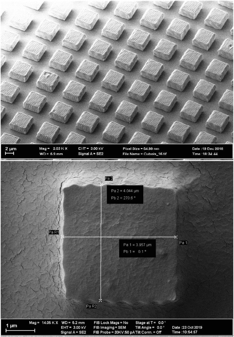
Fig. 1 shows electron microscopy images of the squares on the substrate. The surface of the squares shows a wavy structure (resembling a cracker) which is due to the printing process, where the laser focus is scanned across the sample in equidistant parallel lines. The path of the laser focus can be adjusted to make the surface more even, which comes at the expense of writing time. With the given laser intensity, beam velocity, and path we were able to write about four million squares within four days. The thickness of the squares of 2 μm is the best compromise for particles (i) being heavy enough in aqueous solution to sediment and form a monolayer, (ii) thin enough to not stand vertically on the 2 × 4 μm2 side, and (iii) minimizing the likelihood of overlapping particles. To detach the particles from the cover slide, a solution of 1%wt concentration of Pluronics-F127 and 0.3 M NaOH is used to wet the particles and cover slide for about 24 h. NaOH partially saponifies the PMMA-based photoresist, while the Pluronics-F127 helps wetting particles and cover slide for lift off, furthermore introducing sterical stabilization. Taking a 1 mL pipette of 1%wt Pluronics-F127 in distilled water, spreading and suctioning the solution repeatedly collects a fraction of squares from the glass plate into solution. Putting the solution in a 1 mL vessel, centrifuge 400g for 15 min, removing supernatant containing NaOH, and refilling with 1%wt Pluronics-F127 solution washes away the base while preventing aggregation of the colloids. After repeating the washing process about three times, 20% to 30% of the particles are left in about 1 mL solution. This colloidal solution is used to fill the sample cell for further experiments.
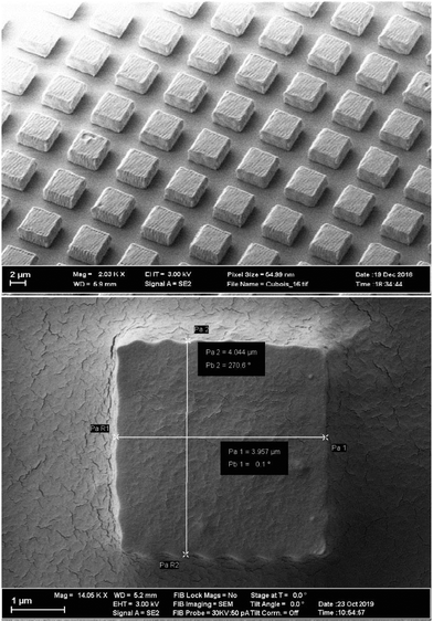 |
| | Fig. 1 Electron micrographs of squares written on a substrate after developing. The upper image serves as an overview to show the arrangement of the cubes after printing, and the lower images shows a single cube to measure its size, which is 4 ± 0.04 × 4 ± 0.04 μm2. | |
3 Formation of a 2D monolayer
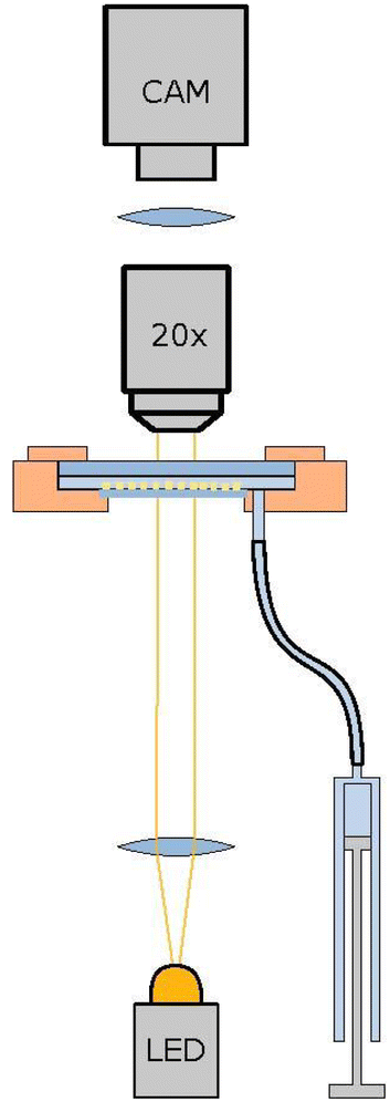
The colloidal solution is mounted in a sandwich geometry with a 80 μm thin cover slide in 2 mm aqueous solution, formed using a Teflon spacer ring, and sealed with a glass plate of 2 mm thickness at the top. The thin, lower cover slide is glued with UV-glue (Norland Optical Adhesive 81) for sealing, while the upper glass plate is sealed with a silicon rubber ring. The sandwich geometry is mounted in a copper block for thermal conductivity. The cell has a diameter of 20 mm and is illuminated from below with an LED illumination (HLV2-22SW-1220-3W from CSS Inc.) and monitored with an CCD-camera from above (Marlin F-145B from Allied Vision) using an 20× objective and optical tube (Opto Sonderbedarf GmbH).
The setup is similar to,38 with the exception being the lower interface water/air interface in hanging droplet geometry is a glass/air interface in the present work. The volume of the on average 2 mm thick water layer can be adjusted with a syringe (Hamilton SYR 1 mL 1001 TLL), driven by a micro-position system (Physical Instruments M-230.25). This way the thin lower glass plate can be curved from convex to concave with an amplitude up to 100 μm, where less than 10 μm suffice for the present application. The aqueous solution contains 1%wt Pluronics-F127 for sterical stabilization of the colloidal squares. Since the overlap volume of a flat surfaces is rather large, the steric stabilization works well and only a very small fraction of particles will be pinned on the solid glass surface. After mounting and sedimentation of the colloids, the 2D monolayer within the 20 mm diameter cell is very dilute to avoid particles to form a multilayer after sedimentation. During a period of several weeks, the curvature of the confining interface is increased to become convex in steps of about 0.5 μm and several days of waiting time. During this period, the particles sediment into the middle of the cell. Depending on the loss rate during writing, developing and washing the squares, a high concentrated colloidal monolayer in an area of about 5 mm to 6 mm in diameter can be achieved, with an area fraction between 0.5 to 0.76. Fig. 2 shows a sketch of the setup with the monolayer not to scale. The whole setup is mounted on a tripod with automated adjustable feet to keep the setup horizontal and the monolayer perpendicular to gravity with an accuracy of ±10−6 rad as in ref. 38.
 |
| | Fig. 2 Sketch of the setup. The colloidal monolayer (yellow squares, not to scale) sediments within a layer of 2 mm aqueous solution is sandwiched between two glass palates: The upper one is 2 mm thick and will not bend, while the curvature of the lower glass plate (thickness of 80 μm) can be adjusted easily with an amplitude up to 100 μm in the middle of the plate being 20 mm in diameter. This allows to change the volume of the aqueous solution by a micro-stage driven syringe. | |
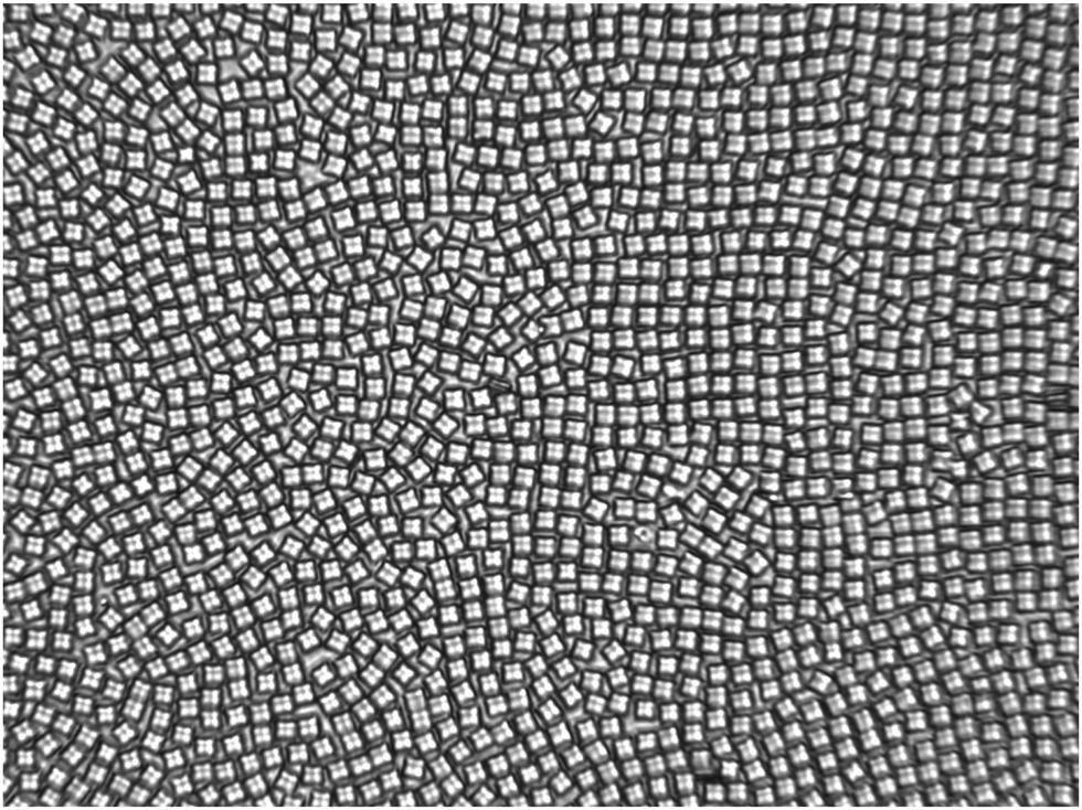
Fig. 3 shows a micro graph of the colloidal ensemble. The field of view is 210 × 157 μm2 and contains 1350 particles. Determined from Voronoi tesselation and neglecting particles less than 10 μm from the border, the packing fraction is 0.679. As will be shown later, the ensemble is in a tetratic phase at this density: particles are allowed to explore the plane by dislocation diffusion but the orientational degrees of freedom are restricted thus the bond order correlation is quasi-long ranged.
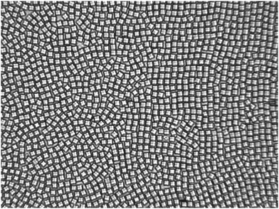 |
| | Fig. 3 Micrograph of the 2D ensemble of cubes on a solid substrate where the curvature of the substrate can be controlled. The field of view typically contains between 900 to 1500 particles in the field of view of 210 × 157 μm2 imaged on 1392 × 1040 pixel2. Here, the number of particles is 1350 and the ensemble of this example is in the tetratic phase (see below). | |
4 Image analysis
The detection of particles is a variant of ref. 38 using the tracking software of John Crocker and David Grier for the detection of particle positions,39 written in IDL (Interactive Data Language)‡. Summarized, the image is binarized in black and white binary large objects (BLOBS). BLOBS are detected via connected-component analysis to identify individual colloidal particles. The orientation of the cubes is detected based on the method for detecting the local bond order field19 as follows:40 defining BLOBi to be the set of pixel that belong to the ith blob, we average over the pixel positions ![[r with combining right harpoon above (vector)]](https://www.rsc.org/images/entities/i_char_0072_20d1.gif) p with the 2D coordinates taken as complex number = x + iy to calculate the center of mass
p with the 2D coordinates taken as complex number = x + iy to calculate the center of mass| | | = 〈p〉p∈BLOBi | (1) |
The center of mass of the BLOB serves as the particle position with sub-pixel resolution. The orientation ξ4,i of the ith squares is determined by looking at the pixel positions relative to the center of mass and analysing their distribution in four-fold space. The normalized orientation vector is| | ξ4,i = ![[small xi, Greek, tilde]](https://www.rsc.org/images/entities/i_char_e119.gif) 4,i/|4,i| 4,i/|4,i| | (2) |
with| | | 4,i = − 〈(p − i)4〉p∈BLOBi | (3) |
and measures the body-orientation of the square. Note, that the average of the four-fold pixel coordinates will point towards the corners of the cube, thus the negative value is taken so that ξ4 shows the direction of the flat side of the square.
To save hard disc space, we do not record individual pictures but only size of the BLOBS as well as positional and body-orientational data of all N particles in the field of view with a frame rate of 0.5 Hz for a duration of up to 36 hours at a given 2D density.
5 Results
The time-dependent particle positions are further processed to analyse the structure and phase of the colloidal ensemble. Here, we extract the structure factor and the bond - as well as body orientational correlation function to discriminate between isotropic fluid, tetratic and crystalline phase.
5.1 Structure factor
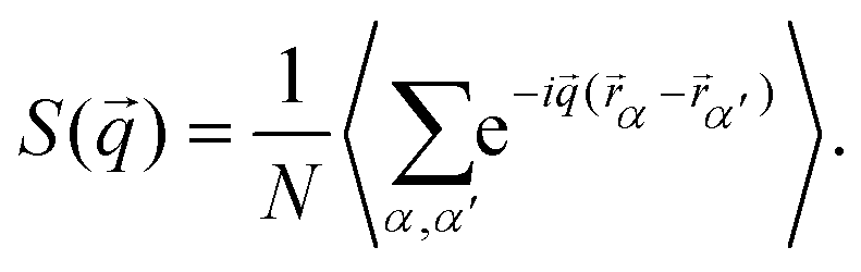
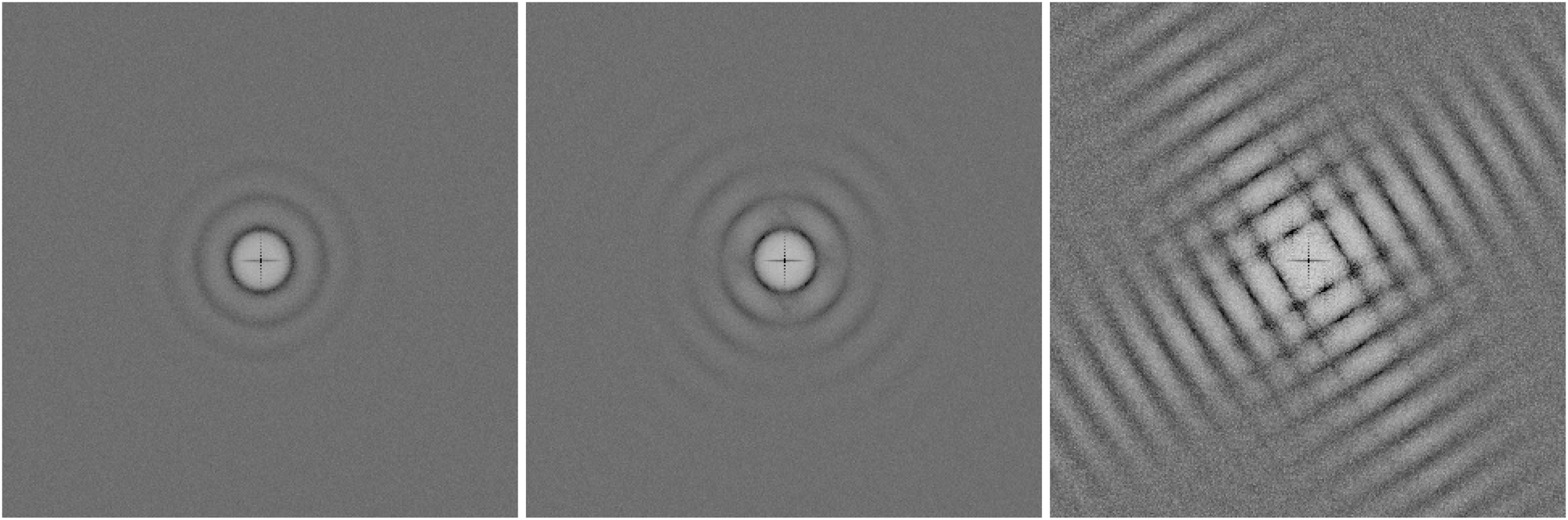
In close analogy to the search for the hexatic phase observed for isotropic particles19 and to distinguish the three phases and their symmetries, we plot the structure factor S(![[q with combining right harpoon above (vector)]](https://www.rsc.org/images/entities/i_char_0071_20d1.gif) ), calculated from the positional data for three different densities:
), calculated from the positional data for three different densities:| | 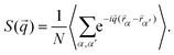 | (4) |
Here, α,α′ run over all N particles in the field of view, and a time average is taken over 74 configurations, as shown in Fig. 4. In the liquid phase, concentric rings appear having radii that can be connected to typical inter-particle distances. The tetratic phase is characterized by four segments of a ring which arise due to the quasi-long-range orientational order of the fourfold director. In the crystalline phase, Bragg peaks of finite width appear, reflecting the quasi-long-range character of the translational order in two dimensions due to Mermin–Wagner–Hohenberg fluctuations.41–43 To differentiate between the tetratic and crystalline phases, one could examine the azimuthal shape of the peaks. In the crystalline phase, the peaks are expected to follow a Lorentzian form, while in the tetratic phase, they should resemble the square root of a Lorentzian. However, previous studies have shown that this criterion is not particularly reliable numerically, at least when distinguishing the hexatic from the crystalline phase.44
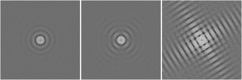 |
| | Fig. 4 Structure factor of the isotropic fluid shows concentric rings, reflecting very short ranged orientational order (left plot). The tetratic phase shows four segments of rings (middle plot) in the structure factor indicating quasi long ranged orientational order (middle plot). The crystalline phase shows a periodic square pattern (right plot). At the given densities, we never observed a rhombic crystal. | |
5.2 Bond- and body order correlations
A more robust criterion is the decay of the bond-order correlation function G4(), based on the four-fold local director field Ψ() given by the nearest neighbours. Here, the sum runs over the Nj next neighbors of the particle k at position and θjk is the angle between a fixed reference axis (e.g. the x-axis in a kartesian frame) and the bond of the particle k and its neighbor j:| |  | (5) |
For four neighbours arranged in about 90° with respect to each other around the center particle k, Ψ() adds up to a complex number with magnitude about unity. The phase of the complex number reflects the orientation of the square in four-folded space given by the neighbours according θjk. Topological defects with three or five nearest neighbours have on average 120° or 72° between the neighbours. In this case, the magnitude of Ψ() adds up to a complex number with magnitude close to zero in four-folded space. It follows that the orientational correlation between a defect and a four-folded particle is very small. The presence of defects also affects the correlation of four-folded particles at larger distances and is best measured with the four-folded correlation function G4().| | G4(r) = 〈Ψ()Ψ*(![[0 with combining right harpoon above (vector)]](https://www.rsc.org/images/entities/char_0030_20d1.gif) )〉, )〉, | (6) |
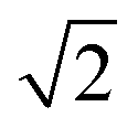
without any defects G4() does not decay at all, with dislocations it decays algebraically slow, and with disclinations it decays exponentially fast.3–5 Thus all three thermodynamic phases can be identified using the asymptotic behaviour of G4()
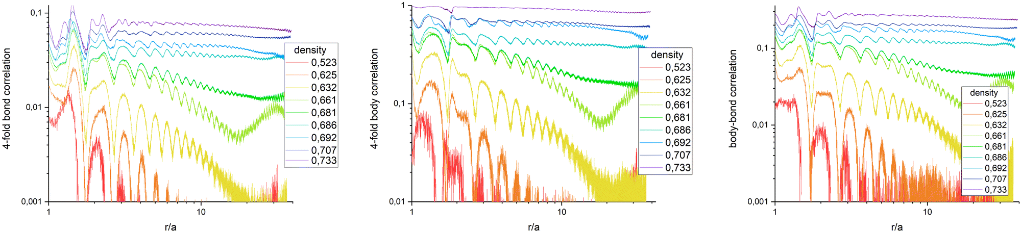
The average in eqn (6) is not only the ensemble average which is taken over all N(N − 1)/2 particle-pair distances for each configuration but also averaged over 720 statistically independent configurations. Fig. 5 (left) presents G4() in a log–log plot, to highlight the algebraic decay. Qualitatively, it behaves similar to colloidal ensembles with isotropic interaction, where the low-symmetry phase is hexagonal.19 At high particle densities (purple curve), G4() shows no decay, representing the square crystal phase. At medium densities (green curve), an algebraic decay is observed, corresponding to the tetratic phase. At low densities (orange/red curves), an exponential decay is evident, indicating the isotropic phase. G4() of a medium particle density (bright green curve) increases again with larger distances, explained by critical fluctuations: In the vicinity of the transition density, patches of symmetry-broken domains grow to the size of the field of view. Only for infinitely large systems, the ensemble would unambiguously be defined by its symmetry.
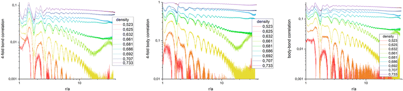 |
| | Fig. 5 Bond order correlation function G4(r) (left), body orientation correlation function B4(r) (middle), and bond-body cross correlation function G4B4(r) (right) in log–log plots to pic out the algebraic decay. No decoupling of bond and body correlation is observed, ruling out a rotator crystal at the given density. | |
Quantitative results differ from those of hexagonal crystals, where the amplitude of G6( = 0) ≈ 0.9 deep in the crystal phase, while G4( = 0) < 0.1. This discrepancy arises from the method used to determine nearest neighbors via Voronoi tessellation. In a perfect square crystal at zero temperature, the ideal network is tetravalent. However, at any nonzero temperature, thermal fluctuations cause tetravalent vertices to degenerate into two trivalent vertices. As a result, the Voronoi tessellation on average identifies six nearest neighbors for square crystals at finite temperatures. This explains why the normalization factor Nj in eqn (5) averages to six rather than four. Furthermore, while four neighbours appear under 90° and add up constructively in the four-fold director, two appear under multiples of 45° and contribute destructively. Both effects effectively reduce the amplitude of G4() when nearest neighbours are determined by Voronoi tessellation. For hexagonal networks Voronoi tessellation works best and determines neighbours without doubt. Since the distance of neighbours under 45° is about  longer, one can introduce a cut-off value for determining the four nearest neighbours, but this might interfere with correctly determining three- and five-fold dislocations. Another possibility is to weight the contribution of neighbours due to their part how they contribute to the circumference of the Voronoi-cell since the particles under multiples of 45° contribute much less. Furthermore, a 2D variant of determining neighbours in a parameter free way as introduced in ref. 45 can be used. Determining the most accurate and efficient method remains a topic of ongoing work.
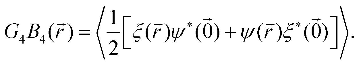
To check whether a rotator crystal shows up, where particles sit on lattice sites but are allowed to rotate relative to lattice directions, we have additionally investigated the body–body orientational correlation function. Based on eqn (2) which measures the body orientation along the edge of the square in vector of length unity, one can define the body correlation B4() in close analogy to eqn (6) as
Fig. 5 (middle) shows
B4(
) in a log–log plot. Beside the amplitude which is ≈1 for a crystal, the qualitative behavior is the same as for
G4(
). This includes the density
σ = 0.661 where critical behaviour is visible. The picture does not change taking the cross correlation of bond and body orientation as shown in
Fig. 5 (right) with
| |  | (8) |
For
= 0 it measures the autocorrelation of body- and bond-orientation for each particle, while for
≠ 0 it correlates two complex numbers of different particles and is therefore calculated in the symmetric version concerning particle exchange. Summarizing
Fig. 5 shows that bond-correlations, body-correlations, and the bond-body-cross correlations behave the very same for all densities under investigation. A rotator crystal is not observed in our ensemble with particles written by 3D photo lithography. With this technology, edges seem to be sharp enough to avoid rotation of particles in the crystals. This is in line with simulations of triangles, squares and hexagons where bond and body orientations are also strongly correlated.
31
6 Conclusions
Based on a two-dimensional crystal of mesoscopic particles with a square shape, the tetratic phase is experimentally validated in a thermal ensemble by analyzing the structure factor, S(q), and the four-fold bond-order correlation function, G4(r). The isotropic phase is characterized by isotropic rings in S(q) and an exponential decay of G4(r). The 2D square crystal is identified by a squared pattern in S(q) and a non-decaying G4(r). The tetratic phase is marked by four segments of rings in S(q) and an algebraic decay of G4(r) as presented in this work. Analysis of the structure factor revealed no evidence of a rhombic phase across all densities investigated. Furthermore, examination of body-orientational correlations and bond-body cross-correlations showed no indication of a rotator crystal phase. Further investigation will be pinning down the exact transition densities - there is still some variance reported in simulations - and measuring elasticity close to the transitions.
Author contributions
R. L.: data curation, formal analysis, software, investigation. L. S.: data curation, formal analysis, software, investigation. P. K. formal analysis, software, project administration, supervision, writing.
Data availability
The data-sets generated and analysed for the current study will be made available for the final version of the manuscript on a public data-repository.
Conflicts of interest
There are no conflicts of interest to declare.
Acknowledgements
L. S. acknowledges financial support from the Department of Physics, University of Konstanz. P. K. acknowledges support from the German Research Foundation (DFG) project number 453041792 (Heisenberg funding) and project number 268730352 (SFB-1214 project B2). We acknowledge the Nanostructure Laboratory at University of Konstanz and especially the lab manager Matthias Hagner. All authors are grateful about always fruitful discussions with Georg Maret.
Notes and references
- J. M. Kosterlitz and D. J. Thouless, J. Phys. C: Solid State Phys., 1972, 5, L124 CrossRef CAS.
- J. M. Kosterlitz and D. J. Thouless, J. Phys. C: Solid State Phys., 1973, 6, 1181 CrossRef CAS.
- D. R. Nelson and J. M. Kosterlitz, Phys. Rev. Lett., 1977, 39, 1201–1205 CrossRef CAS.
- B. I. Halperin and D. R. Nelson, Phys. Rev. Lett., 1978, 41, 121–124 CrossRef CAS.
- D. R. Nelson and B. I. Halperin, Phys. Rev. B, 1979, 19, 2457–2484 CrossRef CAS.
- A. P. Young, Phys. Rev. B, 1979, 19, 1855–1866 CrossRef CAS.
- A. Jaster, Phys. Rev. E: Stat. Phys., Plasmas, Fluids, Relat. Interdiscip. Top., 1999, 59, 2594–2602 CrossRef CAS.
- C. H. Mak, Phys. Rev. E: Stat., Nonlinear, Soft Matter Phys., 2006, 73, 065104 CrossRef CAS PubMed.
- S. Z. Lin, B. Zheng and S. Trimper, Phys. Rev. E: Stat., Nonlinear, Soft Matter Phys., 2006, 73, 066106 CrossRef CAS PubMed.
- C. A. Murray and D. H. Van Winkle, Phys. Rev. Lett., 1987, 58, 1200–1203 CrossRef CAS PubMed.
- Y. Tang, A. J. Armstrong, R. C. Mockler and W. J. Osullivan, Phys. Rev. Lett., 1989, 62, 2401–2404 CrossRef CAS PubMed.
- R. E. Kusner, J. A. Mann, J. Kerins and A. J. Dahm, Phys. Rev. Lett., 1994, 73, 3113–3116 CrossRef CAS PubMed.
- R. E. Kusner, J. A. Mann and A. J. Dahm, Phys. Rev. B: Condens. Matter Mater. Phys., 1995, 51, 5746–5759 CrossRef CAS PubMed.
- A. H. Marcus and S. A. Rice, Phys. Rev. Lett., 1996, 77, 2577–2580 CrossRef CAS PubMed.
- K. Zahn, R. Lenke and G. Maret, Phys. Rev. Lett., 1999, 82, 2721–2724 CrossRef CAS.
- K. Zahn and G. Maret, Phys. Rev. Lett., 2000, 85, 3656–3659 CrossRef CAS PubMed.
- C. Eisenmann, U. Gasser, P. Keim, G. Maret and H. H. von Grünberg, Phys. Rev. Lett., 2005, 95, 185502 CrossRef CAS PubMed.
- J. Zanghellini, P. Keim and H. H. V. Grünberg, J. Phys.:Condens. Matter, 2005, 17, S3579 CrossRef CAS.
- P. Keim, G. Maret and H. H. von Grünberg, Phys. Rev. E: Stat., Nonlinear, Soft Matter Phys., 2007, 75, 031402 CrossRef CAS PubMed.
- U. Gasser, C. Eisenmann, G. Maret and P. Keim, ChemPhysChem, 2010, 11, 963–970 CrossRef CAS PubMed.
- A. L. Thorneywork, J. L. Abbott, D. G. A. L. Aarts and R. P. A. Dullens, Phys. Rev. Lett., 2017, 118, 158001 CrossRef PubMed.
- A. L. Thorneywork, J. L. Abbott, D. G. A. L. Aarts, P. Keim and R. P. A. Dullens, J. Phys.: Condens. Matter, 2018, 30, 104003 CrossRef PubMed.
- E. P. Bernard and W. Krauth, Phys. Rev. Lett., 2011, 107, 155704 CrossRef PubMed.
- M. Engel, J. A. Anderson, S. C. Glotzer, M. Isobe, E. P. Bernard and W. Krauth, Phys. Rev. E: Stat., Nonlinear, Soft Matter Phys., 2013, 87, 042134 CrossRef PubMed.
- S. C. Kapfer and W. Krauth, Phys. Rev. Lett., 2015, 114, 035702 CrossRef PubMed.
- C. Eisenmann, U. Gasser, P. Keim and G. Maret, Phys. Rev. Lett., 2004, 93, 105702 CrossRef CAS PubMed.
- C. Eisenmann, P. Keim, U. Gasser and G. Maret, J. Phys.: Condens. Matter, 2004, 16, 4095–4102 CrossRef.
- V. A. Froltsov, C. N. Likos, H. Löwen, C. Eisenmann, U. Gasser, P. Keim and G. Maret, Phys. Rev. E: Stat., Nonlinear, Soft Matter Phys., 2005, 71, 031404 CrossRef CAS PubMed.
- K. Wojciechowski and D. Frenkel, CMST, 2004, 10, 235–255 CrossRef.
- F. Smallenburg, L. Filion, M. Marechal and M. Dijkstra, Proc. Natl. Acad. Sci. U. S. A., 2012, 109, 17886–17890 CrossRef CAS PubMed.
- J. A. Anderson, J. Antonaglia, J. A. Millan, M. Engel and S. C. Glotzer, Phys. Rev. X, 2017, 7, 021001 Search PubMed.
- L. Walsh and N. Menon, J. Stat. Mech.: Theory Exp., 2016, 2016, 083302 CrossRef.
- K. Zhao, R. Bruinsma and T. G. Mason, Proc. Natl. Acad. Sci. U. S. A., 2011, 108, 2684–2687 CrossRef CAS PubMed.
- C. Avendano and F. A. Escobedo, Soft Matter, 2012, 8, 4675–4681 RSC.
- P. Gurin, S. Varga and G. Odriozola, Phys. Rev. E, 2020, 102, 062603 CrossRef CAS PubMed.
- A. Donev, J. Burton, F. H. Stillinger and S. Torquato, Phys. Rev. B: Condens. Matter Mater. Phys., 2006, 73, 054109 CrossRef.
-
D. Dertli and T. Speck, In pursuit of the tetratic phase in hard rectangles, arXiv, 2024, preprint, arXiv:2408.06889 DOI:10.48550/arXiv.2408.06889, accepted at Physical Review Research, 2025.
- F. Ebert, P. Dillmann, G. Maret and P. Keim, Rev. Sci. Inst., 2009, 80, 083902 CrossRef CAS PubMed.
- J. C. Crocker and D. G. Grier, J. Colloid Interface Sci., 1996, 179, 298–310 CrossRef CAS.
-
R. Löffler, Master thesis, University of Konstanz, 2018.
- N. D. Mermin and H. Wagner, Phys. Rev. Lett., 1966, 17, 1133 CrossRef CAS.
- P. Hohenberg, Phys. Rev., 1967, 158, 383 CrossRef CAS.
- N. D. Mermin, Phys. Rev., 1968, 176, 250 CrossRef.
- P. Dillmann, G. Maret and P. Keim, J. Phys.: Condens. Matter, 2012, 24, 464118 CrossRef PubMed.
- J. A. v Meel, L. Filion, C. Valeriani and D. Frenkel, J. Chem. Phys., 2012, 136, 234107 CrossRef PubMed.
Footnotes |
| † Toptica FemtoFiber pro, center wavelength 780 nm, average power 180 mW. |
| ‡ https://www.nv5geospatialsoftware.com/Products/IDL |
|
| This journal is © The Royal Society of Chemistry 2025 |
Click here to see how this site uses Cookies. View our privacy policy here. 
 Open Access Article
 This Open Access Article is licensed under a
  *bcd
*bcd

 longer, one can introduce a cut-off value for determining the four nearest neighbours, but this might interfere with correctly determining three- and five-fold dislocations. Another possibility is to weight the contribution of neighbours due to their part how they contribute to the circumference of the Voronoi-cell since the particles under multiples of 45° contribute much less. Furthermore, a 2D variant of determining neighbours in a parameter free way as introduced in ref. 45 can be used. Determining the most accurate and efficient method remains a topic of ongoing work.