The critical role of heterogeneous catalysis in lignocellulosic biomass conversion
Yu-Chuan
Lin
and
George W.
Huber
*
Department of Chemical Engineering, University of Massachusetts, 159 Goessmann Laboratory, 686 North Pleasant St., Amherst, MA, USA. E-mail: huber@ecs.umass.edu; Fax: (+1) 413-545-1647
First published on 20th November 2008
Abstract
Lignocellulosic biofuels have a tremendous potential to reduce problems caused by our dependence on fossil fuels. The current roadblock with biofuels is the lack of economical conversion technologies. Heterogeneous catalysis offers immense potential in helping to make lignocellulosic biofuels a commercial reality. In this article we discuss the central role of heterogeneous catalysis in biomass conversion. We review the science of catalysis and the different routes to make biofuels. During the last several decades multiple new spectroscopic, theoretical, and synthesis tools are available that allow us to study catalysis at a molecular level. These new tools will allow us to rapidly develop new catalytic processes for the production of cost-efficient lignocellulosic biofuels.
 Yu-Chuan Lin Yu-Chuan Lin | Yu-Chuan Lin was born in Taipei, Taiwan. He received his BS (2000) and MS (2002) degrees in Chemical Engineering from National Cheng Kung University (Taiwan), with Hung-Shan Weng as his MS advisor. He obtained his PhD in Chemical Engineering from Kansas State University (2006) under the guidance of Keith L. Hohn; his doctoral study focused on catalytic partial oxidation. Besides experimental works, Yu-Chuan collaborated with L. T. Fan in catalytic pathway identifcations via a newly developed graph-theoretic method (P-graphs). He joined the group of George W. Huber at Department of Chemical Engineering, University of Massachusetts-Amherst as a postdoctoral researcher in 2008. The focus of his current research is lignocellulosic biomass conversion through novel catalytic approaches. |
 George W. Huber George W. Huber | George W. Huber is the John and Elizabeth Armstrong Professional Development Professor of Chemical Engineering at University of Massachusetts-Amherst. His research focus is on Breaking the Chemical and Engineering Barriers to Lignocellulosic Biofuels. His discovery of Raney–NiSn catalyst for hydrogen production from biomass-derived oxygenates was named as one of top 50 technology breakthroughs of 2003 by Scientific America. George is currently working with numerous governmental and industrial institutions to help make cellulosic biofuels a reality. George did a post-doctoral stay with Avelino Corma at the Technical Chemical Institute at the Polytechnical University of Valencia, Spain (UPV-CSIC) where he studied biofuels production using petroleum refining technologies. He obtained his PhD in Chemical Engineering from University of Wisconsin-Madison (2005) where he helped develop aqueous-phase catalytic processes for biofuels production under the guidance of James A. Dumesic. He obtained his BS (1999) and MS (2000) degrees from Brigham Young University. |
Broader contextHeterogeneous catalysis possesses immense potential to transform lignocellulosic biomass into liquid fuels and chemicals. This article reviews the existing routes in biomass conversion that use heterogeneous catalysts and discusses the role of catalytic science. Over the last 20 years new cutting-edge experimental, synthetic and theoretical techniques have been developed that can now be applied to the conversion of biomass into fuels and chemicals. These cross-cutting tools will allow us to rapidly develop new catalysts and catalytic processes for the conversion of biomass into fuels and chemicals. |
1. Introduction
Concerns with increasing prices of petroleum oil, combined with environmental and national security problems are causing our society to search for new, renewable sources of liquid transportation fuels. In this respect, biomass is the only sustainable source of carbon that can be used to make renewable fuels and chemicals.1–3Biomass feedstocks can be classified into three general groups: lignocellulosics or woody biomass (the non-edible portion of biomass, e.g., bagasse, corn stover, grasses, wood, etc.), amorphous sugars (e.g., starch, glucose, etc.), and triglycerides (e.g., vegetable oil). The cheapest, most abundant, and fastest growing form of terrestrial biomass is lignocellulosic biomass, which is composed of three primary building blocks: cellulose, hemicellulose and lignin.1 While lignocellulosic biomass is a desirable feedstock, it is not yet economically viable to convert it into liquid transportation fuels. It has been stated that “the central and surmountable impediment to more widespread application of biocommodity engineering (or biorefining) is the general absence of low-cost processing technology.”4 There are a number of engineering and scientific challenges that must be overcome for lignocellulosic biofuels to be economically competitive with fossil-based fuels. In this respect the field of heterogeneous catalysis offers tremendous potential in breaking the engineering and scientific barriers to make economical feasible routes to lignocellulosic biofuels.5 Heterogeneous catalysts are the most encountered form of catalysts used in the petroleum and chemical industries. The purpose of this review is to discuss the critical role of heterogeneous catalysis in the conversion of lignocellulosic biomass into liquid fuels and chemicals.
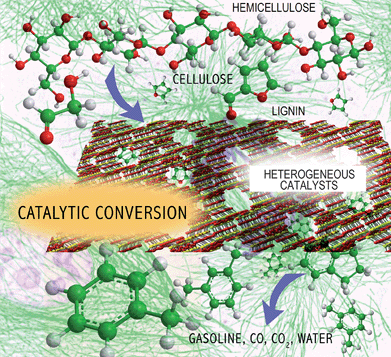
The overall challenge with biomass conversion is how to efficiently remove oxygen from the biomass feedstocks and produce a molecule that has a high energy density and good combustion properties as shown in Fig. 1. In the conversion processes, oxygen is removed as a combination of CO2 and H2O. The first step in this process is the deconstruction of the solid lignocellulosics into smaller hydrophilic products. During the second conversion step more oxygen is removed from the hydrophilic materials and the biomass is converted into the fuel product, CO2 and H2O. Biomass conversion hence involves chemistries occurring in multiple phases. The optimal fuel product is most likely to be one that fits into existing infrastructure and has similar properties to gasoline, diesel, and jet fuel. The ideal conversion process also produces the highest yield of biofuels as inexpensively as possible.
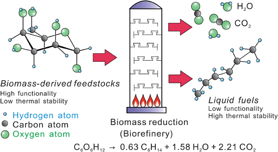 | ||
| Fig. 1 Challenge of biomass conversion. | ||
There are currently several routes being studied to synthesize biofuels as shown in Fig. 2. Three general routes are employed for lignocellulosic biomass deconstruction, including: (1) gasification to syngas (CO and H2) at high temperatures, (2) deconstruction by selective thermal processing at intermediate temperatures (typically by fast pyrolysis or liquefaction), and (3) deconstruction into monomer products at low temperatures. Once the biomass is deconstructed then many different conversion schemes can be used. It is a difficult task to analyze which is the best scheme for a particular type of biomass.
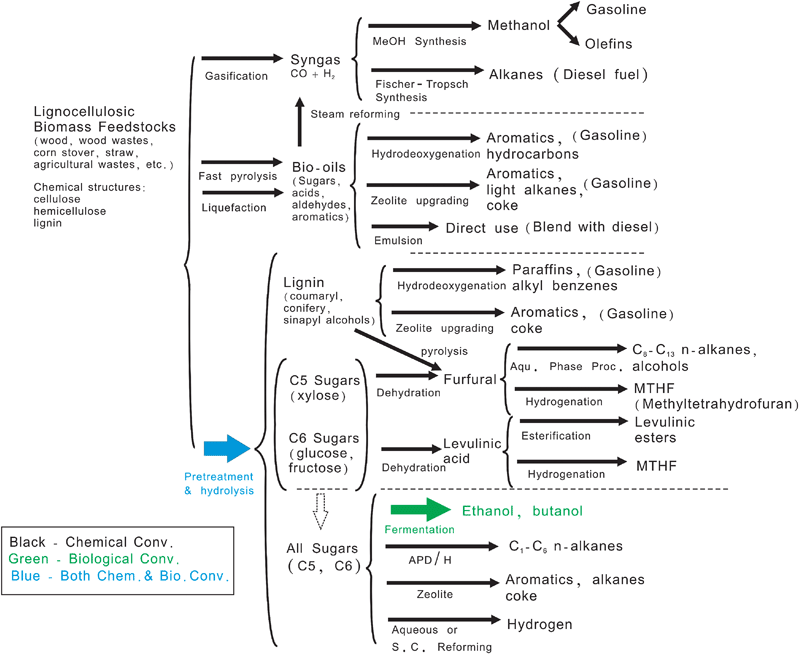 | ||
| Fig. 2 Known routes for production of biofuels from lignocellulosic biomass. Adapted from Huber et al.1 | ||
The routes that use chemical (primarily heterogeneous) catalysts are shown in black; biological conversion are shown in green; while the combination of chemical and biological are shown in blue in Fig. 2. As observed most of the routes to produce biofuels use heterogeneous catalysts.6–8 This is similar to today's scenario of the petroleum refinery where approximately 90% of petroleum and chemical processes use heterogeneous catalysts.9,10 It is highly likely that the future biorefinery, a processing plant for converting waste and virgin biomass feedstocks to energy, fuel, and other products,11 will use heterogeneous catalysis.
In this review we discuss the cross-cutting areas of heterogeneous catalysis and its potential in the biorefinery. We will first introduce the science of catalysis. Few fields are as multi-disciplinary as heterogeneous catalysis which includes: chemical engineering, theoretical chemistry, synthetic chemistry, physical chemistry, surface science, and solid state physics. We will then review some current approaches of heterogeneous catalysis in biomass conversion. In the past 10–20 years many new tools have been developed which can now be applied to the development of new generations of catalysts. We conclude by discussing some of these new tools and how they can have an impact on developing economical processes for the conversion of our renewable lignocellulosic biomass resources to fuels and chemicals.
2. Basics of catalysis
The basic definition of a catalyst, proposed by Ostwald in 1894, is a substance that accelerates the rate of chemical reaction without itself being consumed.12,13 It does not vary the thermodynamic equilibrium of reaction. Another definition is that a catalyst is a substrate which transforms reactants into products, through an uninterrupted and repeated cycle of elementary steps in which the catalyst participates while being regenerated to its original form at the end of each cycle during its lifetime.14,15 A catalyst influences not only the reaction rate, but also the distribution of products.8 Detailed description about the concept of catalysis can be found elsewhere.15–18Traditionally, catalytic systems are categorized as homogeneous, heterogeneous, and enzymatic, reflecting the ascending hierarchy of complexity.13 This classification may have to be revised as multiple research groups are blurring the borders between homogeneous, heterogeneous, and enzymatic catalyses.19 Homogeneous catalyses are those where the catalyst is in the same phase (either liquid or gas) as the reactants and products. Heterogeneous catalysts are those where the catalyst is in a separate phase than the reactants. A heterogeneous catalyst is typically a solid material and the catalytic reaction generally occurs on a solid surface. Enzymatic catalysts are a subset of homogeneous catalysis where the catalysis occurs by biological units.
The primary advantage of heterogeneous catalysts is that they are in a solid phase and they can easily be separated and recycled from the gas and/or liquid reactants and products.8,15 Thus, the catalyst can be prepared and lasts several years before it needs to be replaced. In comparision, it is difficult to separate and recycle homogeneous catalysts. Another merit of heterogeneous catalysts is their stability to severe reaction environments; some can withstand temperature as high as 1600 K and pressure up to 350 atm.16 In comparison biological catalysts can only be used at low temperature environment (less than 330 K). In general, the higher the reaction temperature the faster the reaction and the smaller the reactor size. Furthermore, heterogeneous catalysts are non-corrosive in standard reactor units; unlike most of homogeneous catalysts, e.g., sulfuric acid, needs to be handled in corrosion-proof facilities.8
2.1 Morphology of a heterogeneous catalyst
A heterogeneous catalyst is typically a porous material with high surface area. The reactions take place on the surface of the catalyst and it is typically desirable to maximize the surface area of the catalyst. When a catalyst involves a precious metal component (e.g., Pt, Rhetc.), it is dispersed on a high surface area material (called support) so that the reactant-exposed metal atoms can be maximized.Fig. 3 shows an example of Pt/Al2O3catalyst where the Pt particles present as small crystallites on Al2O3 support. Most of the supports have an extremely high surface area, for example, silica–alumina has a BET surface area of 200–500 m2 g−1.
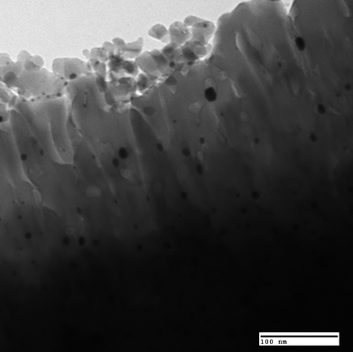 | ||
| Fig. 3 Transmission electron micrograph of Pt/Al2O3catalyst. Photo courtesy of Keith L. Hohn. | ||
2.2 Principles of heterogeneous catalysis
One of the key challenges with heterogeneous catalysis is to try and identify the active catalytic surface. Various surface sites exist on the catalytic surface, such as edges, kinks, terraces, and vacancies, which all have different reactivities.10 The heterogeneity becomes further complicated when anchoring other species around the active sites. Moreover, inherent impurities of the catalyst and time-on-stream reaction processing can alter the surface.15 All of them provide different catalytic environments. These observation form the basis that a catalytic reaction takes place merely on specific locations of the catalytic surface, termed active sites or active centers.20 Characterization techniques originated from this concept, such as selective chemisorption of gases (e.g., CO, H2, C2H4etc.), which are still broadly used today.15,17 Turnover frequency (TOF), the most important way to evaluate catalytic activity, is defined as the number of molecules that react per active site per unit time (in units of reciprocal time).17,21TOFs also provide a simple way to compare different catalysts.Another concept proposed by Boudart divides heterogeneous catalysis into “structure-sensitive” and “structure-insensitive” reactions.22 Structure-sensitive reactions are those whose rates change as the particles or morphologies of active sites vary. Conversely, the activity of a structure-insensitive reaction is not a function of particle size of the catalyst.18
2.3 How a heterogeneous catalyst functions?
Heterogeneous catalysis involves seven different steps as shown in Fig. 4. The first step involves diffusion of the reactants from a bulk fluid to the catalyst particle. Step 2 is the diffusion of the reactant through the catalyst intraparticle pores. Steps 3, 4 and 5 are the adsorption of the reactant onto the catalytic surface, the reaction of the reactant on the catalytic surface and the desorption of the products. The products must then diffuse through the catalyst intraparticle pores (Step 6) followed by diffusion into the bulk fluid (Step 7). Any of these steps can be the limiting depending on the catalyst design, the reactor setup, and the reaction condition.10,23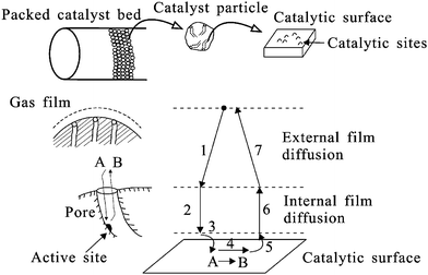 | ||
| Fig. 4 Steps in heterogeneous catalysis reaction A → B in a porous supported catalyst. Adapted from Bartholomew and Farrauto.10 | ||
A successful catalyst is generally underpinned by three factors: activity, selectivity, and stability. Activity refers to the rate of the reaction.17 Selectivity is defined as the percentage of the spent reactant that forms the desired product.17 Stability is determined by how quickly the catalytic activity declines, and determines how often the catalyst has to be replaced.10
The porosity, or pore shape of the catalyst, can also have a great effect on catalytic properties.24 Two chemically identical catalysts having different porosities can have significant differences in reactivity.25 Some of the precise architectures can distinguish reactants and products through its space restriction, functioning as “shape-selective” catalysis. Zeolites are one of the most common shape-selective catalysts, and are one of the success stories in the petrochemical industry.5 They are crystalline aluminosilicate (with trace metal ions) molecular sieves with open porous structures and ion exchange capabilities.26 Zeolites can be employed in petroleum refining, selective adsorbing, drying, separation and purification of gases and liquids, as well as ion exchange and water treatment.10 Today, including the aluminophosphate (ALPO) molecular sieves, 167 types of zeolites are recognized,27,28 some of them have already shown their potential in conversion of biomass.29–31
As mentioned previously, an ideal catalyst functions cyclically in the process. In real terms, however, its activity or selectivity decays over a period of time – known as deactivation. Causes of deactivation include: poisoning, fouling, degrading, sintering, active phase leaching, attrition, and crushing.10 Sometimes the catalysts can be rapidly regenerated. For example, when conducting cracking of hydrocarbons, carbonaceous deposits (coke) rapidly deactivates the catalyst.32 Nevertheless, the catalyst can be regenerated by oxidation of the coke.10,33 The design of durable and stable catalysts still remains a great challenge, especially when converting heavy or complex reactants, such as coal, shale oil, and biomass.
3. Catalytic processing in biomass conversion
Although catalysis has established momentous achievements in the petrochemical industry, its development in biorefinery applications is nascent. Fig. 5 shows a bibliometric analysis done on catalysis papers that are related to biomass conversion.34 As can be observed, only 1 out of every 400 catalysis papers is related to biomass conversion from 1996–2005. In 2004 only 30 papers were published on catalysis and biomass conversion. However, as can be seen from Fig. 5, this field is growing exponentially. The reason why catalysis has not been used for biomass conversion probably has to do with the price difference between crude oils and biomass. As the cost of biomass decreases relative to crude oils it is highly likely that this field will grow continuously.35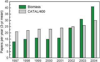 | ||
| Fig. 5 Catalysis papers (divided by 400) compared with catalysis papers relevant to biomass as a source of energy (biomass), 1996–2005, three-year running means. Adapted from Huber.34 | ||
The processing of biomass feedstocks occurs at different reaction conditions (i.e. temperature and pressure) than processing of petroleum feedstocks. Fig. 6 illustrates the processing conditions for these two types of reactants. Petroleum-derived substrates are mainly treated at temperatures higher than 673 K in vapor phase. In contrast, biomass-based compounds have a significantly lower thermal stability than petroleum-derived feedstocks which leads to the need to process them in the liquid phase (or very carefully in the gas phase). Accordingly, liquid phase catalytic processing at moderate temperature has been shown to be advantageous in processing of biomass.36 Reactions such as hydrolysis, dehydration, isomerization, oxidation, aldol condensation, and hydrogenation are frequently conducted under this environment.2 The aqueous phase can also be used to design new types of catalysts that are not suitable for gas phase conversion.
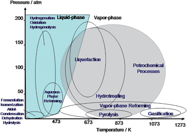 | ||
| Fig. 6 Diagram of approximate reaction conditions for the catalytic processing of petroleum versus biomass-derived carbohydrates. Adapted from Chheda et al.2 | ||
As discussed above lignocellulosic biomass conversion involves many different routes.1 In the following sections we will discuss the role of catalysis in some of these routes.
3.1 Syngas conversion
Syngas, also called synthesis gas, is a mixture of carbon monoxide and hydrogen which can be produced through the gasification of biomass.11 This is the most technically developed area of biofuels and has already been commercialized. Companies such as Choren,37 Coskata,38 and Range Fuels39etc., adopted this technique as their front-end process of biomass-derived alcohols and alkanes preparations.Biomass gasification can be done by co-feeding the biomass with fossil fuels (e.g., coal or natural gas).1 Syngas can be converted to electric power, hydrogen, steam, and numerous fuels or chemicals.40 There are two well known processes for syngas conversion: methanol synthesis41 and Fischer–Tropsch synthesis (FTS).42Fig. 7 shows Sasol Oryx FTS plant in Qatar. Its capacity to produce gasoline and diesel fuels is ca. 34![[thin space (1/6-em)]](https://www.rsc.org/images/entities/char_2009.gif) 000 barrels per day. The capital cost for this plant, which began operation in late 2006, was roughly $1.0–1.5 billion or $30,000 per barrel per day. By mid-2007, however, escalation of worldwide material and construction costs had driven capital costs upward by 2–3 folds. Thus, the capital cost for a plant (100
000 barrels per day. The capital cost for this plant, which began operation in late 2006, was roughly $1.0–1.5 billion or $30,000 per barrel per day. By mid-2007, however, escalation of worldwide material and construction costs had driven capital costs upward by 2–3 folds. Thus, the capital cost for a plant (100![[thin space (1/6-em)]](https://www.rsc.org/images/entities/char_2009.gif) 000 barrels per day) constructed in 2007 could exceed $10 billion!7
000 barrels per day) constructed in 2007 could exceed $10 billion!7
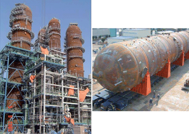 | ||
| Fig. 7 Sasol Oryx plant for Fischer–Tropsch synthesis in Qatar. Photo courtesy of Calvin H. Bartholomew. | ||
Four main processing units are needed for biomass conversion via syngas routes: a biomass gasifier, a gas clean-up unit, a water–gas shift (WGS) reactor in certain cases, and finally a syngas converter.7 The gasification unit converts the biomass at high temperature (600–900 °C) with oxidants (e.g., oxygen or steam). Syngas is the major product from the gasifier, accompanied by impurities such as tars, ammonia, hydrogen sulfide, and particulates.43 These impurities can have an adverse effect on downstream processing, hence, they must be removed by different chemical and physical treatments.7 Although clean-up has been intensively studied, additional research is needed.7,43 An example to deal with this difficulty is through catalyst design. By replacing commercially available Ni-based catalysts to perovskite-structural La–Ni–Fe catalysts can dramatically decrease tars with enhanced stability. This has been successfully applied on conditioning the outlet gas of a gasifier with almond shells, a lignocellulosic material, as the feed.44 A water–gas shift reactor is used before the syngas conversion step, to increase H2/CO ratio to the required stoichiometry for production of alcohols or alkanes.45 The last step, syngas conversion, is through CO hydrogenation. Depending on the catalysts and reaction conditions, numerous chemicals can be fabricated, including synthetic natural gas, alcohols, gasoline, diesel fuel, jet fuel, and heating fuel.7
One of the key opportunities for future cost reduction is process intensification, which focuses on combining process steps to decrease capital costs. One example of this is being developed by Lanny Schmidt, who showed that rhodium–cerium catalysts introduced into the gasifier can significantly reduce the amount of tars in the outlet stream.46 This design offers promise in syngas process intensification.
3.2 Selective thermal processing
Selective thermal processing of biomass is the thermal decomposition of biomass into liquid products usually called bio-oils. Bio-oils are currently the cheapest form of liquid fuels that can be made from lignocellulosic biomass. In the 1970s, researchers found the reaction conditions that maximize liquid bio-oil yields.47 There are two major routes to produce bio-oils – fast pyrolysis and liquefaction.Bio-oils are dark brown with a smoky odor and composed of polar organics (ca. 75–80 wt%) and water (ca. 20–25 wt%).48 The organic phase consists of water soluble and insoluble moieties. The water soluble phase has a high oxygen content, originating from cellulose and hemicellulose fractions of biomass. The water insoluble phase derives from the lignin fraction of biomass, and has lower oxygen content and high viscosity.7 Crude bio-oils have multiple shortcomings, such as low heating value (16–19 MJ Kg−1; less than half that of petroleum-derived fuels), strong corrosiveness (pH of 2–3), high viscosity (35–1000 cP at 40 °C), and poor chemical stability (viscosity and phase change with time).48 Despite these deficiencies, bio-oils can be transformed into transportation fuels, chemicals or even hydrogen by downstream upgrading.49 Several routes are available for bio-oils upgrading, including hydrotreating, zeolite upgrading, bio-oil mixtures, and steam reforming.1 For instance, both promoted non-precious (Ni) and noble metal (Pd, Pt, and Rh) catalysts are active in steam reforming of bio-oils to hydrogen.50 In hydrotreating of bio-oils, catalysts were first used that were used in hydrotreating of crude oil such as sulfided Ni/Mo catalysts. These catalysts showed that hydrotreating of bio-oils was possible, nevertheless, there were problems with poor yields. Now new generation catalysts are being used for hydrotreating of bio-oils that are specifically designed for conversion of biomass-derived feedstocks.51
Fast pyrolysis is the thermal depolymerization process in which biomass is rapidly heated in the absence of oxygen with short residence time at atmospheric pressure. Depending on the reaction condition, reactor design, and biomass feedstocks, the distribution of products varies in the gas, liquid, and solid phases.48 The keys to maximize yields of bio-oils are: rapid heating, high heat transfer rate, short residence time, moderate reaction temperature (ca. 500 °C), and rapid cooling of pyrolysis vapors.7 An advantage of fast pyrolysis is that it is economical for use on a small scale (i.e. 50–100 tons-biomass per day). Fig. 8 shows a portable fast pyrolysis reactor for liquid fuels production. This portable unit can easily access the biomass source, which significantly reduces costs in transportation of feedstocks.7,52
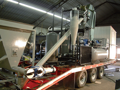 | ||
| Fig. 8 Portable fast pyrolysis plant. Photo courtesy of Phillip C. Badger. | ||
Liquefaction is carried out in a solvent, mostly water,53 under relatively lower temperature (300–400 °C) and higher pressure (120–200 atm) than fast pyrolysis. Catalysts are usually employed in the process.47,54 One of the attractive merits for liquefaction is directly processing of wet biomass without pre-drying.7 Moreover, the bio-oils produced through liquefaction have lower oxygen content than fast pyrolysis: decarboxylation prevails. This yields more favorable C/H ratio, water-insoluble bio-oils than those generated via fast pyrolysis. Nevertheless, the high pressure of reaction condition increases the capital costs of bio-oils derived from liquefaction.55 An up-to-date review about biomass conversion through liquefaction has been published by Tester and collaborators.56 The detailed summary of used heterogeneous catalysts and reaction platforms has been reported therein.
One promising option for selective thermal processing of biomass is to incorporate heterogeneous catalysis into the fast pyrolysis process, thus producing targeted fuels and chemicals.31,57Fig. 9 illustrates this conceptual scheme. Previous research in this area was not very successful because primarily large amounts of coke was produced. Recent research in the Huber group has shown that catalytic fast pyrolysis can be used to produce targeted aromatics in high yields with zeolite-based catalysts.31 These high yields were achieved due to proper reaction conditions (heating rates, temperatures, catalyst to feed ratios), and proper catalyst selection. This promising route appears to transform the area of selective thermal processing from making low value bio-oils to being able to selectively produce higher value targeted fuels.
Another approach in selective thermal processing called “biomass catalytic cracking” is being developed by KiOR, a private venture.58 The core of this approach is to use catalytic chemistry to open up the woody structure of biomass at lower temperatures than traditional thermal conversion. This approach can improve the yield of the bio-oils and also can reduce the cost of bio-oils preparation.7,58 KiOR's target is to make a bio-crude which can be upgraded in a standard petroleum refinery.
3.3 Liquid phase catalytic processing
Compared to petroleum feedstocks, biomass feedstocks have lower thermal stability. In other words, it is difficult to process them in the gas phase. This motivated Dumesic and collaborators to create liquid phase processing approaches to convert biomass-derived feedstocks to a range of fuels and chemicals.36 The first step in this process is conversion of the solid biomass into smaller oxygenates which can react with the catalysts. One advantage of this approach is that generated products possess low water solubility and can easily be separated from the aqueous feedstocks.3 There are also energy advantages in working with liquid phase because of elimination of heat of vaporization. A wide variety of products can be formed including liquid alkanes (diesel fuel replacement), light alkanes (gasoline range alkanes), gaseous alkanes (natural gas) and hydrogen.2,36Fig. 10 illustrates how liquid phase catalytic processing can be used to produce targeted diesel and jet fuel range liquid alkanes. This process involves an acid catalyzed dehydration step, a base catalyzed carbon–carbon bond forming step, and a bifunctional catalyzed (with both acids and metals) dehydration/hydrogenation step.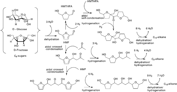 | ||
| Fig. 10 Routes for production of liquid alkanes through aqueous-phase processing of biomass feedstocks. Adapted from Huber et al., 2005.36 | ||
One of the challenges with aqueous-phase processing is that feedstocks need to be purified. Unlike gasification or selective thermal processing, which can be carried out with mixture of biomass-derived feedstocks, only pretreated reactants (e.g., sugars or polyols) can be effectively converted in liquid phase processing. Yet batch mode aqueous-phase reforming system has lately showed its capability in hydrogen production by converting real lignocellulosic biomass using Pt/Al2O3.59 Another issue is catalytic stability under liquid phase conditions. Traditional heterogeneous catalysts have been designed for high temperature gas phase reactions. Most of them are not stable in aqueous media, i.e., leaching is a common problem. Alternatively, the low temperature, liquid phase environment allow us to take advantage of chemical phenomena that are unique to the liquid phase. For example, ionic liquids can produce targeted compounds such as 5-hydroxymethylfurfural (HMF), a key intermediate to produce liquid alkanes, from sugars at this platform.60
3.4 Integration with the petrochemical refinery
The petroleum refinery can also be used to prepare biofuels. The advantage of this approach is that refineries are already built and this provides a low capital cost route to make biofuels. Several oil companies are evaluating this possibility. Universal Oil Corporation (UOP) has recently reported how biofuels can be prepared in a petroleum refinery.61 Its joint effort with ENSYN is trying to make hydrotreating of bio-oils to diesel and jet fuel in existing refineries a reality.62 Neste Oil has also adopted hydrotreating of the mix of vegetable oils and animal fats to synthesize diesel fuels.63 Total Oil in their “Biomass-to-Energy” roadmap is exploring integration of biomass gasification into a refinery.64 The infrastructure for blending biofuels as well as their testing and distribution is already in place at oil refineries.There are at least three options for using petroleum refineries to convert biomass into fuels and chemicals: (1) utilization of biomass-derived syngas or hydrogen, (2) fluid catalytic cracking (FCC), and (3) hydrotreating–hydrocracking.65 FCC is the most widely used process for conversion of heavy fraction of crude oils into gasoline or other hydrocarbons in oil refineries.17,66 Hydrotreating–hydrocracking is employed to remove sulfur (hydrodesulfurization, HDS), nitrogen (hydrodenitrogenation, HDN), metals (hydrodemetallization, HDM), and oxygen (hydrodeoxygenation) by hydrogenation of heavy petroleum feedstocks.10,65 Both of these approaches can remove oxygen from petroleum-derived resources. In this respect, they are also able to extract oxygen from biomass feedstocks – the major objective for biofuels preparation.65
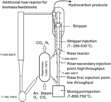
Fig. 11 depicts the design of a FCC reactor, which consists of multiple reactor units. In the riser reactor, the vaporized hydrocarbons reactants are mixed with the catalyst and a fluidizing gas which pushes both the catalyst and reactants up the riser reactor tube. The residence time of the catalyst in the riser reactor is less than 2 s.10 The products and catalysts are then separated in the separator. The spent catalysts, which contain carbon from the reactant, are then regenerated by addition of oxygen to the catalysts which burns the coke off. The regeneration step produces all of the necessary processing heat for the FCC process. Biomass can be injected into a number of different sections of the FCC reactor including mixing pot injector, various parts of the riser reactor, and the stripper.67 These zones have different reaction temperatures.
Commercial hydrotreating–hydrocracking reactors are mainly fixed beds of either down flow or radial flow designs.68 The reactions are carried out at 300–600 °C with H2 pressure of 35–170 atm by using sulfided Co/Mo/Al2O3 and Ni/Mo/Al2O3catalysts. Catalytic promoters, e.g., boron and phosphorus, are frequently added. Non-sulfided catalysts, including Pt/SiO2/Al2O3,69vanadium nitride,70 and Ru,71 have also been used for hydrodeoxygenation. A detailed review which focuses on the chemistry of catalytic hydrodeoxygenation has been published by Furimsky.72
Elliott and collaborators developed a two-step hydrotreating process for the upgrading of bio-oils using sulfided Co/Mo/Al2O3 and sulfided Ni/Mo/Al2O3catalysts.73 Keys in pretreatment of reactants, optimized reaction condition, and hydrogen consumption estimation were reported. Corma and coworkers prepared straight chain alkanes by hydrotreating of sunflower oils in heavy vacuum oil mixtures.74 Based on the results, they envisioned that such technique can be used on other vegetable oils.
4. Challenge and opportunity
Today there is a significant need to rapidly develop new technologies that will allow us to convert our biomass-derived resources into fuels and chemicals. In this respect, a large amount of applied research has been done focused primarily on empirical exploration. However, few studies have focused on the fundamentals of biomass refining. These essential studies are critical for advanced improvements in biofuels quality, process optimization, as well as integration with petrochemical infrastructures. Efficient catalysts that are selective, stable and active for conversion of biomass-derived feedstocks must be developed by combining fundamental with applied research.4.1 Chemistry of biomolecules
Understanding the bonding of atomic bonds in the biomolecules can explain their physical and chemical properties. Nevertheless, the number of biomolecules could be enormous in the biorefinery. For example, in the petrorefinery, the number of components involved exceeds 104 while the number of plausible reaction pathways can be an order of magnitude greater.75 Hence, it is impractical to catalogue each species individually. The development of the petroleum industry has provided the lessons to systematically manage a complex system by the so-called lumping analysis. The core of this approach is to partition all the species into several classes (e.g., paraffins, olefins, naphthenes, and aromatics, abbreviated as PONA), and simply treat each class as an unique entity.76 This can substantially minimize the complexity of mixture system and provide valuable information, such as prediction of gasoline yields. Decades later, this lumping analysis has been renewed as structure-oriented lumping (SOL),77 by which the structurally similar molecules are grouped according to mathematical formalism on the molecular level. Such methods have provided refiners with a valuable database which archives the properties of reactants, products, and mixtures of them, the optimal operating conditions, and the capability in predicting the refining outcomes. Indeed, to establish an efficient and economic biorefinery will require the development of such a database.Lignocellulosic biomass is mainly composed of three polymers: cellulose, hemicellulose, and lignin. Cellulose is the only crystalline material in biomass consisting of linear chains (1–4 in the β-configuration) of glucose units. Hemicellulose is a heterogeneous, branched sugar polymer. Its monomers contain almost entirely five-carbon (xylose and arabinose) and six-carbon sugars (galactose, glucose, and mannose). Lignin is a polyaromatic compound, with coumaryl, coniferyl, and sinapyl as the building blocks.1Hemicellulose and lignin are amorphous polymers. Synergistic efforts between SOL, novel analytical techniques, and long-term recording of environmental impacts may be the way to clarify the nature of biomass.
The research of biomass chemistry should be undertaken in parallel with thermodynamic studies. Thermodynamics allows engineers to evaluate the feasibility of new processes, reactor designs, and reaction pathways. For instance, the changes of standard Gibbs free energy have been applied to predict the performances of steam reforming of multiple oxygenated hydrocarbons.36 The knowledge of thermodynamics can investigate the interactions between reactants, products and intermediates with catalytic surface, as well as bi- or tri-phasic behaviors in the reactor. In this respect, thermodynamic analysis of the whole biorefinery system, whether the process is a chemical transformation or a separation step, should be carried out.7
4.2 Catalysis science and engineering
The evolution of heterogeneous catalysis in the 21st century must fulfil three characteristics conveyed throughout this review – activity, selectivity, and stability. The least understood is manipulation of selectivity.78 An ultimate goal for catalysis researchers is to achieve 100% selectivity of the desired product, namely, no unwanted by-product is generated.79 This not only spares the costs of feedstock and waste treatment, but also increases energy efficiency for manufacturing. To meet this thrust, the art of catalyst preparation must advance from catalyst discovery toward catalyst design.5,28 Catalysis science and engineering which allow molecular control over the size, location, structure of metallic nanoparticles and catalytic promoters must be developed.79 Such progress will facilitate the buildup of emerging biorefineries. For example, heterogeneous catalysts can selectively manipulate the breakage of C–C, C–O and C–H bonds for the purpose of oxygen removal from biomass-based feedstocks.Several groups are exploiting simple, rational methods to make metallic nanoparticles that are evenly distributed on metal oxide supports. Somorjai's group employed lithographic techniques to synthesize nanoparticle array and combined nanoparticle/mesoporous metal oxide for high surface area catalysts.79 Nearly uniform size and distribution of Pt nanoparticle array can be grown on SiO2 as 1-, 2-, or even 3-dimensional structures.79 Their recent effort on seedless polyol method can selectively synthesize single crystalline Rh nanocubes (enclosed by six {1 0 0} faces with size about 6.5 nm). The catalysts made from these nanocubes in hydrogenation of pyrrole showed 100% selectivity of butane and ammonia.80 Katz and coworkers applied outer-sphere control to design the active sites of heterogeneous catalysts. This can be accomplished by binding a chromophore that reports on the acidity and dielectric constant surrounding the active sites, and is demonstrated for primary amines anchored on silica.81 Regalbuto and his collaborators used strong electrostatic adsorption to yield also ultra-fine Pt particles on SiO2 with 100% dispersion.82 These works shed some light on how the future catalysts should be fabricated, particularly for those used in a complex system like a biorefinery.
The above-mentioned developments could not be fulfilled without an atomic-scale understanding of catalytic chemistry. Identification of the active catalytic sites needs to be done for rational catalyst design.83 Detailed characterization under ambient (ex situ) and under reaction conditions (in situ) allow us to qualitatively derive “structure–function” relationships. More comprehensive texts about characterization techniques for a host of catalytic materials and applications can be found elsewhere.84
With the improvement and development of characterization technology in the past decades, ex situ and in situ investigations of gas phase catalytic reactions can be easily conducted. Gas and liquid chromatographies (GC/LC) still serve as the vital tools in quantification today. Annexing mass spectrometry (MS) enables both chromatographies to qualitative analysis in real time. High resolution electron microscopies (HREM) are frequently employed in surveying the surface of catalysts. Electron microscopies can also be used for in situ characterization in which catalyst surface under reaction conditions can be observed. Infrared (IR), Raman, and ultraviolet visible (UV–vis) spectroscopies are typically used in operando observations of reactive intermediates as well as active sites.
Thus far, most of the surface analytical techniques require moisture removal prior to analysis. This limits the study of biomass conversion at the solid/liquid (heterogeneous catalysts/biomass solution) interface. It is well known that IR spectroscopy suffers from excessive absorption of IR radiation from water, while classical ultra-high vacuum (UHV) electronic spectroscopies can be dampened by adsorption and scattering of ejected electrons. Moreover, under in situ environments, water molecules may be split into H+ and OH−, which mediate undesired reaction pathways than those by active sites in reality. Apparently, developing surface-sensitive in situ spectroscopic instruments which are capable of surveying the solid/liquid interface is required. Techniques including surface enhanced Raman and attenuated total reflectance IR spectroscopies are currently used as the interfacial analysis tools.85 With advances in spectrometer speed and sensitivity, these tools may be widely used in this arena.
Another challenge is that the structure of solid catalysts can be influenced by solution pH, ionic strength, surfactants, temperature, etc. This results in segregation, disruption and migration of active sites, as well as dissolution of support, depending on the reaction environments.86 Moreover, trace impurities present in biomass feedstocks or formed by-products may selectively poison catalyst surfaces.87 For instance, trace amount (ca. 15 ppm) of sulfur in glucose solution can rapidly deactivate ruthenium catalyst in glucose hydrogenation.88In situ spectroscopic, scattering, and imaging tools that combined with real-time monitoring of the catalyst structure at the nanometer level is one option. High-energy X-ray methods are particularly suitable for investigating the structure of catalysts in water.89
4.3 Computational chemistry
Advances in computational powers have made it possible to study catalysts from a first principles approach. Multiple new approaches have been recently developed for computational study of catalysts, including modelling atomic-level structure in both bulk and surface phases, elucidating mechanisms of molecular adsorption and diffusion, and simulating reaction mechanisms of intermediates on active sites etc.90 One successful example is modelling of zeolite chemistry.91 In certain cases, theoretical techniques can predict hitherto undiscovered chemical phenomena. By complementing with experimental characterizations, an insight-view about biomass conversion on catalytic surface can be achieved.Current theoretical methods can be divided into two groups: classical molecular simulations and quantum mechanistic calculations. The former includes energy minimization (EM), Monte Carlo (MC), and molecular dynamics (MD); while the latter contains Hartree–Fock (HF) and density functional theory (DFT). In general, classical molecular simulations are applied to modelling structures, adsorption–desorption, and anchored intermediates on the premise of refined key configurations. Quantum mechanistic calculations are mainly used in simulation of reaction mechanisms.90 Several groups have embedded these two in identifying systems with high complexity, e.g., DFT calculation on reactive catalytic system combined with classical modelling of the solvents.92
Auerbach and coworkers employed DFT calculation on the design of zeolites used in biofuels manufacturing.93Fig. 12 depicts the mechanism of amine-functionalization of silicalite. It results in a shape-selective material with catalytically active base sites twice as strong as without such amine-functionalization. These materials show potential in steering reactions such as aldol condensation of biomass-derived oxygenates, which leads to increased molecule size from 5–6 carbons to 8–9 carbons. Neurock's group studied theoretical description of molecular and atomic interactions occurring at the interface between an aqueous solution and a metal surface. They discovered that the solution phase can actually stabilize charged transition states in some reactions and can even directly participate in the reaction.94
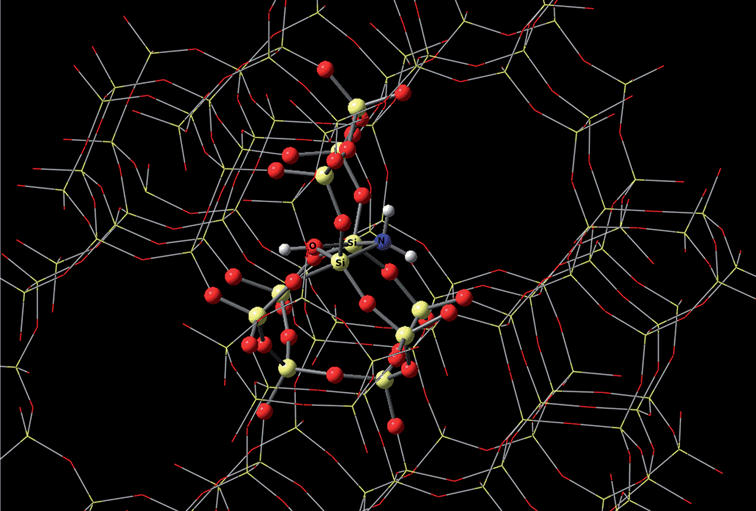 | ||
| Fig. 12 The mechanism of amine-functionalization of silicalite based on DFT calculation. Photo courtesy of Scott M. Auerbach. | ||
Nevertheless, theoretically modelling a biorefinery is a daunting task for most theorists. The biomolecules are large and contain many flexible bonds, leading to a huge number of low energy structures and frequent anharmonic motions. Furthermore, solid phase biomass substrates (such as fragments of cellulose, hemicellulose, and lignin) may be encompassed inside the system. Most of the reactions of biomass occur in solution or at interfaces, thereby the reaction environment is critical in the modelling.7
5. Conclusion
The field of heterogeneous catalysis has immense potential to help convert renewable feedstocks into fuels and chemicals. Lignocellulosic biomass is the most abundant and fastest growing organic carbon source, which provides opportunities for producing a significant amount of biomass-derived fuels and chemicals. It is likely that just as heterogeneous catalysis has made it possible to efficiently convert our petroleum-derived resources to fuels and chemicals; it will also allow us to convert our renewable resources to fuels and chemicals. There are currently multiple catalytic processes for production of lignocellulosic biofuels. However, most of these approaches have been primarily empirical, focusing on the quick development of a commercial process. There is a great need to have fundamental studies for biomass conversion. Advances in chemistry, nanotechnology and spectroscopy over the last several decades have given us an unprecedented ability to understand and control chemistry at the molecular scale, which promises to accelerate the development of biomass-to-fuels production technologies. As the tremendous expertise of the catalysis field focuses on biomass conversion, it is highly likely that we will rapidly develop cost-effective approaches to the conversion of biomass to biofuels.Acknowledgements
The authors appreciate the financial support from National Science Council (Taiwan) under Project No. NSC-096-2917-I-564-114.References
- G. W. Huber, S. Iborra and A. Corma, Chem. Rev., 2006, 106, 4044–4098 CrossRef CAS.
- J. N. Chheda, G. W. Huber and J. A. Dumesic, Angew. Chem., Int. Ed., 2007, 46, 7164–7183 CrossRef CAS.
- L. D. Schmidt and P. J. Dauenhauer, Nature, 2007, 447, 914–915 CrossRef CAS.
- L. R. Lynd, C. E. Wyman and T. U. Gerngross, Biotechnol. Prog., 1999, 15, 777–793 CrossRef CAS.
- A. T. Bell, B. C. Gates, D. Ray and M. R. Thompson, Basic Research Needs: Catalysis for Energy, Technical Report, U.S. Department of Energy, PNNL-17214, 2008 Search PubMed.
- T. P. Vispute and G. W. Huber, Int. Sugar J., 2008, 110, 138–149 Search PubMed.
- National Science Foundation, Breaking the Chemical and Engineering Barriers to Lignocellulosic Biofuels: Next Generation Hydrocarbon Biorefineries, ed. G. W. Huber, National Science Foundation - Division of Chemical, Bioengineering, Environmental, and Transport Systems, Washington, DC, 2008 Search PubMed.
- B. C. Gates, G. W. Huber, C. L. Marshall, P. N. Ross, J. Siirola and Y. Wang, MRS Bull., 2008, 33, 429–435 CAS.
- Catalysis Looks to the Future. Panel on New Directions in Catalytic Science and Technology, Technical Report, National Academy of Sciences - National Research Council, DOE/ER/14103-T1, Washington, DC, 1992 Search PubMed.
- C. H. Bartholomew and R. J. Farrauto, in Fundamentals of Industrial Catalytic Processes, Wiley Interscience, Hoboken, NJ, 2nd edn, 2006 Search PubMed.
- D. L. Klass, in Encyclopedia of Energy, ed. C. J. Cleveland, Elsevier, London, 2004, pp. 193–212 Search PubMed.
- W. Z. Ostwald, Physik. Chem., 1894, 15, 705–706 Search PubMed.
- S. T. Oyama and G. A. Somorjai, J. Chem. Educ., 1988, 65, 765–769 CrossRef CAS.
- M. Boudart, in Perspective in Catalysis, ed. J. M. Thomas and K. I. Zamaraev, Blackwell, Oxford, 1992, pp. 183 Search PubMed.
- J. A. Dumesic, G. W. Huber and M. Boudart, in Introduction: Principles of Heterogeneous Catalysis, ed. G. Ertl, Wiley-VCH, Weinheim, Germany, 2nd edn, 2008, vol. 1, pp. 1–15 Search PubMed.
- G. C. Bond, in Heterogeneous Catalysis: Principles and Applications, Clarendon Press, Oxford, 2nd edn, 1987 Search PubMed.
- C. N. Satterfield, in Heterogeneous Catalysis in Industrial Practice, McGraw-Hill, New York, 2nd edn, 1991 Search PubMed.
- J. M. Thomas and W. J. Thomas, in Principles and Practice of Heterogeneous Catalysis, VCH, Weinheim, 1997 Search PubMed.
- T. A. Garibyan and L. Y. Margolis, Catal. Rev. Sci. Eng., 1989, 31, 355–384 CrossRef CAS; T. A. Garibyan, R. R. Grigoryan, L. A. Zeile, L. N. Kurina and O. D. Filicheva, Kinet. Catal., 1990, 31, 322–326; J. M. Thomas and J. P. Williams, Philos. Trans. R. Soc. London, Ser. A, 2005, 363, 765–791 CrossRef CAS; A. Corma and H. Garcia, Top. Catal., 2008, 48, 8–31 CrossRef CAS.
- H. S. Taylor, Proc. R. Soc. London, Ser. A, 1925, A108, 105–111.
- M. Boudart, Chem. Rev., 1995, 95, 661–666 CrossRef CAS.
- M. Boudart, Adv. Catal., 1969, 20, 153–166 CAS.
- S. H. Fogler, in Elements of Chemical Reaction Engineering, Prentice Hall, Upper Saddle River, NJ, 3rd edn, 1999 Search PubMed.
- D. R. Rolison, Science, 2003, 299, 1698–1701 CrossRef CAS.
- A. Wheeler, Adv. Catal., 1951, 3, 249–327.
- N. Y. Chen, W. E. Garwood and F. G. Dwyer, in Shape Selective Catalysis in Industrial Applications, Marcel Dekker, New York, 2nd edn, 1996, vol. 65, (ch. 2), pp. 6–36 Search PubMed.
- C. Baerlocher, W. M. Meier and D. H. Olson, in Atlas of Zeolite Structure Types, Elsevier, London, 5th edn, 2001 (updates on http://www.iza-structure.org/) Search PubMed.
- J. M. Thomas and J. Klinowski, Angew. Chem., Int. Ed., 2007, 46, 7160–7163 CrossRef CAS.
- N. Y. Chen, T. F. Degnan and L. R. Koenig, Chemtech, 1986, 16, 506–511 CAS; R. W. Thring, S. P. R. Katikaneni and N. N. Bakhshi, Fuel Process. Technol., 2000, 62, 17–30 CrossRef CAS.
- A. Corma, G. W. Huber, L. Sauvanaud and P. O'Connor, J. Catal., 2007, 247, 307–327 CrossRef CAS.
- T. R. Carlson, T. P. Vispute and G. W. Huber, ChemSusChem, 2008, 1, 397–400 CrossRef CAS.
- R. Hughes, in Deactivation of Catalysts, Academic Press, London, 1984 Search PubMed.
- D. L. Trimm, Appl. Catal., A, 2001, 212, 153–160 CrossRef CAS.
- G. W. Huber, International Assessment of Catalysis Research, World Technology Evaluation Center, in press Search PubMed.
- B. G. Hermann and M. Patel, Appl. Biochem. Biotechnol., 2007, 136, 361–388 CrossRef CAS.
- G. W. Huber, J. W. Shabaker and J. A. Dumesic, Science, 2003, 300, 2075–2077 CrossRef CAS; G. W. Huber, R. D. Cortright and J. A. Dumesic, Angew. Chem., Int. Ed., 2004, 43, 1549–1551 CrossRef CAS; G. W. Huber, J. N. Chheda, C. J. Barrett and J. A. Dumesic, Science, 2005, 308, 1446–1450 CrossRef CAS; R. R. Davda, J. W. Shabaker, G. W. Huber, R. D. Cortright and J. A. Dumesic, Appl. Catal., B, 2005, 56, 171–186 CrossRef CAS; G. W. Huber and J. A. Dumesic, Catal. Today, 2006, 111, 119–132 CrossRef CAS.
- Choren, http://www.choren.com/en/biomass_to_energy/carbo-v_technology/ (accessed September, 2008).
- Coskata, http://www.coskata.com/ProcessGasification.asp (accessed September, 2008).
- Range Fuels, http://www.rangefuels.com/conversion_process (accessed September, 2008).
- O. Levenspiel, Ind. Eng. Chem. Res., 2005, 44, 5073–5078 CrossRef CAS.
- M. Marchionna, M. Di Girolamo, L. Tagliabue, M. J. Spangler and T. H. Fleisch, Stud. Surf. Sci. Catal., 1998, 119, 539–544 CAS; A. Y. Rozovskii and G. I. Lin, Kinet. Catal., 1999, 40, 773–794 CAS; P. J. A. Tijm, F. J. Waller and D. M. Brown, Appl. Catal., A, 2001, 221, 275–282 CrossRef CAS.
- H. H. Storch, N. Golumbic and R. B. Anderson, in The Fischer-Tropsch and Related Syntheses, Wiley, New York, 1951 Search PubMed; M. E. Dry, in Catalysis Science and Technology, ed. J. R. Anderson and M. Boudart, Springer-Verlag, New York, 1981 Search PubMed; R. B. Anderson, in The Fischer-Tropsch Synthesis, Academic Press, Orlando, FL, 1984 Search PubMed; G. P. Van der Laan and A. Beenackers, Catal. Rev. Sci. Eng., 1999, 41, 255–318 Search PubMed.
- W. Torres, S. S. Pansare and J. G. Goodwin, Catal. Rev. Sci. Eng., 2007, 49, 407–456 CAS.
- S. Rapagná, H. Provendier, C. Petit, A. Kiennemann and P. U. Foscolo, Biomass Bioenergy, 2002, 22, 377–388 CrossRef CAS.
- D. S. Newsome, Catal. Rev. Sci. Eng., 1980, 21, 275–318 CrossRef.
- J. R. Salge, B. J. Dreyer, P. J. Dauenhauer and L. D. Schmidt, Science, 2006, 314, 801–804 CrossRef CAS; P. J. Dauenhauer, B. J. Dreyer, N. J. Degenstein and L. D. Schmidt, Angew. Chem., Int. Ed., 2007, 46, 5864–5867 CrossRef CAS.
- D. J. Stevens, Review and Analysis of the 1980–1989 Biomass Thermochemical Conversion Program, Technical report, US Department of Energy, NREL/TP-421-7501, 1994 Search PubMed.
- A. V. Bridgwater, Catal. Today, 1996, 29, 285–295 CrossRef CAS; A. V. Bridgwater, J. Anal. Appl. Pyrolysis, 1999, 51, 3–22 CrossRef CAS; A. V. Bridgwater, D. Meier and D. Radlein, Org. Geochem., 1999, 30, 1479–1493 CrossRef; S. Czernik and A. V. Bridgwater, Energy Fuels, 2004, 18, 590–598 CrossRef.
- A. V. Bridgwater and S. A. Bridge, in Biomass Pyrolysis Liquids Upgrading and Utilisation, ed. A. V. Bridgwater and G. Grassi, Elsevier, Amsterdam, 1991, pp. 11–92 Search PubMed; A. V. Bridgwater, Appl. Catal., A, 1994, 116, 5–47 Search PubMed; D. Wang, S. Czernik, D. Montane, M. Mann and E. Chornet, Ind. Eng. Chem. Res., 1997, 36, 1507–1518 CrossRef CAS; J. P. Diebold, in A Review of the Chemical and Physical Mechanisms of the Storage Stability of Fast Pyrolysis Bio-oils, ed. A. V. Bridgwater, CPL Press, Newbury, UK, 2002, vol. 2, pp. 243–292 CrossRef CAS; D. C. Elliott, Energy Fuels, 2007, 21, 1792–1815 CrossRef CAS.
- L. Garcia, R. French, S. Czernik and E. Chornet, Appl. Catal., A, 2000, 201, 225–239 CrossRef CAS; C. Rioche, S. Kulkarni, F. C. Meunier, J. P. Breen and R. Burch, Appl. Catal., B, 2005, 61, 130–139 CrossRef CAS.
- D. C. Elliott, J. Hu, T. R. Hart and G. G. Neuenschwander, Palladium Catalyzed Hydrogenation of Bio-oils and Organic Compounds, US Pat., 7 425 657, 2008 Search PubMed.
- P. C. Badger and P. Fransham, Biomass Bioenergy, 2006, 30, 321–325 CrossRef CAS.
- J. M. Moffat and R. P. Overend, Biomass, 1985, 7, 99–123 CrossRef; F. Goudriaan and D. G. R. Peferoen, Chem. Eng. Sci., 1990, 45, 2729–2734 CrossRef CAS.
- A. Demirbas, Energy Convers. Manage., 2001, 42, 1357–1378 CrossRef CAS.
- D. C. Elliott, D. Beckman, A. V. Bridgwater, J. P. Diebold, S. B. Gevert and Y. Solantausta, Energy Fuels, 1991, 5, 399–410 CrossRef CAS.
- A. A. Peterson, F. Vogel, R. P. Lachance, M. Fröling, M. J. Antal and J. W. Tester, Energy Environ. Sci., 2008, 1, 32–65 RSC.
- E. H. Salter, N. M. Robinson, G. V. C. Peacocke, H. Sheena and A. V. Bridgwater, Catalysis Fast Pyrolysis of Biomass, in IChemE Research Event, A Two-Day Symposium, Newcastle upon Tyne, 1998, p. 89–96 Search PubMed; S. Ritter, Chem. Eng. News, 2008, 86, 10 Search PubMed.
- KiOR, http://www.kior.com/(accessed August, 2008).
- M. B. Valenzuela, C. W. Jones and P. K. Agrawal, Energy Fuels, 2006, 20, 1744–1752 CrossRef CAS.
- H. Zhao, J. E. Holladay, H. Brown and Z. C. Zhang, Science, 2007, 316, 1597–1600 CrossRef CAS.
- T. L. Marker, J. Petri, T. Kalnes, M. McCall, D. Mackowiak, B. Jerosky, B. Reagan, L. Nemeth, M. Krawczyk, S. Czernik, D. Elliott and D. Shonnard, Opportunities for Biorenewables in Oil Refineries, Technical Report, US Department of Energy - Office of Energy Efficiency and Renewable Energy, DOEGO15085, 2005 Search PubMed.
- UOP, http://www.uop.com/renewables/presentations/world%20biofuels%20congress08%20-%20bioaviation%20fuel.pdf (accessed September, 2008).
- Neste Oil, http://www.nesteoil.com/default.asp?path = 1,41, 539, 7516, 7522 (accessed September, 2008).
- Total Oil, http://www.total.com/static/en/medias/topic1612/Total_2007_biomass_to_energy.pdf (accessed August, 2008).
- G. W. Huber and A. Corma, Angew. Chem., Int. Ed., 2007, 46, 7184–7201 CrossRef CAS.
- A. Corma and B. W. Wojciechowski, Catal. Rev. Sci. Eng., 1985, 27, 29–150 CrossRef CAS.
- A. Corma, G. W. Huber, L. Sauvanaud and P. O'Connor, J. Catal., 2008, 257, 163–171 CrossRef CAS.
- D. C. McCulloch, in Catalytic Hydrotreating in Petroleum Refining, Academic Press, New York, 1983 Search PubMed.
- Y.-H. E. Sheu, R. G. Anthony and E. J. Soltes, Fuel Process. Technol., 1988, 19, 31–50 CrossRef CAS.
- S. Ramanathan and S. T. Oyama, J. Phys. Chem., 1995, 99, 16365–16372 CrossRef CAS.
- A. Centeno, R. Maggi and B. Delmon, Stud. Surf. Sci. Catal., 1999, 127, 77–84 CAS.
- E. Furimsky, Appl. Catal., A, 2000, 199, 147–190 CrossRef CAS.
- D. C. Elliott, E. G. Baker, J. Piskorz, D. S. Scott and Y. Solantausta, Energy Fuels, 1988, 2, 234–235 CrossRef CAS; D. C. Elliott and A. Oasmaa, Energy Fuels, 1991, 5, 102–109 CrossRef CAS.
- G. W. Huber, P. O'Connor and A. Corma, Appl. Catal., A, 2007, 329, 120–129 CrossRef CAS.
- R. J. Quann, Environ. Health Perspect., 1998, 106, 1441–1448 CAS.
- J. Wei and J. C. W. Kuo, Ind. Eng. Chem. Fundam., 1969, 8, 114–123 CrossRef CAS; S. M. Jacob, B. Gross, S. E. Voltz and V. W. Weekman, AIChE J., 1976, 22, 701–713 CrossRef CAS.
- R. J. Quann and S. B. Jaffe, Ind. Eng. Chem. Res., 1992, 31, 2483–2497 CrossRef CAS; S. B. Jaffe, H. Freund and W. N. Olmstead, Ind. Eng. Chem. Res., 2005, 44, 9840–9852 CrossRef CAS.
- F. Zaera, J. Phys. Chem. B, 2002, 106, 4043–4052 CrossRef CAS.
- J. Grunes, J. Zhu and G. A. Somorjai, Chem. Commun., 2003, 2257–2260 RSC; G. A. Somorjai and M. C. Yang, Top. Catal., 2003, 24, 61–72 CrossRef CAS; G. A. Somorjai and R. M. Rioux, Catal. Today, 2005, 100, 201–215 CrossRef CAS.
- Y. W. Zhang, M. E. Grass, J. N. Kuhn, F. Tao, S. E. Habas, W. Y. Huang, P. D. Yang and G. A. Somorjai, J. Am. Chem. Soc., 2008, 130, 5868–5869 CrossRef CAS.
- J. D. Bass, S. L. Anderson and A. Katz, Angew. Chem., Int. Ed., 2003, 42, 5219–5222 CrossRef CAS; J. D. Bass, A. Solovyov, A. J. Pascall and A. Katz, J. Am. Chem. Soc., 2006, 128, 3737–3747 CrossRef CAS.
- M. Schreier and J. R. Regalbuto, J. Catal., 2004, 225, 190–202 CrossRef CAS; J. T. Miller, M. Schreier, A. J. Kropf and J. R. Regalbuto, J. Catal., 2004, 225, 203–212 CrossRef CAS.
- C. H. Christensen and J. K. Nøskov, J. Chem. Phys., 2008, 128, 182503–182508 CrossRef.
- C. R. Brundle, C. A. J. Evans and S. Wilson, in Encyclopedia of Materials Characterization: Surfaces, Interfaces, Thin Films, Butterworth-Heinemann, Boston, 1992 Search PubMed; I. E. Wachs, in Characterization of Catalytic Materials, Butterworth-Heinemann, Boston, 1992 Search PubMed; J. W. Niemantsverdriet, in Spectroscopy in Catalysis: An Introduction, Weinheim, New York, 1993 Search PubMed.
- D. Ferri, T. Burgi and A. Baiker, J. Phys. Chem. B, 2001, 105, 3187–3195 CrossRef CAS; A. R. Hind, S. K. Bhargava and A. McKinnon, Adv. Colloid Interface Sci., 2001, 93, 91–114 CrossRef CAS; A. J. McQuillan, Adv. Mater., 2001, 13, 1034–1038 CrossRef; D. Ferri, T. Burgi and A. Baiker, Phys. Chem. Chem. Phys., 2002, 4, 2667–2672 RSC; I. Ortiz-Hernandez and C. T. Williams, Langmuir, 2003, 19, 2956–2962 CrossRef CAS.
- D. C. Elliott, Use of Heterogeneous Catalysts in Aqueous Phase Processing of Biomass and Waste, in ACS National Meeting, 223rd, American Chemical Society, Orlando, FL, 2002 Search PubMed; F. A. Marchesini, S. Irusta, C. Querini and E. Mir, Catal. Commun., 2008, 9, 1021–1026 Search PubMed.
- M. Besson and P. Gallezot, Catal. Today, 2003, 81, 547–559 CrossRef CAS.
- B. J. Arena, Appl. Catal., A, 1992, 87, 219–229 CrossRef CAS.
- E. P. Maris, W. C. Ketchie, V. Oleshko and R. J. Davis, J. Phys. Chem. B, 2006, 110, 7869–7876 CrossRef CAS; W. C. Ketchie, E. P. Maris and R. J. Davis, Chem. Mater., 2007, 19, 3406–3411 CrossRef CAS; W. C. Ketchie, M. Murayama and R. J. Davis, J. Catal., 2007, 250, 264–273 CrossRef CAS; E. P. Maris, W. C. Ketchie, M. Murayama and R. J. Davis, J. Catal., 2007, 251, 281–294 CrossRef CAS.
- C. R. A. Catlow, L. Ackermann, R. G. Bell, D. H. Gay, S. Holt, D. W. Lewis, N. A. Nygren, G. Sastre, D. C. Sayle and P. E. Sinclair, in A Molecular View of Heterogeneous Catalysis, ed. E. G. Derouane, De Boeck & Larcier, Paris, 1998, vol. 1, (ch. 7), pp. 107–131 Search PubMed.
- C. R. A. Catlow, in Modelling of Structure and Reactivity in Zeolites, ed. C. R. A. Catlow, Academic Press, London, 1992 Search PubMed; J. M. Newsam and Y. S. Li, Catal. Today, 1995, 23, 325–332 Search PubMed; J. M. Newsam, Stud. Surf. Sci. Catal., 1996, 102, 231–265 CrossRef CAS.
- K. Sillar and P. Purk, J. Mol. Struct. Theochem., 2002, 589, 281–290 CrossRef; J. T. Fermann, T. Moniz, O. Kiowski, T. J. Mclntire, S. M. Auerbach, T. Vreven and M. J. Frisch, J. Chem. Theory Comput., 2005, 1, 1232–1239 CrossRef CAS.
- R. Astala, S. M. Auerbach and P. A. Monson, J. Phys. Chem. B, 2004, 108, 9208–9215 CrossRef CAS; R. Astala and S. M. Auerbach, J. Am. Chem. Soc., 2004, 126, 1843–1848 CrossRef CAS.
- S. Desai and M. Neurock, Electrochim. Acta, 2003, 48, 3759–3773 CrossRef CAS; C. D. Taylor and M. Neurock, Curr. Opin. Solid State Mater. Sci., 2005, 9, 49–65 CrossRef CAS.
| This journal is © The Royal Society of Chemistry 2009 |

