Facile scalable synthesis of magnetite nanocrystals embedded in carbon matrix as superior anode materials for lithium-ion batteries†
Yuanzhe
Piao‡
*ab,
Hyun Sik
Kim‡
c,
Yung-Eun
Sung
*c and
Taeghwan
Hyeon
*a
aNational Creative Research Initiative Center for Oxide Nanocrystalline Materials and School of Chemical and Biological Engineering, Seoul National University, Seoul, 151-744, Korea. E-mail: thyeon@snu.ac.kr; Fax: +82-2-886-8457; Tel: +82-2-880-7150
bDepartment of Nano Science and Technology, Graduate School of Convergence Science and Technology, Seoul National University, Suwon, 443-270, Korea. E-mail: parkat9@snu.ac.kr; Tel: +82-31-888-9141
cSchool of Chemical and Biological Engineering and Research Center for Energy Conversion & Storage, Seoul National University, Seoul, 151-742, Korea. E-mail: eysung@snu.ac.kr; Tel: +82-2-880-1889
First published on 16th November 2009
Abstract
A simple and scalable process was developed for the synthesis of highly crystalline magnetite nanocrystals embedded in a carbon matrix using low cost starting materials; the resulting nanocomposite showed a very high specific capacity of 863 mA hg−1 in the initial cycle and high capacity retention of 90% after 30 cycles.
For the last two decades, rechargeable lithium-ion batteries have been widely used as power sources for various portable electronic devices such as laptop computers, digital cameras, and cellular phones.1 More recently, they have attracted growing attention as power supplies for electric vehicles and hybrid electric vehicles. The market demand for reduced cost, a high specific energy density and good cycling performance is ever increasing. Consequently, intensive research has been performed to develop new electrode materials with improved electrochemical performance for lithium-ion batteries. Recently, various oxide nanostructured materials have been investigated as potential anodes with a high energy density and long cycle performance.2 Among them, iron oxide nanocrystals, which have been extensively used as MRI contrast agents,3 are being studied as lithium battery anodes, because of their low cost and environmental benignity.4 However, most iron oxide nanomaterials show rapid capacity fading during cycling due to their intrinsically low electronic conductivity and aggregation during the cycling process. One of the most promising ways to improve their cyclability is to coat the nanomaterials with carbon,5 and there have been a few reports on the fabrication of carbon coated iron oxide nanomaterials for lithium battery anode applications.6 However, these methods include several time-consuming steps and a hydrothermal reaction in an autoclave, which hamper scalable synthesis.
Recently, we developed a so-called “wrap–bake–peel” process, which involves silica coating, heat treatment, and finally the removal of the silica layer, to transform the phases and structures of nanocrystals while preserving their nanostructural characteristics.7 Herein, we report the facile scalable synthesis of magnetite nanocrystals embedded in a carbon matrix (magnetite-C nanocomposite) by the simple heating of polyfurfuryl alcohol impregnated β-FeOOH nanorods. The magnetite-C nanocomposite shows a very high specific capacity of 863 mA hg−1 in the initial cycle and a high capacity retention of 90% after 30 cycles.
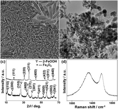
The synthetic process is represented in Fig. 1. Uniform spindle-shaped β-FeOOH nanoparticles were first prepared by the hydrolysis of aqueous iron chloride solution.8 Transmission electron microscopy (TEM) and scanning electron microscopy (SEM) images (Fig. 2a and Fig. S1a in Supporting Information†) showed that the β-FeOOH nanoparticles consisted of uniform spindle-shaped particles with a center diameter of 14 nm and length of 70 nm. The X-ray diffraction (XRD) pattern (Fig. 2c, bottom) matches very well with the β-FeOOH structure (JCPDS Card No. 75-1594). Furfuryl alcohol was impregnated in the β-FeOOH nanoparticles, followed by heating at 85 °C for 12 h under a static vacuum, forming polyfurfuryl alcohol-coated β-FeOOH nanoparticles.9 Finally, thermal treatment was performed at 600 °C for 5 h under a nitrogen atmosphere to obtain the magnetite-C nanocomposite. TEM and SEM images (Fig. 2b and Fig. S1b†) revealed that the nanoparticles had shrunk slightly, but were well-dispersed in the carbon matrix, demonstrating that their carbon shells effectively prevent their aggregation. The XRD pattern (Fig. 2c, top) showed that the core nanocrystals were highly crystalline with a magnetite structure (JCPDS Card No. 19-0629). No diffraction peak corresponding to graphitic carbon was observed in the XRD pattern, showing that the carbon coating is amorphous. The Raman spectrum (Fig. 2d) shows a D-band at 1340 cm−1 and a G-band at 1580 cm−1 with similar-intensities, which confirmed their amorphous carbon structure.10 When the bare β-FeOOH nanoparticles were heated, large micrometre-sized particles were generated (see Supporting Information Fig. S2†). Consequently, the in situ generated carbon coating serves not only as a physical barrier to prevent the aggregation of the nanocrystals, but also as a reducing agent to form a highly crystalline magnetite phase. The homogeneous mixing of the powdery nanoparticles in furfuryl alcohol and their subsequent polymerization by heating under a static vacuum turned out to be critical for the formation of the well-dispersed nanocomposite.11 When the mixture of furfuryl alcohol and the nanoparticles was heated without pre-heat treatment, a severely agglomerated powder was produced (see Supporting Information Fig. S3†).
 | ||
| Fig. 1 Synthetic scheme of the magnetite-C nanocomposites. | ||
 | ||
| Fig. 2 TEM images of (a) spindle-shaped β-FeOOH nanoparticles and (b) the magnetite-C nanocomposites. The insets in (a) and (b) panels show high-magnification TEM images. (c) XRD patterns of spindle-shaped β-FeOOH nanoparticles (bottom) and the magnetite-C nanocomposites (top). (d) Typical Raman spectrum of the magnetite-C nanocomposites. | ||
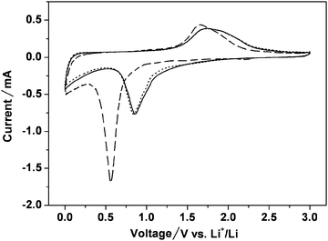
We studied the potential use of the as-prepared magnetite-C nanocomposite as an anode material for lithium-ion batteries. Fig. 3 shows the cyclic voltammetry (CV) curves of the magnetite-C nanocomposite for the first three cycles in the voltage range between 3.0 and 0.0 V at a scan rate of 0.1 mV s−1. In the first cycle, there is a broad peak at 0.57 V in the cathodic process, which could be associated with the reduction of Fe3+ and Fe2+ to Fe0 and the irreversible reaction related to the decomposition of the electrolyte. An anodic peak is present at 1.66 V, corresponding to the reversible oxidation of Fe0 to Fe3+. During the anodic process, both the peak current and the integrated area of the anodic peak are decreased, indicating capacity loss during the charging process. In the subsequent cycles, the cathodic and anodic peak potentials shift to 0.87 and 1.77 V, respectively. The CV curves of the magnetite-C nanocomposite electrode are stable and show good reversibility after the second cycle.
 | ||
| Fig. 3 Cyclic voltammograms of the magnetite-C nanocomposites. Voltage range of 0.0–3.0 V and scan rate of 0.1 mV s−1. Li metal was used for both the reference and counter electrodes. First cycle: – – –, second cycle: —, and third cycle: ……. | ||
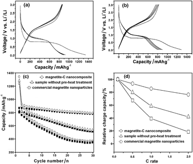
Fig. 4a shows the discharge/charge profiles of the magnetite-C nanocomposite. The as-prepared magnetite-C nanocomposite shows a very high capacity of 863 mA hg−1 in the initial cycle and excellent capacity retention of 90% of the initial capacity after 30 cycles at a constant current density of 100 mA g−1. Inductively coupled plasma atomic emission spectroscopic (ICP-AES) results showed that the magnetite-C nanocomposite has a chemical composition of 90.1 wt% Fe3O4 and 9.9 wt% carbon. The theoretical specific capacity based on the ICP-AES results was calculated to be 873 mA hg−1, demonstrating that the experimental capacity of 863 mA hg−1 approaches the maximum available value. The electrochemical properties of the sample prepared without pre-heat treatment under a vacuum (chemical composition of 91.2 wt% Fe3O4 and 8.8 wt% carbon, TEM and XRD data are shown in Fig. S3 in Supporting Information†) and the commercial magnetite nanoparticles (Aldrich, 20–30 nm in diameter, see Supporting Information Fig. S4†) were also investigated for the sake of comparison. The experimental results show that the specific charge capacity of both samples fades quickly (Fig. 4b and Fig. S5†), while the magnetite-C nanocomposite shows much better cycling performance (Fig. 4c). The TEM image of the magnetite-C nanocomposite in the fully de-lithiated state after 30 discharge/charge cycles clearly shows that the carbon matrix suppressed the aggregation of the iron oxide nanocrystals during cycling (see Supporting Information Fig. S6†). To evaluate the rate capability of the materials, the specific discharge–charge capacities at higher current rates were also measured. Fig. 4d plots the relative discharge capacities of three samples as a function of the discharge–charge C rate. Clearly, the rate performance of the magnetite-C nanocomposite was much better than that of commercial magnetite nanoparticles and the sample prepared without pre-heat treatment.
 | ||
| Fig. 4 The discharge/charge profiles of (a) the as-prepared magnetite-C nanocomposites, and (b) the sample prepared without pre-heat treatment under vacuum. (c) Cycle performance of each sample. Open symbols: discharge, closed symbols: charge. (d) Effect of current rate on the relative discharge capacities (the data were obtained by normalizing the third discharge capacities at various C rates to that at 0.1 C). | ||
The electrochemical performance of the magnetite-C nanocomposite is superior to that of similar, previously reported materials, and the magnetite-C nanocomposite has several advantages. Firstly, the conductive carbon shell enveloped the iron oxide nanocrystals and suppressed the aggregation of the core nanocrystals during cycling. Secondly, due to the nanometre particle size and high surface area, the kinetics of lithium intercalation and de-intercalation, the apparent diffusion coefficient of lithium ions, and the consequent cycling behavior are significantly enhanced.12 Thirdly, the intimate interaction of the conductive carbon shell with the core magnetite nanocrystals led to improved conductivity, which further improved the cycling performance. The current synthetic method is readily applicable for the scalable synthesis of the magnetite-C nanocomposite. For example, when 20 g of FeCl3·6H2O were reacted in 1 L of deionized water, 4.72 g of β-FeOOH nanoparticles were obtained, and 4.50 g of the final magnetite-C nanocomposite were produced (see Supporting Information Fig. S8†).
In summary, a simple and scalable process was developed for the synthesis of magnetite nanocrystals embedded in a carbon matrix using inexpensive starting materials such as iron chloride and furfuryl alcohol. The magnetite-C nanocomposite showed a very high capacity of 863 mA hg−1 in the initial cycle and excellent capacity retention of 90% of the initial capacity after 30 cycles. The current process is highly reproducible and expected to be extendable to the preparation of other carbon–metal oxide nanostructured materials.
We thank the Korean Ministry of Education, Science and Technology for financial support through the National Creative Research Initiative (T.H., R16-2002-003-01001-0) and the World Class University (T.H. and Y.-E.S. 400-2008-0230) Programs of the National Research Foundation of Korea (NRF). Y.P. is grateful for financial support from the Brain Korea (BK-21) program.
Notes and references
- (a) J.-M. Tarascon and M. Armand, Nature, 2001, 414, 359 CrossRef CAS; (b) M. S. Whittingham, Chem. Rev., 2004, 104, 4271 CrossRef CAS; (c) K. Xu, Chem. Rev., 2004, 104, 4303 CrossRef CAS; (d) K. Kang, Y. S. Meng, J. Bréger, C. P. Grey and G. Ceder, Science, 2006, 311, 977 CrossRef CAS; (e) M. Armand and J.-M. Tarascon, Nature, 2008, 451, 652 CrossRef CAS; (f) T. Ohzuku and R. J. Brodd, J. Power Sources, 2007, 174, 449 CrossRef CAS; (g) S. K. Martha, E. Markevich, V. Burgel, G. Salitra, E. Zinigrad, B. Markovsky, H. Sclar, Z. Pramovich, O. Heik, D. Aurbach, I. Exnar, H. Buqa, T. Drezen, G. Semrau, M. Schmidt, D. Kovacheva and N. Saliyski, J. Power Sources, 2009, 189, 288 CrossRef CAS.
- (a) P. Poizot, S. Laruelle, S. Grugeon, L. Dupont and J.-M. Tarascon, Nature, 2000, 407, 496 CrossRef CAS; (b) H.-J. Ahn, H.-C. Choi, K.-W. Park, S.-B. Kim and Y.-E. Sung, J. Phys. Chem. B, 2004, 108, 9815 CrossRef CAS; (c) H.-J. Ahn, K.-W. Park and Y.-E. Sung, Chem. Mater., 2004, 16, 1991 CrossRef CAS; (d) A. S. Arico, P. Bruce, B. Scrosati, J.-M. Tarascon and W. Van Schalkwijk, Nat. Mater., 2005, 4, 366 CrossRef CAS; (e) Y. Yu, C.-H. Chen, J.-L. Shui and S. Xie, Angew. Chem., Int. Ed., 2005, 44, 7085 CrossRef CAS; (f) S. Han, B. Jang, T. Kim, S. M. Oh and T. Hyeon, Adv. Funct. Mater., 2005, 15, 1845 CrossRef CAS; (g) Y. Yu, C.-H. Chen and Y. Shi, Adv. Mater., 2007, 19, 993 CrossRef CAS; (h) J. Hassoun, S. Panero, P. Simon, P. L. Taberna and B. Scrosati, Adv. Mater., 2007, 19, 1632 CrossRef CAS; (i) P. G. Bruce, B. Scrosati and J.-M. Tarascon, Angew. Chem., Int. Ed., 2008, 47, 2930 CrossRef CAS; (j) Y. Wang and G. Cao, Adv. Mater., 2008, 20, 2251 CrossRef CAS; (k) J. M. Mosby and A. L. Prieto, J. Am. Chem. Soc., 2008, 130, 10656 CrossRef CAS; (l) B. Kang and G. Ceder, Nature, 2009, 458, 190 CrossRef CAS; (m) M. G. Kim and J. Cho, Adv. Funct. Mater., 2009, 19, 1497 CrossRef CAS; (n) D. Liu, B. B. Garcia, Q. Zhang, Q. Guo, Y. Zhang, S. Sepehri and G. Cao, Adv. Funct. Mater., 2009, 19, 1015 CrossRef CAS; (o) X. W. Lou, Y. Wang, C. Yuan, J. Y. Lee and L. A. Archer, Adv. Mater., 2006, 18, 2325 CrossRef CAS.
- (a) H. B. Na, I. C. Song and T. Hyeon, Adv. Mater., 2009, 21, 2133 CrossRef CAS; (b) J. Park, J. Joo, S. G. Kwon, Y. Jang and T. Hyeon, Angew. Chem., Int. Ed., 2007, 46, 4630 CrossRef CAS; (c) J. W. Bulte and D. L. Kraitchman, NMR Biomed., 2004, 17, 484 CrossRef CAS.
- (a) J. Chen, L. Xu, W. Li and X. Gou, Adv. Mater., 2005, 17, 582 CrossRef CAS; (b) C. Wu, P. Yin, X. Zhu, C. OuYang and Y. Xie, J. Phys. Chem. B, 2006, 110, 17806 CrossRef CAS; (c) P. L. Taberna, S. Mitra, P. Poizot, P. Simon and J.-M. Tarascon, Nat. Mater., 2006, 5, 567 CrossRef CAS; (d) E. Hosono, S. Fujihara, I. Honma, M. Ichihara and H. Zhou, J. Electrochem. Soc., 2006, 153, A1273 CrossRef CAS; (e) M. V. Reddy, T. Yu, C.-H. Sow, Z. X. Shen, C. T. Lim, G. V. Subba Rao and B. V. R. Chowdari, Adv. Funct. Mater., 2007, 17, 2792 CrossRef CAS; (f) S. Zeng, K. Tang, T. Li, Z. Liang, D. Wang, Y. Wang and W. Zhou, J. Phys. Chem. C, 2007, 111, 10217 CrossRef CAS; (g) Y. NuLi, P. Zhang, Z. Guo, P. Munroe and H. Liu, Electrochim. Acta, 2008, 53, 4213 CrossRef CAS; (h) S. Zeng, K. Tang, T. Li, Z. Liang, D. Wang, Y. Wang, Y. Qi and W. Zhou, J. Phys. Chem. C, 2008, 112, 4836 CrossRef CAS; (i) X.-L. Wu, Y.-G. Guo, L.-J. Wan and C.-W. Hu, J. Phys. Chem. C, 2008, 112, 16824 CrossRef CAS.
- (a) J. Fan, T. Wang, C. Yu, B. Tu, Z. Jiang and D. Zhao, Adv. Mater., 2004, 16, 1432 CrossRef CAS; (b) G. Cui, Y.-S. Hu, L. Zhi, D. Wu, I. Lieberwirth, J. Maier and K. Müllen, Small, 2007, 3, 2066 CrossRef CAS; (c) L. J. Fu, H. Liu, H. P. Zhang, C. Li, T. Zhang, Y. P. Wu, R. Holze and H. Q. Wu, Electrochem. Commun., 2006, 8, 1 CrossRef CAS; (d) Y.-S. Hu, R. Demir-Cakan, M.-M. Titirici, J.-O. Müller, R. Schlögl, M. Antonietti and J. Maier, Angew. Chem., Int. Ed., 2008, 47, 1645 CrossRef CAS; (e) H. Kim and J. Cho, Nano Lett., 2008, 80, 36880; (f) Y. Kwon and J. Cho, Chem. Commun., 2008, 1109 RSC; (g) W.-M. Zhang, J.-S. Hu, Y.-G. Guo, S.-F. Zheng, L.-S. Zhong, W.-G. Song and L.-J. Wan, Adv. Mater., 2008, 20, 1160 CrossRef CAS; (h) A. L. M. Reddy, M. M. Shaijumon, S. R. Gowda and P. M. Ajayan, Nano Lett., 2009, 9, 1002 CrossRef CAS; (i) X. W. Lou, C. M. Li and L. A. Archer, Adv. Mater., 2009, 21, 2536 CrossRef CAS; (j) H. S. Kim, Y. H. Chung, S. H. Kang and Y. E. Sung, Electrochim. Acta, 2009, 54, 3606 CrossRef CAS; (k) X. W. Lou, D. Deng, J. Y. Lee and L. A. Archer, Chem. Mater., 2008, 20, 6562 CrossRef CAS.
- (a) W.-M. Zhang, X.-L. Wu, J.-S. Hu, Y.-G. Guo and L.-J. Wan, Adv. Funct. Mater., 2008, 18, 3941 CrossRef CAS; (b) Z.-M. Cui, L.-Y. Jiang, W.-G. Song and Y.-G. Guo, Chem. Mater., 2009, 21, 1162 CrossRef CAS.
- Y. Piao, J. Kim, H. B. Na, D. Kim, J. S. Baek, M. K. Ko, J. H. Lee, M. Shokouhimehr and T. Hyeon, Nat. Mater., 2008, 7, 242 CrossRef CAS.
- M. Chen, B. Tang and D. E. Nikles, IEEE Trans. Magn., 1998, 34, 1141 CrossRef.
- (a) E. Fitzer, K. Mueller and W. Schaefer, The Chemistry of the Pyrolytic Conversion of Organic Compounds to Carbon, in Chemistry and Physics of Carbon, Marcel Dekker, New York, 1971, vol. 7, pp. 238–376 Search PubMed; (b) M. Kruk, M. Jaroniec, T.-W. Kim and R. Ryoo, Chem. Mater., 2003, 15, 2815 CrossRef CAS; (c) J. Lee, K. Sohn and T. Hyeon, Chem. Commun., 2002, 2674 RSC.
- F. Tuinstra and J. L. Koenig, J. Chem. Phys., 1970, 53, 1126 CrossRef CAS.
- (a) M. Choura, N. M. Belgacem and A. Gandini, Macromolecules, 1996, 29, 3839 CrossRef CAS; (b) S. Rahman and H. Yang, Nano Lett., 2003, 3, 439 CrossRef CAS.
- (a) D. Larcher, C. Masquelier, D. Bonnin, Y. Chabre, V. Masson, J.-B. Leriche and J.-M. Tarascon, J. Electrochem. Soc., 2003, 150, A133 CrossRef CAS; (b) Y. NuLi, R. Zeng, P. Zhang, Z. Guo and H. Liu, J. Power Sources, 2008, 184, 456 CrossRef CAS.
Footnotes |
| † Electronic supplementary information (ESI) available: Experimental section and Fig. S1–S8. See DOI: 10.1039/b920037a |
| ‡ These authors contributed equally to this work. |
| This journal is © The Royal Society of Chemistry 2010 |
