“Aligned-to-random” nanofiber scaffolds for mimicking the structure of the tendon-to-bone insertion site†
Jingwei
Xie
a,
Xiaoran
Li
a,
Justin
Lipner
b,
Cionne N.
Manning
b,
Annie G.
Schwartz
b,
Stavros
Thomopoulos
*b and
Younan
Xia
*a
aDepartment of Biomedical Engineering, Washington University, St Louis, Missouri 63130, USA. E-mail: xia@biomed.wustl.edu
bDepartment of Orthopaedic Surgery, Washington University, St Louis, Missouri 63110, USA. E-mail: ThomopoulosS@wudosis.wustl.edu
First published on 11th May 2010
Abstract
We have demonstrated the fabrication of “aligned-to-random” electrospun nanofiber scaffolds that mimic the structural organization of collagen fibers at the tendon-to-bone insertion site. Tendon fibroblasts cultured on such a scaffold exhibited highly organized and haphazardly oriented morphologies, respectively, on the aligned and random portions.
Tendons are the connective tissues that bridge muscle to bone and allow transmission of forces to produce joint movement. They are made up primarily of collagen type I fiber bundles oriented parallel to their long axes and can resist high tensile loads.1 Tendons also contain a small amount of other types of collagens and matrix materials, as well as various types of cells (mainly fibroblasts) that are arranged in parallel arrays. They are attached to bones across a specialized transitional tissue with varying structures and compositions.2 Tendon-related injuries are among the most common injuries to the body, especially to the rotator cuff in the shoulder and the Achilles tendon in the ankle.3 Due to an insufficient healing response, the repaired tendons are prone to re-injury. In particular, surgical repair of a tendon-to-bone insertion site often fails due to the lack of regeneration of the complex transitional tissue that normally exits at the uninjured attachment.4 Due to the complexity in composition, structure, and mechanical behavior, it has been particularly challenging to engineer a scaffold for enhanced healing at the tendon-to-bone insertion site. Recent tissue-engineering efforts have demonstrated that constructs of cells and biodegradable scaffolds hold promise for improving tendon and tendon-to-bone healing.5
Electrospinning is a technique capable of producing non-woven nanofibrous mats from a rich variety of biocompatible and biodegradable polymers, as well as composites containing inorganic materials, showing great potential as a platform for applications in tissue engineering.6 Due to the small feature size (down to tens of nanometres), non-woven mats made of electrospun nanofibers display high porosity and high surface/volume ratios. These unique attributes allow nanofibers to recapitulate the hierarchical architecture of the extracellular matrix (ECM) which is critical for cell adherence and nutrient transport. Yet few studies have examined the use of electrospun nanofibers for repairing an injury at the tendon-to-bone insertion site. One study showed that non-woven chitin fabric could improve tendon healing in a rabbit rotator cuff model though the fiber alignment effect was not considered.7 Another investigation demonstrated the attachment, alignment, gene expression, and matrix elaboration of human rotator cuff fibroblasts on poly(lactic-co-glycolic acid) (PLGA) nanofiber scaffolds.5d However, none of these studies attempted to mimic the gradients in composition (i.e., mineral content) and structure (i.e., collagen fiber organization) that exist at the uninjured tendon-to-bone insertion. We recently demonstrated the fabrication of a gradient of mineral on the surface of a nanofiber-based scaffold, which could mimic the composition and mechanical function of the tendon-to-bone insertion site.8 Here we demonstrate the fabrication of nanofiber mats containing both aligned and random portions in the same scaffold by utilization of a specially designed collector. These “aligned-to-random” scaffolds could mimic the change in fiber orientation that exists at the tendon-to-bone insertion site. Specifically, the aligned portion could mimic the high level of alignment for collagen fibers in a normal tendon that is responsible for a high tensile modulus and strength in the direction of muscle force.9,10 Simultaneously, the random portion could recapitulate the less ordered organization of collagen fibers in a bone.11
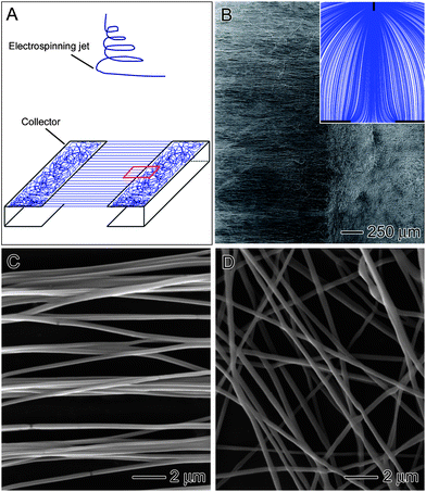
A scaffold with a fiber structure mimetic of the tendon-to-bone insertion site can be readily fabricated by electrospinning through manipulation of the electric field with a unique collector (Fig. 1A). Since the collector is composed of two stapler-shaped metal frames, nanofibers will be deposited in random and aligned orientations on the metal and across the air gap, respectively. Fig. 1B shows SEM image of a typical “aligned-to-random” electrospun nanofiber scaffold. The inset shows a streamline plot of the electric field between the spinneret and the collector, which was obtained using software COMSOL3.3. The electric field pointed directly towards the conductive region. In the vicinity of the collector, the streamlines split into two major branches and developed bending towards two opposite edges of the gap. As a result, the nanofibers would be stretched across the gap to generate a uniaxially aligned array. Fig. 1C and D shows magnified views of the ordered and disordered portions of the sample shown in Fig. 1B. Note that the uniaxially aligned nanofibers could replicate the structural organization of collagen fibers in a native tendon.
 | ||
| Fig. 1 (A) Schematic illustrating the experimental setup for the fabrication of aligned-to-random nanofiber scaffolds. (B) SEM images of nanofiber scaffolds consisting of random and uniaxially aligned PLGA (50 : 50) nanofibers on the left and right, respectively, or the small region of boxed in (A). Inset: streamline plot of electric field between the needle and collector. (C and D) High-magnification views of the random and aligned portions of the scaffold in (B). | ||
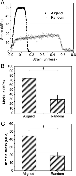
To examine the effect of nanofiber alignment on mechanical properties, random and aligned scaffolds were fabricated separately and tested in uniaxial tension (N = 7–9 per group). Both random and aligned fiber samples were collected using a rotating mandrel in an effort to obtain roughly the same thickness for these two types of scaffolds and thus a better comparison of their mechanical properties. Fig. 2 shows mechanical testing results demonstrating higher modulus and ultimate stress in the aligned scaffolds relative to the random scaffolds. Toughness (the area under the stress–strain curve) was also significantly higher in the aligned scaffolds relative to the random scaffolds (aligned: 142.5 ± 97.9 MPa; random: 52.7 ± 24.2 MPa). These results are consistent with reports from others showing that the mechanical properties of nanofiber scaffolds are highly dependent on the orientation distribution of the nanofibers.5d,12
 | ||
| Fig. 2 (A) Representative stress–strain curves for the aligned and random nanofiber scaffolds. Note that the modulus (B) and ultimate stress (C) were significantly higher for aligned nanofiber scaffolds compared to random counterparts. | ||
To assess the biocompatibility of electrospun PLGA fibers, the proliferation of rat tendon fibroblasts was measured using the MTT assay (data not shown). The tendon fibroblasts were seeded and allowed to proliferate on nanofiber scaffolds of varying compositions over a culture period of 7 days. No significant difference was observed among PLGA scaffolds with different L : G ratios at any particular time point, but significant changes were seen over time for each type of scaffold. To examine the effect of fiber orientation on cell morphology, live cells on either aligned or random fibers were stained with fluorescein diacetate (FDA). Fig. S1† shows fluorescence micrographs, illustrating the morphology of cells seeded on random and aligned scaffolds for 3 and 7 days. After incubation for 3 days, the cells seeded on random fibers had irregular shapes and were randomly oriented. In contrast, the cells seeded on aligned fibers had elongated shapes and were oriented in the direction of fiber alignment. After incubation for 7 days, the cell morphology was similar to what was observed for 3 days but with a higher cell density due to cell proliferation. We quantified cell morphology by calculating the cell shape factor and cell angular orientation for cells seeded on random and aligned scaffolds, respectively. Fig. S2† shows that there was no significant difference in cell shape factor for the cells cultured on random scaffolds compared to the cells cultured on aligned scaffolds after incubation for 3 days. Fig. S3† shows the distribution of cell angles for fibroblasts cultured on random and aligned scaffolds for 3 days. The cells seeded on random fibers had a random angular distribution. In contrast, the cells seeded on aligned fibers showed a significantly narrower angular distribution, indicating that the long axes of the cells were oriented almost in the same direction as the fiber alignment.
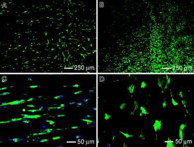
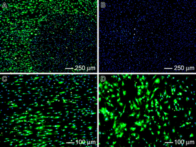
In order to test the responses of tendon fibroblasts to aligned-to-random fiber samples, cells were cultured on the new scaffold containing both aligned and random portions. Double staining with FITC–phalloidin and DAPI was used to elucidate the cytoskeletal arrangement of the tendon fibroblasts. As shown in Fig. 3, the cells responded differently to different portions of the scaffolds. Cells on the aligned portion of each scaffold showed a cytoskeleton consisting of a large number of actin filaments aligned parallel to the long axis of the underlying fibers. In contrast, the cells on the random portion showed a disorganized actin cytoskeleton. These results were consistent with the observations of cell morphology when aligned and random scaffolds were used separately (Fig. S1†). Fig. 3B shows the cell morphology after incubation for 7 days. Again, the results were similar to the observations obtained separately for aligned and random scaffolds (Fig. S1†). To investigate ECM production by the tendon fibroblasts seeded on the fiber scaffolds, immunostaining of collagen types I and II was performed. Collagen type I is the predominant protein in tendon, making up ∼86% of the dry weight of the tissue.1 Collagen type II is the predominant fibrous protein in articular cartilage, and would therefore be undesirable for tendon tissue engineering.13 As shown in Fig. 4, the tendon fibroblasts seeded on both random and aligned portions of the scaffold produced collagen type I and not type II. A comparable level of collagen type I was produced by cells on the aligned portion of the scaffold relative to the random portion. The collagen type I exhibited a high degree organization on aligned portion and a random distribution on the random portion. Expression of collagen type II was not observed on any region of the scaffold. Production of collagen type I without production of collagen type II on the aligned nanofibers would indicate that the fibroblasts in our system are able to produce the appropriate ECM for tendon repair.
 | ||
| Fig. 3 Tendon fibroblast cell morphology on aligned-to-random PLGA (50 : 50) fiber scaffolds: (A and B) after incubation for 3 and 7 days, respectively. (C and D) High-magnification views of (A). In (A), (C) and (D), F-actin and nuclei of the cells were stained with FITC–phalloidin and DAPI, respectively, in green and blue colors. The cells in (B) were stained with FDA in green color. | ||
 | ||
| Fig. 4 Fluorescence micrographs: (A) immunostaining of collagen type I in green and cell nucleus staining with DAPI in blue; (B) immunostaining of collagen type II in red and cell nucleus staining with DAPI in blue; and (C and D) high-magnification views of (A), illustrating immunostaining of collagen type I in green on the aligned and random portions of the scaffold. | ||
Electrospinning is an enabling technique capable of producing fibrous structures that is well-suited for tissue engineering. Significantly, the electrospun nanofibers can be readily aligned into a uniaxial array to mimic the native structure of a tendon. In the present study, PLGA was chosen as the material due to its excellent biocompatibility and ease of manipulation of biodegradation profile (e.g., by changing the L : G ratio). It was previously demonstrated that uniaxially aligned nanofibers could provide contact guidance cues for a variety of different cells, including neurons, fibroblasts, endothelial cells, cardiomyocytes, skeletal muscle cells, and Schwann cells.14 The effects of fiber diameter and orientation on NIH 3T3 fibroblast morphology and proliferation were also examined for electrospun PLGA meshes.14b It was found that cell proliferation was not sensitive to fiber orientation and the aspect ratio increased systematically with increasing degree of fiber orientation. Furthermore, in vitro culture of rabbit conjunctiva fibroblasts was investigated for aligned collagen nanofibers and the fiber alignment was found to control cell orientation and strengthen the interaction between the cell body and the fibers in the longitudinal direction of the fibers.15 More recently, human rotator cuff fibroblasts were tested with PLGA nanofiber scaffolds.5d It was demonstrated that rotator cuff fibroblasts cultured on the aligned scaffolds were stretched along the longitudinal direction of the nanofibers, whereas the cells on the unorganized scaffolds were polygonal and randomly oriented. The results in our present study are in line with these studies. More significantly, we demonstrated the fabrication of “aligned-to-random” scaffolds which could mimic the collagen fiber orientation distribution found at the tendon-to-bone insertion site. Rat tendon fibroblasts exhibited different morphological responses to different portions of the scaffold. The cells were aligned along the direction of fiber alignment on the organized portion of the scaffold while the cells were randomly oriented on the disorganized portion. The cells on both aligned and random portions of each scaffold only produced collagen type I rather than collagen type II. The collagen type I was organized along the direction of fiber alignment on the aligned portion of the scaffold, mimicking native tendon tissue structure. We also demonstrated the fabrication of “aligned-to-random” nanofiber scaffolds with a graded mineral coating (Fig. S4†), which could be used to mimic both composition and structure at the tendon-to-bone insertion site.8 Combined together, we believe electrospun PLGA nanofiber scaffolds could provide a useful platform for repairing the injury at a tendon-to-bone insertion site in conjunction with other therapeutic strategies such as cell therapy, growth factor treatment, and gene delivery. Our future studies will investigate the potential of these scaffolds for healing tendon-to-bone insertion in an in vivo rotator cuff model.
Acknowledgements
This work was supported in part by an NIH musculoskeletal core center grant (1P30AR057235-01), an NSF CAREER award (844607), and start-up funds from Washington University in St Louis. We also express our thanks to the musculoskeletal core center for providing access to the facility.References
- P. Sharma and N. Maffulli, The Surgeon, 2005, 3(5), 309 Search PubMed.
- J. Chen, J. Xu, A. Wang and M. Zheng, Expert Rev. Med. Devices, 2009, 6, 61 Search PubMed.
- L. E. Richardson, J. Dudhia, P. D. Clegg and R. Smith, Trends Biotechnol., 2007, 25, 409 CrossRef CAS.
- L. M. Galatz, C. M. Ball, S. A. Teefey, W. D. Middleton and K. Yamaguchi, J. Bone Jt. Surg., Am. Vol., 2004, 86A, 219 Search PubMed.
- (a) D. L. Butler, N. Juncosa-Melvin, G. P. Boivin, M. T. Galloway, J. T. Shearn, C. Gooch and H. Awad, J. Orthop. Res., 2007, 26, 1; (b) D. L. Butler, N. Juncosa and M. R. Dressler, Annu. Rev. Biomed. Eng., 2004, 6, 303 CrossRef CAS; (c) A. K. S. Chong, A. D. Ang, J. C. H. Goh, J. H. P. Hui, A. Y. T. Lim, E. H. Lee and B. H. Lim, J. Bone Jt. Surg., 2007, 89, 74 Search PubMed; (d) K. L. Moffat, A. S. P. Kwei, J. P. Spalazzi, S. B. Doty, W. N. Levine and H. H. Lu, Tissue Eng. A, 2009, 15, 115 Search PubMed; (e) T. Funakoshi, T. Majima, N. Iwasaki, N. Suenaga, N. Sawaguchi, K. Shimode, A. Minami, K. Harada and S. I. Nishimura, The American Journal of Sports Medicine, 2005, 33, 1193 Search PubMed; (f) S. Yokoya, Y. Mochizuki, Y. Nagata, M. Deie and M. Ochi, The American Journal of Sports Medicine, 2008, 36, 1298 Search PubMed.
- J. Xie, X. Li and Y. Xia, Macromol. Rapid Commun., 2008, 29, 1775 CrossRef CAS.
- M. Sato, M. Maeda, H. Kurosawa, Y. Inoue, Y. Yamauchi and H. Iwase, J. Orthop. Sci., 2000, 5, 256 CrossRef CAS.
- X. Li, J. Xie, L. Justin, X. Yuan, S. Thomopoulos and Y. Xia, Nano Lett., 2009, 9, 2763 CrossRef CAS.
- S. L. Y. Woo, K. N. An, C. B. Frank, G. A. Livesay, C. B. Ma, J. Zeminski, J. S. Wayne and B. S. Myers, Anatomy, Biology and Biomechanics of Tendon and Ligament, in Orthopaedic Basic Science, AAOS, Rosemont, IL, 2nd edn, 2000 Search PubMed.
- T. J. Koob, Comp. Biochem. Physiol., Part A: Mol. Integr. Physiol., 2002, 133, 1171 CrossRef.
- S. Thomopoulos, G. R. Williams, J. A. Gimbel, M. Favata and L. J. Soslowsky, J. Orthop. Res., 2003, 21, 413 CrossRef.
- N. L. Baker, N. L. Nerurkal, J. A. Burdick, D. M. Elliott and R. L. Mauck, J. Biomech. Eng., 2009, 131, 101012 CrossRef.
- A. Atala, R. Lanza, J. Thomson and R. Nerem, Principles of Regenerative Medicine, Academic Press, Burlington, MA, 3rd edn, 2007 Search PubMed.
- (a) J. Xie, M. R. MacEwan, X. Li, S. E. Sakiyama-Elbert and Y. Xia, ACS Nano, 2009, 3, 1151 CrossRef CAS; (b) C. A. Bashur, L. A. Dahlgren and A. S. Goldstein, Biomaterials, 2006, 27, 5681 CrossRef CAS; (c) X. Zhang, C. B. Baoghman and D. L. Kaplan, Biomaterials, 2008, 29, 2217 CrossRef CAS; (d) H. Zong, C. Y. Bien, L. Chung, D. Yin, B. S. Fang, B. Hsiao, E. Chu and E. Entcheva, Biomaterials, 2005, 26, 5330 CrossRef CAS; (e) J. S. Choi, S. J. Lee, G. J. Christ, A. Atala and J. J. Yoo, Biomaterials, 2008, 29, 2899 CrossRef CAS; (f) Y. Chew, R. Mi, A. Hoke and K. W. Leong, Biomaterials, 2008, 29, 653 CrossRef.
- S. Zhong, W. E. Teo, X. Zhu, R. W. Beuerman, S. Ramakrishna and L. Y. L. Yung, J. Biomed. Mater. Res., Part A, 2006, 79a, 456 CrossRef CAS.
Footnote |
| † Electronic supplementary information (ESI) available: Description of materials and methods, fluorescence microscopy images of cell morphology, quantitative analysis of cell morphology and SEM image of pre-mineralized scaffold. See DOI: 10.1039/c0nr00192a |
| This journal is © The Royal Society of Chemistry 2010 |
