Poly(3,4-ethylenedioxythiophene) on self-assembled alkanethiol monolayers for corrosion protection
David
Aradilla
ab,
Denise
Azambuja
*c,
Francesc
Estrany
bd,
José I.
Iribarren
a,
Carlos A.
Ferreira
e and
Carlos
Alemán
*ab
aDepartament d'Enginyeria Química, E. T. S. d'Enginyers Industrials, Universitat Politècnica de Catalunya, Diagonal 647, 08028, Barcelona, Spain. E-mail: carlos.aleman@upc.edu
bCenter for Research in Nano-Engineering, Universitat Politècnica de Catalunya, Campus Sud, Edifici C', C/Pasqual i Vila s/n, Barcelona, E-08028, Spain
cInstitute of Chemistry, Federal University of Rio Grande do Sul, Av. Bento Gonçalves 9500, CEP 91501-970, Porto Alegre, RS, Brazil. E-mail: denise@iq.ufrgs.br
dUnitat de Química Industrial, Escola Universitària d'Enginyeria Tècnica Industrial de Barcelona, Universitat Politècnica de Catalunya, Comte d'Urgell 187, 08036, Barcelona, Spain
eUniversidade Federal do Rio Grande do Sul, DEMAT, Av. Bento Gonçalves, 9500, setor 4, prédio 74, Cep. 91501-970, Porto Alegre, RS, Brazil
First published on 30th August 2011
Abstract
Self-assembled monolayers (SAMs) of octanethiol and dodecanethiol were used to modify the stainless steel substrates for electrodepositing poly(3,4-ethyledioxythiophene) (PEDOT), a well known polythiophene derivative. Although the influence of the alkanethiol monolayers on the morphology and topology of micrometric (thickness: 2.25–2.35 μm) PEDOT films is practically negligible, they increase significantly the ability to store charge and the adherence. In contrast, treated substrates not only enhance the electrochemical properties of ultra-thin PEDOT films (thickness: 150–350 nm) but also affect significantly the thickness, roughness, porosity, morphology and topology. Such changes depend on both the length of the alkyl chain in the alkanethiol and the incubation period used for the preparation of the SAMs. Finally, the protection against corrosion imparted by PEDOT films deposited on treated substrates has been examined and compared with that obtained using PEDOT deposited on bare stainless steel electrodes. Inhibition of the corrosion in a 3.5% NaCl solution was found to be considerably higher when PEDOT is deposited on treated electrodes, which has been attributed, in addition to the barrier effect produced by the SAMs, to the structural changes induced at the first stages of the electropolymerization.
Introduction
Many studies about the preparation and characterization of self-assembled monolayers (SAMs) at solid surfaces to fabricate interfaces with organized structures and well defined composition and thickness have been reported.1Self-assembly of molecular monolayers relies on spontaneous adsorption of a functional reagent from solution onto a surface, and microstructural organization of the adsorbates through the hydrophobic effect or van der Waals interactions. In particular, alkanethiols anchored to Au(111) surfaces have attracted considerable attention because of the strong interaction between the SH headgroup and the surface, providing a better understanding of the structural organization and properties of these layers.2 The electron transfer behavior of SAMs3 also led to the development of new strategies for modifying electrode surfaces aiming at control of their electrochemical processes.4 Electrons can be transferred across an alkanethiol monolayer by a tunneling mechanism, which operates up to ∼12 carbon atoms in the alkyl chain affording electroactive properties to such monolayers.5A field that has received attention in the last fifteen years is the anodic polymerization of conjugated conducting polymers (CPs) on electrodes modified with SAMs to control surface properties and to form stable surface modifications. Specifically, electrochemical oxidation of the corresponding monomers on polycrystalline platinum or gold electrodes coated with long-chain alkanethiols has been used to prepare, among others, polyaniline and some of its derivatives,6–10polypyrrole,6,11,12 polybithiophene,13,14 poly(3-methylthiophene)15–17 and poly(3-octylthiophene).18 In general, results indicated that the preadsorption of alkanethiol monolayers improves the electrochemical and optical properties of the conducting polymers.
Poly(3,4-ethylenedioxythiophene), hereafter abbreviated PEDOT (Scheme 1), is one of the most important CPs due to its high conductivity (up to 500 S cm−1), good environmental and chemical stability, fast doping–dedoping processes and excellent biocompatibility.19–22 Moreover, PEDOT presents excellent electrochemical properties in terms of electroactivity and electrostability, explaining the high ability of this material to store charge (i.e. electrical energy).23–25 In spite of the impressive properties of this CP, to the best of our knowledge, there is a unique study combining both PEDOT and SAMs, even though the latter were not used to modify the electrodes before electropolymerization but the films once generated.26 Specifically, electrochemically grown films of PEDOT and other CPs were treated with alkane- and fluoroalkane-thiols for incubation periods ranging from 1 to 24 h.26 Treatment of the investigated CPs resulted in covalent bonding of the thiol groups to the polymer backbone, even though this effect was to a lesser extent in PEDOT than in PPy and PAni. Furthermore, SAMs deposited onto the PEDOT and PPy films induced a reduction in the electroactivity, while coated PAni retained the electroactivity.
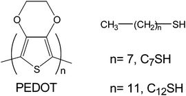 | ||
| Scheme 1 Chemical structures of poly(3,4-ethylenedioxythiophene) and alkanethiols. | ||
The aim of this work is to examine the properties of PEDOT electrodeposited on alkanethiol-coated electrodes. Specifically, the surface of stainless steel substrates, which were successfully used to produce micrometric and nanometric PEDOT films with excellent electrical and electrochemical properties,24,25,27 was treated with octanethiol (C8SH) and dodecanethiol (C12SH). The influence of the two alkanethiols on structural and electrochemical properties of PEDOT films has been examined in detail using X-ray photoelectron spectroscopy (XPS), atomic force microscopy (AFM), scanning electron microscopy (SEM) and cyclic voltammetry (CV). Furthermore, the impact of the SAMs on the corrosion resistance imparted by PEDOT films has been examined using electrochemical impedance spectroscopy (EIS) and SEM. For this purpose, PEDOT coatings electrodeposited on treated and untreated steel sheets were immersed in 3.5% NaCl aqueous solution, electrochemical and morphological changes at the surface of the barrier films being analyzed.
Methods
Chemicals
3,4-Ethylenedioxythiophene (EDOT) monomer, C8SH, C12SH and acetonitrile (analytical reagent grade) were purchased from Aldrich and used as received. LiClO4 (analytical reagent grade) from Aldrich was stored in an oven at 80 °C before use in the electrochemical trials.Monolayers formation
Thiol monolayers were prepared by immersing stainless steel electrodes, which were previously cleaned with acetone, into 50 mL of alkanethiol as received from Aldrich for time τ = 2, 10 or 24 h. Then, the C8SH-steel and C12SH-steel modified electrodes were removed from the solutions, rinsed with acetonitrile and dried with nitrogen.Synthesis
PEDOT was obtained by potentiostatic electropolymerization (chronoamperometry, CA) at 1.40 V (ref. 24) in an acetonitrile solution containing 0.01 M of the corresponding monomer and 0.1 M LiClO4 using polymerization times (θ) of 10 and 300 s. Polymerizations were carried out in a standard three-electrode two-compartment cell under nitrogen atmosphere (99.995% in purity) at 25 °C. Steel AISI 316 sheets of 4 cm2 area (or 1 cm2 for topographic and morphologic analyses; see below) were employed as working and counter electrodes, while the reference electrode was an Ag|AgCl electrode containing a KCl saturated aqueous solution (E0 = 0.222 V at 25 °C). In order to avoid interferences during the electrochemical analyses, the working and counter electrodes were cleaned with acetone and dried in an air-flow before each trial. The thickness of PEDOT films produced using θ = 10 and 300 s was determined to be ∼150 nm (ref. 28) and 2.25–2.35 μm (ref. 29), respectively.Chronoamperometric measurements during the anodic polymerization process were controlled using a VersaStat II potentiostat–galvanostat connected to a computer controlled through a Power Suite Princenton Applied Research program. After electropolymerization, all coated electrodes were cleaned with acetonitrile (generation medium) and dried with nitrogen.
Electrochemical measures
The ability to store charge (electroactivity) and electrochemical stability upon consecutive oxidation–reduction cycles (electrostability) of PEDOT films grown in untreated-, C8SH- and C12SH-steel electrodes were determined by CV using an acetonitrile solution with 0.1 M LiClO4. The initial and final potentials were −0.50 V, while the reversal potential was 1.60 V. The electroactivity increases with the similarity between the anodic and cathodic areas of the first control voltammogram, whereas the electrostability decreases with the oxidation and reduction areas of consecutive control voltammograms. Accordingly, electroactivity and electrostability were determined through direct measure of the anodic and cathodic areas in the control voltammagrams using the Power Suite Princenton Applied Research software. The electrochemical thickness of both nanometric and micrometric PEDOT films was derived from the mass of the polymer deposited in the untreated-, C8SH- and C12SH-steel electrodes, using a previously described procedure.29EIS measurements were performed using an AUTOLAB PGSTAT 30/FRA 2 system in potenciostatic mode at the open circuit potential (OCP). The amplitude of the EIS perturbation signal was 50 mV, and the studied frequency ranged from 103 to 10−3 Hz. Corrosion tests were performed using a 3.5% NaCl solution. All experiments were carried out in air at 25 °C.
Fourier-transform infrared (FTIR)
Spectra were recorded on an FTIR 4100 Jasco spectrophotometer with a resolution of 4 cm−1 in the absorbance mode. The samples were placed in an attenuated total reflection accessory with thermal control and a diamond crystal (Golden Gate Heated Single Reflection Diamond ATR, Specac-Teknokroma).X-Ray photoelectron spectroscopy
Measurements were performed using a SPECS system equipped with an Al anode XR50 source operating at 150 W and a Phoibos 150 MCD-9 detector XP. Samples of 1 cm2 were fixed into the sample holder using double sided carbon tape. The pass energy was set at 25 eV using 0.1 eV steps. The partial pressure of the argon flood gun was below 1.5 × 10⁻⁹ mbar. Data acquisition and processing were achieved with the Advantage Software. Spectral calibration was determined by setting the main C1s component at 285 eV.Atomic force microscopy
Topographic images were obtained with a Molecular Imaging PicoSPM using a NanoScope IV controller in ambient conditions. The tapping mode AFM was operated at constant deflections (i.e. vertical constant force with triangular shaped gold-coated silicon nitride). The row scanning frequency was set to 1 Hz and the physical tip–sample motion speed was 10 μm s−1. The root-mean-square (RMS) roughness (r) was determined using the statistical application of the Nanoscope software, which calculates the average considering all the values recorded in the topographic image with exception of the maximum and the minimum. The scan window size was 5 × 5 μm2 in all cases, a total of 65.536 topographic data being computed in each image. In all images acquired, which are 512 × 512 pixel2 maps, differences in height are indicated by a color scale: dark is low and white is high. Significant searches in different areas of the films were performed to find optimum images. Only reproducible images have been reported in this paper.The thickness of the nanometric PEDOT films generated on the C8SH- and C12SH-steel electrodes was determined using AFM scratch technique. This method is based on the use of AFM topographic measurements to determine the height at the step defined by the substrate–PEDOT interface of films scratched without penetrating the substrate.
Scanning electron microscopy
SEM images were analyzed using a Focused Ion Beam Zeiss Neon40 scanning electron microscope at 3 kV.Adherence
Measurements were based on the standard sellotape test (TESA-4204 BDF), which consists in cutting the film into small squares, sticking the tape and then stripping it. The ratio between the number of adherent film squares remaining and their total number gives the percentage adherence.Results and discussion
Steel-modified electrodes
Fig. 1 compares the height images and transversal section profiles determined by AFM for untreated-, C8SH- and C12SH-steel substrates, the latter two corresponding to an incubation of τ = 24 h in the alkanethiol solution. As it can be seen, the untreated-steel surface is very flat showing a RMS roughness of only r = 11 nm. Deposition of alkanethiols produces significant variations in both the roughness, which is 57 and 27 nm for C8SH- and C12SH-steel, respectively, and topography of the surfaces. Regarding the latter, irregularities are more frequent in C8SH-steel than in C12SH-steel. SAMs produced using the alkanethiol with the largest hydrocarbon chain are more uniform and show fewer structural defects than those made with the shortest one, which should be attributed to the better packing of the former with respect to the latter. Thus, it is well known that long chain alkanethiols CnSH with n ≥ 11 form well-ordered monolayers on surfaces because of the close-packing of the molecules.30,31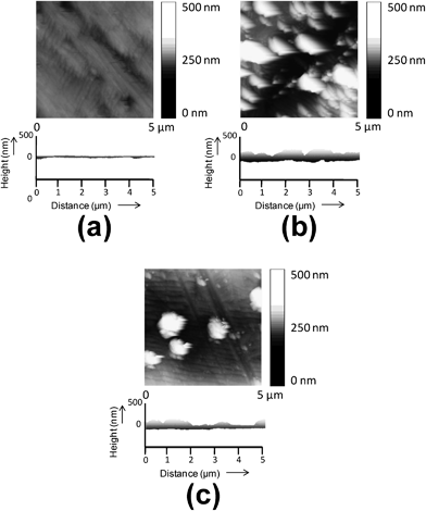 | ||
| Fig. 1 AFM height image and transversal section profile of the substrates used in this work for electrochemical polymerization: (a) untreated-, (b) C8SH- and (c) C12SH-steel. | ||
To characterize the covalent attachment of the thiols to the surface of stainless steel, XPS analyses were performed. Fig. 2a shows the high resolution spectra of the sulfur 2p region for C12SH-steel prepared using τ = 2 h. The S 2p binding energy ranges from 155 to 168 eV. The component at 162.87 eV (S 2p3/2) corresponds to the steel-bound thiolate (S–Fe), whereas the component at 163.90 eV (S 2p1/2) can be assigned to unbound thiol (–SH) or disulfide bonds (S–S).2a,32,33 The formation of SAMs on steel sheets is schematically depicted in Fig. 3.
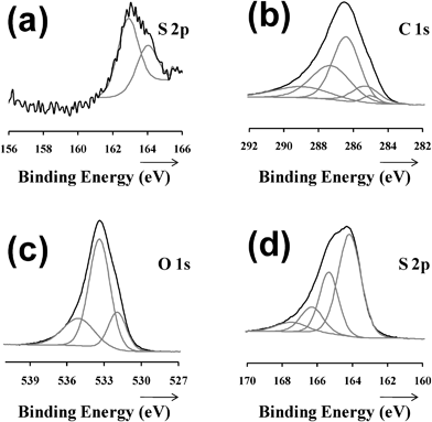 | ||
| Fig. 2 High resolution XPS spectra of the: (a) sulfur 2p region for the C12SH-steel (τ = 2 h) substrate; carbon 1s (b) oxygen 1s (c) and sulfur 2p (d) regions for the PEDOT film deposited on C12SH-steel (τ = 2 h). | ||
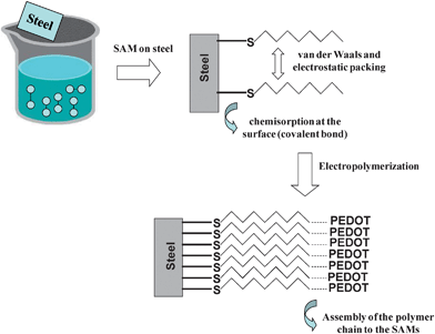 | ||
| Fig. 3 Scheme illustrating the formation of SAMs of alkanethiols and the electropolymerization of PEDOT on modified electrodes. | ||
Micrometric PEDOT films
FTIR analyses (data not shown) indicate that the band centered at 756 cm−1, which corresponds to the Cα–H out-of-plane bending mode, is detected in the spectrum recorded for the pure EDOT monomer but not in the spectra of PEDOT films, independently of both the substrate and θ. This feature reflects that in all cases CA provides linear polymer molecules through the formation of α,α-linkages. Accordingly, electropolymerization of PEDOT using steel electrodes coated with l-alkanethiols was a success in all cases (Fig. 3).AFM and SEM images of micrometric PEDOT films (θ = 300 s) deposited on untreated- and C8SH-steel, where the SAMs of the latter substrate were prepared considering τ = 2 h, are displayed in Fig. 4. The resemblance between the images obtained for the two systems, which in addition are very similar to those recorded from films deposited on C12SH-steel and on modified substrates prepared using τ = 10 and 24 h (data not shown), indicates that influence of the SAMs' interface on the globular morphology is practically negligible when the thickness of the film is within the micrometric scale. Similarly, electrochemical measures indicate that the influence of SAMs on the thickness is negligible, the values obtained for films deposited on C8SH- and C12SH-steel (Fig. 4c) being practically identical to those reported for films on untreated-steel (2.25–2.35 μm),29 independent of τ. In spite of this, the roughness of the films obtained using C8SH- and C12SH-steel increases by ∼22% and ∼30%, respectively, with respect to those generated using untreated steel [e.g. the average RMS roughness for films on untreated-, C8SH- and C12SH-steel (τ = 2 h) is 393, 488 and 524 nm, respectively].
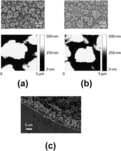 | ||
| Fig. 4 SEM (top) and AFM height (bottom) images of micrometric PEDOT films deposited on (a) untreated- and (b) C8SH-steel substrates. (c) SEM image showing the thickness of the micrometric PEDOT film deposited on C8SH-steel. Films were prepared considering a polymerization time of 300 s (thickness: 2.25–2.35 μm) and the modified substrate was obtained by immersing the steel electrode into 50 mL of octanethiol by τ = 24 h. | ||
High resolution XPS spectra of the C 1s, O 1s, S 2p and Cl 2p regions for PEDOT films obtained using untreated- and C12SH-steel (τ = 2 h) electrodes were carried out to characterize the structure, counterion bonding and composition. The position of the peaks in the spectra was practically identical for both systems, the latter being the only one displayed in Fig. 2. Analysis of the C 1s region (Fig. 2b) evidences four types of carbon, C–C/C–H (285.0 eV), C–S (285.3 eV) in the α position, C![[double bond, length as m-dash]](https://www.rsc.org/images/entities/char_e001.gif) C–O (286.3 eV) in the β position, and C–O–C (287.2 eV) in the ethylene bridge, which is in agreement with the values previously reported.34,35 The carbon spectra also show an asymmetrical tail that resulted from a combination of π–π* shake-up transition and possibly positively polarized or charged carbon.34,36–38 The PEDOT characteristic C–O–C (533.3 eV) bonding is present in the O 1s region (Fig. 2c) as well as a perchlorate (531.9 eV) contribution.39 The PEDOT spin–split sulfur coupling, S 2p3/2 (164.1 eV) and S 2p1/2 (165.3 eV), with a separation of 1.18 eV,40 also presents a higher energy broad tail arising from positively charged sulfur within the thiophene ring (Fig. 2d).41–43 Another sulfur species observed at 166–167 eV have been attributed to oxidized S species, which may be due to fact that samples were repeatedly exposed to the atmosphere since their generation.33
C–O (286.3 eV) in the β position, and C–O–C (287.2 eV) in the ethylene bridge, which is in agreement with the values previously reported.34,35 The carbon spectra also show an asymmetrical tail that resulted from a combination of π–π* shake-up transition and possibly positively polarized or charged carbon.34,36–38 The PEDOT characteristic C–O–C (533.3 eV) bonding is present in the O 1s region (Fig. 2c) as well as a perchlorate (531.9 eV) contribution.39 The PEDOT spin–split sulfur coupling, S 2p3/2 (164.1 eV) and S 2p1/2 (165.3 eV), with a separation of 1.18 eV,40 also presents a higher energy broad tail arising from positively charged sulfur within the thiophene ring (Fig. 2d).41–43 Another sulfur species observed at 166–167 eV have been attributed to oxidized S species, which may be due to fact that samples were repeatedly exposed to the atmosphere since their generation.33
Fig. 5 compares the control voltammograms of micrometric PEDOT films deposited on untreated-, C8SH- and C12SH-steel, the latter two being prepared considering τ = 2, 10 and 24 h. As it can be seen, the electroactivity of films obtained using electrodes pre-treated with alkanethiols was significantly higher than that of PEDOT deposited on untreated-steel. Thus, the ability to store charge increases by ∼20% and ∼30% for C8SH- and C12SH-steel, respectively, even though such enhancement is practically independent of τ. On the other hand, the loss of electroactivity upon 30 consecutive oxidation–reduction cycles is of only 14% for PEDOT films deposited on untreated-steel, whereas the electrostability of films on C8SH- and C12SH-steel largely depends on τ. This is reflected in Fig. 6, which displays the variation of the loss of electroactivity against τ for the two types of pre-treated substrates. In both cases, the loss of electroactivity increases with τ, even though films deposited on C12SH-steel using τ = 2 and 10 h are more electrostable than those on untreated-steel.
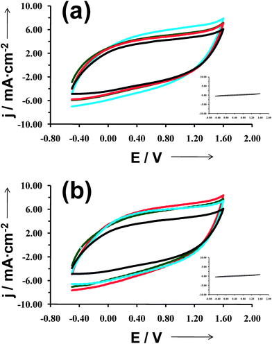 | ||
| Fig. 5 Control voltammograms for the oxidation of micrometric PEDOT films deposited on untreated- (black line in both (a) and (b)), C8SH- (a) and C12SH-steel (b) substrates, the latter two being prepared considering τ = 2 h (blue line), 10 h (green line) and 24 h (red line). Voltammograms were recorded using a 4 cm2 steel electrode in acetonitrile with 0.1 M LiClO4, at 100 mV s−1 and 25 °C. Initial and final potentials: −0.50 V; reversal potential: 1.60 V. The absence of electrochemical activity of uncoated C8SH- and C12SH-steel substrates (blank samples) is evidenced in the insets of (a) and (b), respectively. | ||
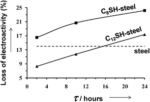 | ||
| Fig. 6 Variation of the loss of electrostability of micrometric PEDOT films after 25 consecutive oxidation–reduction cycles against the period of time in which steel substrates were immersed in alkanethiol solutions (τ). The dashed line indicates the loss of electroactivity for PEDOT deposited on untreated-steel. | ||
The adherence was estimated using a normalized sellotape test, which gives a measure ranging from 0 to 100%. Electrodes modified with SAMs improve the adherence of micrometric PEDOT films. Thus, adherence of PEDOT to the untreated-steel surface is 68% ± 1%, while that of films deposited on C8SH- and C12SH-steel is 75% ± 1% and 83% ± 2%, respectively, independent of τ.
Nanometric PEDOT films
AFM images of nanometric PEDOT films (θ = 10 s) deposited on untreated, C8SH- and C12SH-steel (both τ = 2 and 24 h) are compared in Fig. 7, while the roughness and the thickness of the films are listed in Table 1. As it can be seen, ultra-thin PEDOT films are significantly affected by the pre-treatment of the substrate, the thickness increasing with both the length of the alkyl chain in alkanethiol and τ. Specifically, comparison with the film deposited in untreated-steel indicates that the thickness increases from 16% to 54% and from 74% to 114% when the steel electrode is incubated in C8SH and C12SH solutions, respectively, for τ values ranging from 2 to 24 h.![[small script l]](https://www.rsc.org/images/entities/i_char_e146.gif) ; in nm), roughness (r; in nm) and
; in nm), roughness (r; in nm) and ![[small script l]](https://www.rsc.org/images/entities/i_char_e146.gif) /r ratio of nanometric PEDOT films (θ = 10 s) deposited on untreated and pre-treated steel electrodes. C8SH- and C12SH-steel electrodes were prepared considering τ = 2, 10 and 24 h
/r ratio of nanometric PEDOT films (θ = 10 s) deposited on untreated and pre-treated steel electrodes. C8SH- and C12SH-steel electrodes were prepared considering τ = 2, 10 and 24 h
| Substrate | τ |
![[small script l]](https://www.rsc.org/images/entities/i_char_e146.gif)
|
r |
![[small script l]](https://www.rsc.org/images/entities/i_char_e146.gif) /r /r |
|---|---|---|---|---|
| Steel | — | 153 ± 12 | 67 | 2.3 |
| Steel-C8SH | 2 h | 178 ± 23 | 78 | 2.3 |
| 10 h | 185 ± 28 | 109 | 1.7 | |
| 24 h | 236 ± 19 | 87 | 2.7 | |
| Steel-C12SH | 2 h | 267 ± 31 | 100 | 2.7 |
| 10 h | 308 ± 20 | 91 | 3.4 | |
| 24 h | 343 ± 18 | 93 | 3.7 |
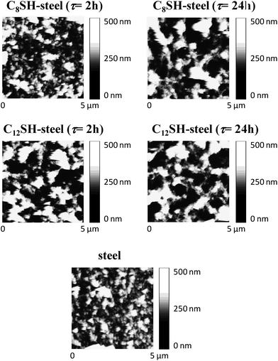 | ||
| Fig. 7 AFM height images of nanometric PEDOT films deposited on untreated-, C8SH-steel and C12SH-steel substrates. Films were prepared considering a polymerization time of 10 s. Pre-treated substrates were obtained by immersing the steel electrodes into 50 mL of alkanethiol by τ = 2 and 24 h. | ||
The influence of the two alkanethiols on both the roughness and the topology is apparently different. Thus, although τ affects considerably both the roughness and topology of the films deposited on C8SH-steel, this effect is less pronounced (topology) or almost inexistent (roughness) in films deposited on C12SH-steel. The high density of small aggregates detected on porous films deposited on untreated-steel transforms into a distribution involving a few compact aggregates upon the pretreatment of the substrate. The dimension (both height and diameter) and the density of such aggregates increases and decreases, respectively, with the size of the alkanethiol and, in the case of the C8SH-steel electrode, with τ. This behavior should be attributed to the fact that SAMs of C12SH are more regular and well-packed than those of C8SH, the influence of the incubation time τ on the structure being much less relevant in the former than in the latter.
Similar features are evidenced in Fig. 8, which shows high- and low-resolution images of PEDOT films deposited on untreated-, C8SH- and C12SH-steel (τ = 2 h). Thus, the porosity of the films clearly grows in the following order: steel ≪ C8SH-steel ≪ C12SH-steel, evidencing that the pre-treatment of the substrates with alkanethiols significantly affects the morphology of the surface.
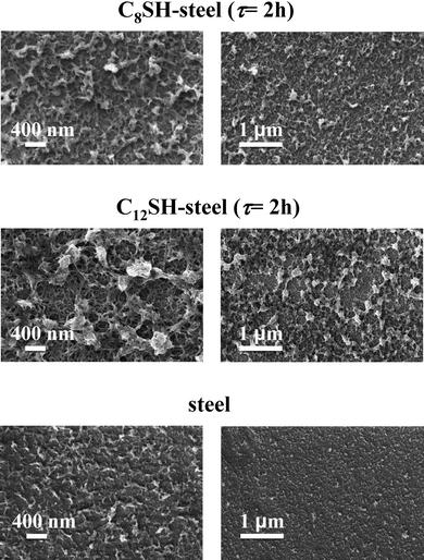 | ||
| Fig. 8 High- and low-resolution SEM micrographs (left and right, respectively) of PEDOT films deposited untreated-, C8SH- and C12SH-steel substrates. Films were prepared considering a polymerization time of 10 s. Pre-treated substrates were obtained by immersing the steel electrodes into 50 mL of octanethiol by τ = 2 h. | ||
The electroactivity and electrostability of nanometric films deposited on C8SH- and C12SH-steel electrodes have been determined, results being expressed in Table 2 relative to those obtained for PEDOT generated on untreated-steel. As it can be seen, the electroactivity and electrostability of PEDOT films produced on the modified substrates are significantly higher than those of the material electropolymerized on untreated-steel. The electroactivity grows with the length of the alkanethiol, the maximum enhancement being achieved with the smallest incubation time in both cases. In contrast, the electrostability is relatively similar in all cases, independent of both the alkanethiol and τ. It should be emphasized that the electroactivity of nanometric and micrometric PEDOT films deposited on modified electrodes is ∼40% and ∼25%, respectively, higher than that of the films generated using untreated-steel. This feature evidences that the role of the alkanethiols is significantly more important in the nanometric scale than in the micrometric one. On the other hand, it should be noted that adherence measurements on films produced using θ = 10 s are not representative due to their ultra-thin nature.
| Substrate | Incubation time (τ) | Electroactivity | Electrostability |
|---|---|---|---|
| Steel-C8SH | 2 h | 39 | 8 |
| 10 h | 36 | 8 | |
| 24 h | 35 | 9 | |
| Steel-C12SH | 2 h | 45 | 6 |
| 10 h | 43 | 7 | |
| 24 h | 41 | 7 |
Corrosion protection
SAMs derived from alkanethiols were successfully applied to inhibit the corrosion of iron and other metallic substrates.44,45 Thus, the formed stable hydrophobic films depressed significantly the metal dissolution of the underlying substrate. On the other hand, PEDOT has been found to impart protection against corrosion when it is used as an anticorrosive additive in the formulation of conventional epoxy paints,46,47 whereas the protective effect of PEDOT films directly deposited on the metal substrate was very slight.48 In this section, we examine the benefits of the alkanethiols in the protective effects of PEDOT films.The EIS plots obtained for PEDOT films (θ = 300 s) deposited on untreated- and C8SH-steel (τ = 2 h) after 24, 168 and 480 h of immersion in a 3.5% NaCl solution are provided in Fig. 9. The EIS diagrams obtained for the films deposited on C8SH- and C12SH-steel were very similar and, therefore, the latter are not reported here for the sake of simplicity. In all cases, spectra show three well-characterized regions. At high frequencies (f > 25 Hz), a capacitive semi-circle related with the polymer–electrolyte interface is observed, its diameter determining the charge transfer resistance (RCT) in parallel with the double layer capacitance (CDL). At intermediate frequencies (25 Hz < f < 1.5 Hz), the spectra show a linear line with a slope around 45°, which corresponds to a Warburg diffusion region and should be attributed to the semi-infinite diffusion of protons at the polymer–electrolyte interface. Finally, at the low frequency range (f < 1 Hz), a nearly vertical line is found due to the faradaic pseudocapacitance of the PEDOT film, as previously described.49,50 Thus, at higher frequencies the process is charge-transfer controlled while at lower frequencies the diffusion of charges in the CP film determines the impedance response. According to Hunter et al.,51 the frequency range of the diffusion behavior is controlled by the diffusion coefficient and the film thickness. Thus, thick films show diffusion over a large frequency range while no diffusion region is detected in ultra-thin films.
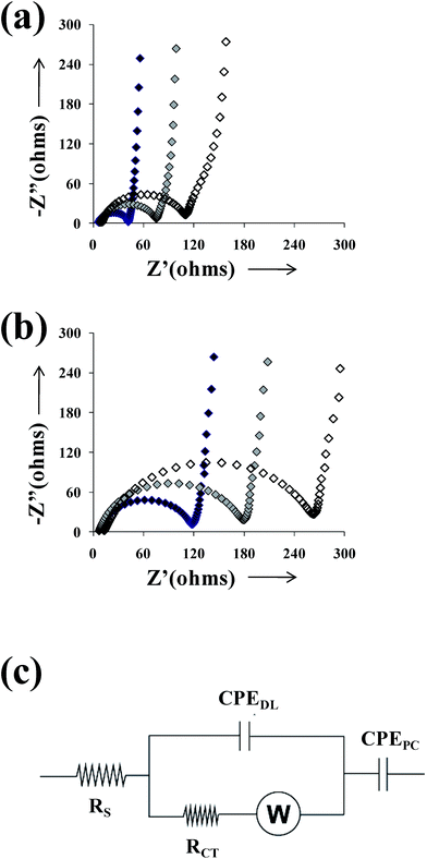 | ||
| Fig. 9 Nyquist plots of PEDOT films deposited on (a) untreated- and (b) C8SH-steel after immersion in a 3.5% NaCl solution for 24 (black symbols), 168 (grey symbols) and 480 h (empty symbols). Films were prepared considering a polymerization time of 300 s. Modified substrates were obtained by immersing the steel electrodes into 50 mL of alkanethiol by τ = 2 h. (c) Equivalent circuit used to simulate the experimental spectra displayed in (a) and (b). | ||
EIS diagrams were analyzed using the equivalent circuit (EC) displayed in Fig. 9c, which was previously proposed for CP coatings.50,52 The proposed EC is given by Rs[CPEDL(RCTW)]CPEPC, where Rs is the ohmic resistance between the working and the reference electrodes; CPEDL is the double layer capacitance; RCT is the charge-transfer resistance in serial connection with a Warburg element, W, that accounts for diffusion; and CPEPC is the pseudo-capacitance at lower frequencies. The capacitances were replaced by a constant phase element (CPE) that describes a non-ideal capacitor when the phase angle is different from −90°. The CPE impedance is attributed to the distributed surface reactivity, surface heterogeneity, and roughness of the current and potential distribution, which are, in turn, related with the electrode geometry and the electrode porosity.53 It should be noted that elements associated with the proposed EC, which was selected considering software limitations and the minimum number of circuit elements, are probably involved on both treated and untreated metal surface. The fitting with experimental data provided error percentage smaller than 5% for each circuit component, indicating a satisfactory behavior.
Table 3 shows the simulated values derived from the fitting of the EIS plots represented in Fig. 9a and b to the EC displayed in Fig. 9c. As it can be seen, the impedance is larger for samples deposited on the C8SH-steel than for those generated on untreated steel. The observed increase of the RCT values at the thiol modified samples was associated with the inhibition effect of thiol layer, decreasing the metal dissolution rate. Moreover, the capacitance associated with this feature (CPEDL) is lower than that of the sample deposited on untreated-steel, remaining practically unchanged during the immersion time, probably due to surface smoothing.54 The Warburg impedance increases with the immersion time, assuming higher values at the samples deposited on C8SH-steel. Additionally, the pores and/or defects of the CP coating can be blocked by corrosion products, making diffusion more difficult and hindering the access of the aggressive electrolyte to the metal surface, which led to an increase of the overall resistance.
| Substrate | Immersion time/h | R S/Ω cm2 | CPEDL/μF cm−2sn−1 | n | R CT/Ω cm2 | W/Ω cm−2 | CPEPC/mF cm−2sn−1 | n |
|---|---|---|---|---|---|---|---|---|
| Untreated-steel | 24 | 7.02 | 15.40 | 0.94 | 33.6 | 12.04 | 20.60 | 0.85 |
| 168 | 9.14 | 20.39 | 0.89 | 68.48 | 22.02 | 20.72 | 0.81 | |
| 480 | 10.41 | 21.73 | 0.86 | 104.4 | 20.53 | 21.05 | 0.95 | |
| C8SH-steel | 24 | 7.96 | 16.81 | 0.91 | 102.1 | 22.17 | 6.17 | 0.80 |
| 168 | 8.16 | 14.70 | 0.88 | 172.9 | 33.26 | 6.79 | 0.79 | |
| 480 | 11.02 | 19.26 | 0.96 | 240.7 | 45.51 | 7.76 | 0.91 |
Fig. 10a shows the surface of the PEDOT film deposited on C8SH-steel after 168 h of immersion in a 3.5% NaCl solution. As it can be seen, aggregates tend to fill the pores at the surface of the CP, making the access of the anions to the substrate difficult. However, the same protection mechanism was also observed in PEDOT films generated on untreated-steel (data not shown). Fig. 10b shows the morphology of both the external and internal sides of the PEDOT film electropolymerized on the C8SH-steel substrate after 480 h of exposure to the 3.5% NaCl solution. The film was washed with distilled water before to obtain the SEM micrographs. As it can be seen, the NaCl does not affect the morphology of the CP, the aspect of the external side being very similar to that displayed in Fig. 4. However, a detailed inspection of Fig. 10b reveals that the morphology of the internal side is more compact than that of the external side. This observation is fully consistent with the results obtained for PEDOT films with nanometric thickness (Fig. 7 and 8). Accordingly, the corrosion protection showed by EIS diagrams (Fig. 9) should be attributed not only to the barrier effect produced by the SAMs of alkanethiol but also to their influence on morphology of the CP at the first stages of the electropolymerization process.
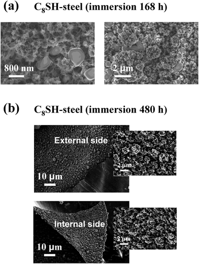 | ||
| Fig. 10 SEM micrographs of the PEDOT film deposited on C8SH-steel: (a) high (right) and low (left) resolution images of the surface after 7 days of exposure to a 3.5% NaCl solution; and (b) the internal and external sides washed with distilled water after 20 days of exposure to a 3.5% NaCl solution. Films were prepared considering a polymerization time of 300 s and the treated substrate was obtained by immersing the steel electrode into 50 mL of octanethiol by τ = 2 h. | ||
Conclusions
SAMs of C8SH and C12SH have been anchored to stainless steel substrates through C–S covalent bonds. A comparison of PEDOT films deposited on untreated-, C8SH- and C12SH-steel reveals that SAMs may affect the structural and electrochemical properties of the CP, even though the scale of such effects depends on the thickness of the films. Specifically, the topology and morphology at the surface of PEDOT films obtained using θ = 300 s, which present thickness larger than 2 μm, are not affected by alkanethiols. However, SAMs promote both the electroactivity and the adherence of micrometric films, such enhancements increasing with the length of alkyl chain of the alkanethiol. In contrast, the influence of SAMs in nanometric PEDOT films, produced using θ = 10 s, is more drastic, affecting the topology, morphology and electrochemical properties of the CP. The extension of such effects depends on the alkanethiol and, in some cases, also on the incubation period τ. Furthermore, SAMs promote the formation of compact molecular aggregates in the first stages of the electropolymerization of PEDOT films. This effect, which produces a reduction of the porosity in the internal side of the films, together with the intrinsic barrier properties of alkanethiol SAMs is responsible for the significant improvement of the abilities of this CP to inhibit corrosion. Thus, EIS experiments showed that PEDOT films deposited on C8SH- and C12SH-steel protect the metallic substrate against corrosion, whereas the protective effect of PEDOT deposited on untreated-steel is considerably lower.Acknowledgements
This work has been supported by MICINN and FEDER funds (MAT2009-09138), by the International Cooperation Program from Brazilian and Spanish Education Ministries CAPES-MICINN (PHB2007-0038-PC), and by the DIUE of the Generalitat de Catalunya (contract number 2009SGR925). Support for the research of C.A. was received through the prize “ICREA Academia” for excellence in research funded by the Generalitat de Catalunya. D.A. thanks the financial support through an FPI-UPC grant.References
- A. Ulman, An Introduction to Ultrathin Organic Films, Academic, New York, 1991 Search PubMed.
- (a) J. C. Love, L. A. Estroiff, J. K. Kriebel, R. G. Nuzzo and G. M. Whitesides, Chem. Rev., 2005, 105, 1103 CrossRef CAS; (b) F. Schreiber, Prog. Surf. Sci., 2000, 65, 151 CrossRef CAS; (c) R. K. Smith, P. A. Lewis and P. S. Weiss, Prog. Surf. Sci., 2004, 75, 1 CrossRef CAS; (d) M. D. Porter, T. B. Bright, D. L. Allara and C. E. D. Chidsey, J. Am. Chem. Soc., 1987, 109, 3559 CrossRef CAS; (e) L. H. Dubois, B. R. Zegarski and R. G. Nuzzo, J. Am. Chem. Soc., 1990, 112, 570 CrossRef CAS.
- A. Becka and C. J. Miller, J. Phys. Chem., 1992, 96, 2657 CrossRef CAS.
- S. K. Allernan, K. Weber and S. E. Creager, J. Phys. Chem., 1996, 100, 17050 CrossRef.
- C. Miller, P. Cuendet and M. Grätzel, J. Phys. Chem., 1991, 95, 877 CrossRef CAS.
- C. N. Sayre and D. M. Collard, Langmuir, 1997, 13, 714 CrossRef CAS.
- C. N. Sayre and D. M. Collard, Synth. Met., 1995, 69, 459 CrossRef.
- M. Mazur and P. Predeep, Polymer, 2005, 46, 1724 CrossRef CAS.
- S. Abaci and C. Shannon, Electrochim. Acta, 2005, 50, 2967 CrossRef CAS.
- L. Niu, R.-M. Latonen, C. Kvarnström and A. Ivaska, Electrochim. Acta, 2004, 49, 4455 CrossRef CAS.
- Z. Meklhalif, P. Lang and F. Gamier, J. Electroanal. Chem., 1995, 399, 61 CrossRef.
- M. Mazur and P. Krusinski, Langmuir, 2000, 16, 7962 CrossRef CAS.
- X. Li, X. Zhang, Q. Sun, W. Lü and H. Li, J. Electroanal. Chem., 2000, 492, 23 CrossRef CAS.
- Z. Mekhalif, J. Delhalle, P. Lang, F. Gamier and J.-J. Pireaux, Synth. Met., 1998, 96, 165 CrossRef CAS.
- D. Gonçalves and E. A. Irene, Electroanalysis, 2003, 15, 652 CrossRef.
- L. F. Rozsnyai and M. S. Wrighton, Chem. Mater., 1996, 8, 309 CrossRef CAS.
- S. Inaoka and D. M. Collard, Langmuir, 1999, 15, 3752 CrossRef CAS.
- M. Mazur and P. Krysinski, J. Phys. Chem. B, 2002, 106, 10349 CrossRef CAS.
- K. Lota, V. Khomenko and E. Frackowiak, J. Phys. Chem. Solids, 2004, 65, 295 CrossRef CAS.
- K. S. Ryu, Y. G. Lee, Y. S. Hong, Y. J. Park, X. L. Wu, K. M. Kim, M. G. Kang, N. G. Park and S. H. Chang, Electrochim. Acta, 2004, 50, 843 CrossRef CAS.
- S. Ghosh and O. Inganas, Electrochem. Solid-State Lett., 1999, 3, 213 CrossRef.
- L. J. del Valle, D. Aradilla, R. Oliver, F. Sepulcre, A. Gamez, E. Armelin, C. Alemán and F. Estrany, Eur. Polym. J., 2007, 43, 2342 CrossRef CAS.
- E. Tamburri, S. Orlanducci, F. Toschi, M. L. Terranova and D. Passeri, Synth. Met., 2009, 159, 406 CrossRef CAS.
- C. Ocampo, R. Oliver, E. Armelin, C. Alemán and F. Estrany, J. Polym. Res., 2005, 13, 193 CrossRef.
- D. Aradilla, F. Estrany and C. Alemán, J. Phys. Chem. C, 2011, 115, 8430 CAS.
- B. Bergman and T. W. Hanks, Macromolecules, 2000, 33, 8035 CrossRef CAS.
- F. Estrany, D. Aradilla, R. Oliver and C. Alemán, Eur. Polym. J., 2008, 44, 1323 CrossRef CAS.
- D. Aradilla, F. Estrany, E. Armelin and C. Alemán, Thin Solid Films, 2010, 518, 4203 CrossRef CAS.
- D. Aradilla, F. Estrany and C. Alemán, J. Appl. Polym. Sci., 2011, 121, 1982 CrossRef CAS.
- C. D. Bain, E. B. Troughton, Y.-T. Tao, J. Evall, G. M. Whitesides and R. G. Nuzzo, J. Am. Chem. Soc., 1989, 111, 329 Search PubMed.
- C. D. Bain and G. M. Whitesides, Science, 1988, 240, 62 CAS.
- W. Deng, L. Yang, D. Fujita, H. Nejoh and C. Bai, Appl. Phys. (Berlin), 2000, 71, 639 CAS.
- R. Desikan, S. Armel, H. M. Meyer, III and T. Thundat, Nanotechnology, 2007, 18, 424028 CrossRef.
- S. K. M. Jönsson, J. Birgerson, X. Crispin, G. Greczynski, W. Osikowicz, A. W. D. Denier Van Der Gon, W. R. Salaneck and M. Fahlman, Synth. Met., 2003, 139, 1 CrossRef.
- S. K. M. Jönsson, M. P. de Jong, L. Groenendaal, W. R. Salaneck and M. Fahlman, J. Phys. Chem. B, 2003, 107, 10793 CrossRef.
- M. A. Khan and S. P. Armes, Langmuir, 2000, 16, 4171 CrossRef CAS.
- J. Riga, P. Snauwaert, A. De Pryck, R. Lazzaroni, J. P. Boutique, J. J. Verbist, J. L. Brédas, J. M. André and C. Taliani, Synth. Met., 1987, 21, 223 CrossRef CAS.
- C. R. Wu, J. O. Nilsson, O. Inganäs, W. R. Salaneck, J. E. Österholm and J. L. Brédas, Synth. Met., 1987, 21, 197 CrossRef CAS.
- S. K. M. Jönssom, W. R. Salaneck and M. Fahlman, J. Mater. Res., 2003, 18, 1219 CrossRef.
- J. F. Moulder, W. F. Stickle, P. E. Sobol and K. D. Bomben, Handbook of X-ray Photoelectron Spectroscopy: a Reference Book of Standard Spectra for Identification and Interpretation of XPS Data, Perkin-Elmer Corporation, Eden Prairie, MN , 1995 Search PubMed.
- G. Greczynski, T. Kugler and W. R. Salaneck, Thin Solid Films, 1999, 354, 129 CrossRef CAS.
- E. T. Kang, K. G. Neoh and K. L. Tan, Phys. Rev. B: Condens. Matter, 1991, 44, 10461 CrossRef CAS.
- G. Zotti, S. Zecchin and G. Schiavon, Macromolecules, 2003, 36, 3337 CrossRef CAS.
- G. Grundmeier, C. Reinartz, M. Rohwerder and M. Stratmann, Electrochim. Acta, 1998, 43, 165 CrossRef CAS.
- M. Itoh, H. Nishiharam and K. Aramaki, J. Electrochem. Soc., 1994, 141, 2018 CrossRef CAS.
- E. Armelin, A. Meneguzzi, C. A. Ferreira and C. Alemán, Surf. Coat. Technol., 2009, 203, 3763 CrossRef CAS.
- E. Armelin, R. Oliver, F. Liesa, J. I. Iribarren, F. Estrany and C. Alemán, Prog. Org. Coat., 2007, 59, 46 CrossRef CAS.
- F. Lallemand, F. Plumier, J. Delhalle and Z. Mekhalif, Appl. Surf. Sci., 2008, 254, 3318 CrossRef CAS.
- W.-C. Chen, T.-C. When, C.-C. Hu and A. Golapan, Electrochim. Acta, 2002, 47, 1305 CrossRef CAS.
- P. Sem and A. De, Electrochim. Acta, 2010, 55, 4677 CrossRef.
- B. Hunter, P. S. Tyler, W. H. Smyrl and H. S. White, J. Electrochem. Soc., 1987, 134, 2198 CrossRef.
- I. Felhosi, J. Telegdi, G. Palinkas and E. Kalman, Electrochim. Acta, 2002, 47, 2335 CrossRef CAS.
- J.-B. Jorcin, M. E. Orazem, N. Pébère and B. Tribollet, Electrochim. Acta, 2006, 51, 1473 CrossRef CAS.
- K. R. L. Castagno, D. S. Azambuja and V. Dalmoro, J. Appl. Electrochem., 2008, 39, 93 CrossRef.
| This journal is © The Royal Society of Chemistry 2011 |
