DOI:
10.1039/C1RA00064K
(Paper)
RSC Adv., 2011,
1, 1078-1082
High temperature powder diffraction study of (Zn,Cd)S and ZnxCd1−xS nanopowders
Received
18th April 2011
, Accepted 17th July 2011
First published on 8th September 2011
Abstract
Nanocrystalline powders of cubic (Zn,Cd)S and ZnxCd1−xS were synthesized by the chemical precipitate method from the aqueous solution of sodium sulphide, zinc nitrate and cadmium nitrate at 277 K without any capping agent. High temperature X-ray diffraction (HTXRD) has been performed to test the stability of the nanopowders. We observed, ZnS is more structurally stable than CdS even at high temperature. The systematic shift in peak position towards the higher angles revealed the changes in the lattice parameter of ZnS and ZnxCd1−xS with an increase in the temperature. The environmental impact on ZnS during HTXRD has also been observed. We observed a significant change in the particle size as the temperature increases. Results of the high resolution transmission electron microscopy (HRTEM) and selected area electron diffraction (SAD) are in accordance with the XRD data.
Introduction
Zinc based ternary compounds are of significant importance for device applications, such as short wavelength emitting laser diodes and light emitting diodes. As thin films, they have shown the possibility of tailoring the band gap.1–3 Furthermore, their electronic band structure and wide range of band gaps, together with a low refractive index, allows intense light transmission and also effective electron transport at high electric fields.4 The interest in Zn based ternaries was of particularly concern with an increasing demand for useful materials for the production of flat panel display, high efficiency electroluminescent and field emission devices.1,2 Bulk ZnS was used as a host lattice of phosphors for applications in cathode ray tubes (CRT) and electroluminescent displays (ELDs). Furthermore, (Zn,Cd)S has long been known as a host material for monochrome and color CRTs since the 1960's. Nanostructured CdS was reported to be used in solar cells5 and recently a CdS/TiO2 nano-bulk composite found an application in hydrogen production from an aqueous electrolyte solution.6 In recent years, synthesis and optical properties of semiconductor quantum dots of ZnS,7 CdS,8,9 PbS,10 CdO11,12 and ZnO13 have attracted much interests because of the well-known quantum confinement effects. The electronic and optical properties of these semiconductor nanoparticles were extensively investigated for a wide variety of applications. Decreasing the particle size, dramatically modifies their electronic and optical properties taking place due to the three-dimensional quantum confinement of electrons and holes.14,15 In addition to the change in the electronic and optical properties, the structural behavior also exhibits changes with a reduction in particle size and temperature.16 Most of the II–VI semiconductors reported have unstable structures at high temperatures. In the course of an investigation into the effect of temperature on the structure of cadmium sulphide, zinc sulphide and zinc–cadmium sulphide, it became necessary to measure the relative amounts of cubic and hexagonal stacking at different temperatures.
In this paper we studied the effect of high temperature on the structural properties of cubic (Zn,Cd)S and ZnxCd1−xS. We took the X-ray diffraction data at various temperatures by heating the sample in a vacuum. This was important for the interpretation of solid state transformations, materials behavior and also certain aspects of the metastable cubic to wurtzite phase transition upon heating. Various kinds of micro and nano-crystalline materials could be characterized by X-ray powder diffraction, including inorganics, organics, drugs, minerals, zeolites, catalysts, metals and ceramics.17–21 In this paper we reported the effect of temperature on the structural stability of (Zn,Cd) S and ZnxCd1−xS nanopowders by performing high temperature XRD under rotary vacuum and in air.
Experimental details
(Zn,Cd)S and ZnxCd1−xS nanopowders were synthesized at 277 K using chemical processes without any capping agent. All the chemicals were of analytical grade and were used without further purification. Appropriate amounts of zinc nitrate hexahydrate [(N2O6Zn.6H2O)] and cadmium nitrate tetrahydrate [(Cd(NO3)2.4H2O)] were used as zinc, and cadmium source respectively, along with sodium sulphide [(Na2S)] as the sulfur source. For (Zn,Cd)S nanopowder solutions containing Cd2+ or Zn2+ were kept at 277 K and then the sodium solution was added drop wise. Zn CdS, solutions containing 90% of zinc and 10% of cadmium were mixed using cold bath at 277 K and then the sodium solution was added drop wise. Uniform magnetic stirring was provided for better atomic diffusion during the length of the reaction. The resulting precipitates were filtered off and washed several times with distilled water. The precipitates were then dried in a hot air oven at 50 °C. The final products were then obtained by crushing the dried precipitate using pestle and mortar.
Bruker's D8 Advance diffractometer with a high temperature attachment in θ–2θ geometry (Cu Kα, 40 kV, 30 mA) was used for X-ray diffraction (XRD) studies. The high temperature stage allowed samples to be measured at tightly controlled temperatures from room temperature to 1600 °C in open air, under vacuum, or in a purge gas atmosphere (Antan Paar HTK 16). Silicon powder was used as a standard to calibrate the instrument for the high temperature stage. Nanopowders were mixed with zapon lacquer to hold it on a platinum strip used as a sample holder cum heater for high temperature XRD, under rotary vacuum. The micrographs and diffraction patterns of the nanopowders were studied using transmission electron microscopy (FEI Tecnai G2 20) operating at 200 kV.
Results and discussion
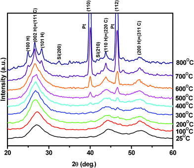
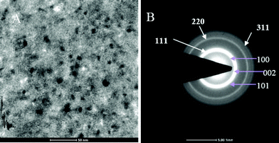
Fig. 1 shows high temperature X-ray diffraction of CdS observed at different temperatures varying from RT to 800 °C. As seen in the figure, the X-ray diffraction recorded at RT shows (111), (220), and (311) characteristic peaks of the cubic phase indexed using standard JCPDS index no. 890440. However, a shoulder of weak intensity corresponding to the (100) peak of wurtzite α-phase (riding over the (111) peak of the β-phase (cubic)) is clearly observed. The presence of Si, used as the standard for the calibration, could also be seen as the (200) and (210) peaks of Si. The (111) peak β-phase CdS shows that the sample was quite stable up to 500 °C and underwent a structural transformation after 500 °C, as shown in Fig. 2. It was due to the deformation stacking fault introduced on alternate close-packed planes of the cubic structure which could be transferred to the hexagonal structure. The mechanism is schematically depicted in Fig. 3. An exact treatment of the broadening of an intensity peak due to stacking fault was the mean of the broadenings of overlapping reflections and moreover, crystallite-size and other effects may intervene. For a precipitate intermediate between the α- and β-CdS the peaks such as (101 H), (100 H) and (002 H) + (111 C) was considered for the calculation. Fig. 2 shows that the sample has much less hexagonal friction (refer to hexagonality ‘ωh’) at room temperature, which increases slightly (almost nil) with an increase in temperature up to 500 °C, and increases rapidly above 500 °C. To find out the hexagonality we applied the assumption of Short and Steward22, using eqn (1) we estimated the transition temperature by the extrapolation of the tangent of the curve.
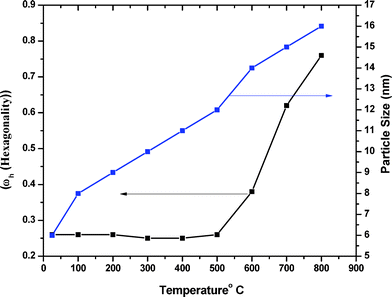 |
| | Fig. 2 Hexagonality and particle size as a function of temperature for CdS. | |
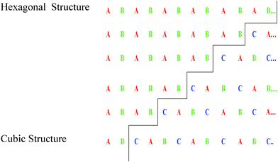 |
| | Fig. 3 Deformation stacking faults on alternate close-packed planes when increasing the temperature of the cadmium sulphide sample. | |
| |
| (1) |
Where
,
Is signifying integrated intensities.
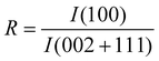
Fig. 2 shows the sizes estimated from Scherrer's formula for the hexagonal and cubic phases using the (002 H) + (111 C) peak.23 For calculating crystallite size we subtracted the instrumental broadening (∼0.1° for microcrystalline Si powder) from the X-ray diffraction data.24 One can note that the particle size calculated as 20 nm from (100) and 14 nm from (101) of hexagonal phase were very different. This suggests that growth in the a–b plane was more favorable than that along the c-axis. This would result in an oblate spheroidal shape of the particle with the shorter dimension being along the c-axis.25 The size of the nanoparticle at room temperature was ∼5 nm, which is in excellent agreement with the TEM observation as shown in Fig. 4. According to Ostwald ripening, the increase in the particle size was due to the merging of the smaller particles into larger ones.26 We observed this increase up to 16 nm at 800 °C.
 |
| | Fig. 4 (A) TEM image showing the 5 nm CdS crystal. (B) TEM diffraction pattern of nano CdS at room temperature. | |
Zinc sulphide (ZnS)
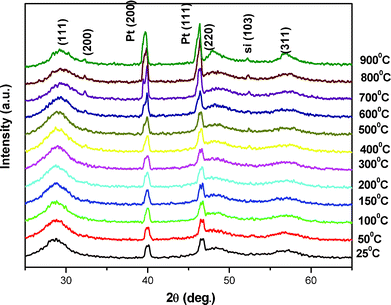
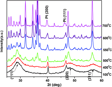
The results of the high temperature X-ray diffraction under rotary vacuum of chemically synthesized ZnS nanoparticles at different temperatures (room temperature to 900 °C) are shown in Fig. 5. All the observed peaks could be indexed to the zinc blende cubic structure (JCPDS index no. 800020). The X-ray diffraction peaks on either side of the ZnS (111) reflection were of the sample holder, i.e.platinum strip. The positions of all the X-ray diffraction peaks remain unchanged, even at high temperatures of 900 °C, revealing the stable structure of ZnS nanoparticles. The X-ray diffraction peak broadening decreased with increasing temperature as expected. However as the temperature reaches above 300 °C another reflection (200) of ZnS began to appear in the X-ray diffraction that became sharper with further rises in temperature. The reason for this, dominant (111) orientation (high energy configuration for the cubic structure) may be attributed to the fact that when the size of the nanoparticles is less than 10 nm then about 10–50% of the atoms were surface atoms. Due to large fraction of these surface atoms, the contribution of surface energy dominated the overall energy of the system that favors the high energy configuration. The increase in temperature provided sufficient energy to the ZnS atoms (grain growth) for bulk diffusion to attain the lower surface energy configuration along the (200) orientation of its cubic structure. High temperature X-ray diffraction (upto 900 °C) for ZnS was also performed in air and is shown in Fig. 6. It was observed that the sample remains in good condition up to 400 °C but due to the highly flammable characteristic of zapon lacquer in air, samples were destroyed at higher temperatures (>400 °C).27
It was interesting to note that there was a gradual shift in peaks position of (111) towards higher 2θ values. It was well known that the lattice parameters are temperature dependent, i.e. an increase in temperature leads to a change in the lattice.28–32 The change in the lattice parameter with an increase in temperature was calculated using the equation  . Where d was the inter-planar distance and a was the lattice parameter (being cubic structure, a = b = c). It was also observed that the shift in (220) peak towards the higher value of 2θ was not significant. It may be due to the location of the stacking fault in the crystal.33 The X-ray diffraction spectra were used to calculate the sizes of the nanoparticles with an increase in temperature using Scherrer's formula. The lattice parameter and particle size, as a function of temperature, are shown in Fig. 7. It is very much evident from Fig. 7 that there was a continuous decrease in the lattice parameter and an increase in particle size with temperature.
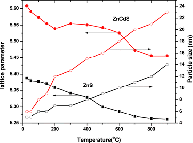 |
| | Fig. 7 The change in lattice parameter and particle size with temperature of ZnS and Zn0.9Cd 0.1S | |
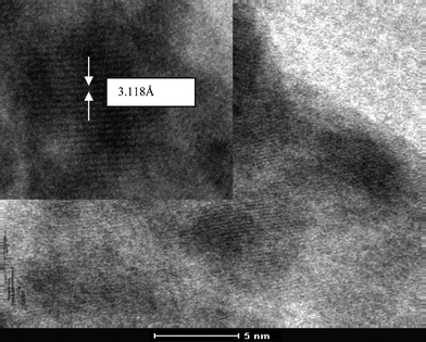
TEM image and the corresponding high resolution image for ZnS nanoparticles are shown in Fig. 8. These images confirm the formation of nanoparticles (∼5 nm) of ZnS, which is in excellent agreement with the X-ray diffraction results.
Zinc cadmium sulphide (ZnxCd1−xS)
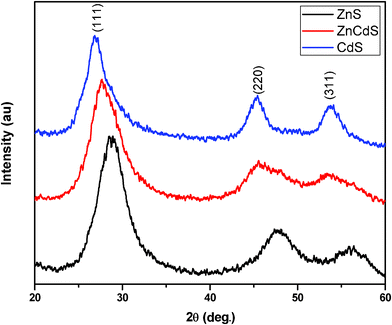
X-Ray diffraction patterns of the samples ZnxCd1−xS are shown in Fig. 9. Three diffraction peaks correspond to the (111), (200) and (311) planes of the cubic crystalline Zn0.9Cd0.1S with reflections positioned at 2θ = 28.10°, 46.07° and 54.11°, respectively. Semiconductor ternaries were proposed to obey Vegard's law, revealing the linear relationship between the lattice constant and composition as follows:34| | 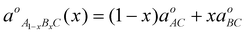 |
(2)
|
where was the natural constant of the ternary form A1−xBxC and a0AC and a0BC were the natural lattice constants of the binaries AC and BC respectively, and x is the mole fraction of binary BC.
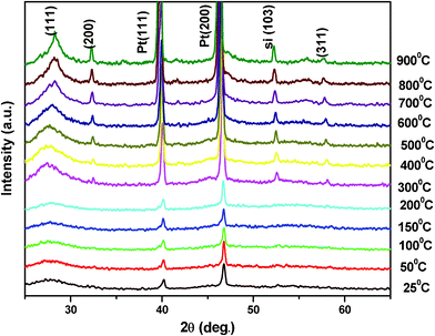
The typical diffraction peak (111) shifted towards the lower angle, as shown in Fig. 9. This shift towards lower angle was believed to result from the incorporation of Cd ions into ZnS lattice at room temperature [PCD index no (241137)]. For high temperature studies of the ZnxCd1−xS system the same procedure also applied. Fig. 10 shows the X-ray diffraction patterns of the ZnxCd1−xS powders at high temperature. Broad diffraction peaks in all the patterns correlated well with the temperature of nanosized materials and shifted towards higher angle, as shown in the case of ZnS. In the ZnxCd1−xS powders we also observed, as the temperature reaches above 300 °C, another reflection (200) began to appear in the X-ray diffraction. Results showed, the X-ray diffraction exhibited a cubic structure of Zn0.9Cd0.1S, which was consistent as ZnS nanoparticles at all stage of temperature. It means a small amount of Cd ions could not much affect the structural stability of ZnS nanoparticle even at high temperature. Lattice parameter and particle size of Zn0.9Cd0.1S also showed the same trend as ZnS on increasing the temperature.
Conclusion
In summary we have observed a structural transformation from cubic (sphalerite) to hexagonal (wurtzite) in the chemically prepared CdS nanopowder after 500 °C, linearly increasing in particle size up 800 °C in a vacuum. The ZnS and ZnxCd1−xS are quite structurally stable at high temperature in a vacuum and in air ZnS gets distorted near 400 °C. We had also studied the variation in lattice parameters of ZnS and ZnxCd1−xS with temperature. A linear decrease in lattice parameters with temperature, along with a increase in the size of the grains, was observed in ZnS and ZnxCd1−xS. Our results have confirmed again that the particle size is strongly dependent on the temperature. A small concentration of Cd ions doesn't have an effect on the structural stability of ZnxCd1−xS.
References
- H. Y. Tang, C. C. Lin, L. S. Wang, K. H. Liao, F. Y. Liao, F. Y. Li and M. Y. Liao, Phys. Rev. B., 2008, 77, 165420 CrossRef.
- A. P. Alivisatos, J. Phys. Chem., 1996, 100, 13226 CrossRef CAS.
- D. J. Norris, Al. L. Efros, M. Rosen and M.G. Bawendi, Phys. Rev. B., 1996, 53, 16347 CrossRef CAS.
- C. G. Rodrigues, Microelectron. J., 2006, 37, 657 CrossRef CAS.
- R. S. Singh, V. K. Rangari, S. Sanagapalli, V. Jayaraman, S. Mahendra and V. P. Singh, Sol. Energy Mater. Sol. Cells, 2004, 82, 315 CrossRef CAS.
- J. S. Jang, S. M. Ji, S. W. Bae, H. C. Son and J. S. Lee, J. Photochem. Photobiol., A, 2007, 188, 112 CrossRef CAS.
- V. T. Liveri, M. Rossi and G. D'Arrigo, Appl. Phys. A: Mater. Sci. Process., 1999, 69, 369 CrossRef CAS.
- M. A. Olshavsky and H. R.Allcock, Chem. Mater., 1997, 9, 1367 CrossRef CAS.
- M. H. Entezari and N. Ghows, Ultraso. Sonochem., 2011, 18, 127 CrossRef CAS.
- A. A. Patel, F. X. Wu and J. Z. Zhang, J. Phys.Chem. B., 2000, 104, 11598 CrossRef CAS.
- A. Askarinejad and A. Morsali, Chem. Eng. J., 2009, 150, 569 CrossRef CAS.
- A. Askarinejad and A. Morsali, Mater. Lett., 2008, 62, 478 CrossRef CAS.
- E. A. Meulenkamp, J. Phys. Chem. B., 1998, 102, 5562 Search PubMed.
- I. Kaur, D. K. Pandya and K. L. Chopra, J. Electrochem. Soc., 1980, 127, 943 CrossRef CAS.
-
K. L. Chopra, R. C. Kahintla, D. K. Pandya and P. ThakoorPhysics of Thin Films12 (New York: Academic) ( 1982) p. 168 Search PubMed.
- S. Ghosh, A. Mukherjee, H. Kim and C. Lee, Mater. Chem. Phys., 2003, 78, 726 CrossRef CAS.
- R. A. Hanna, P. M. Buchler and C. R. Cheeseman, Mater. Sci. Forum, 2005, 498, 740 CrossRef.
- R. J. Bandaranayake, G. W. Wen, J. Y. Lin, H. K. Jiang and C. M. Sorensen, Appl. Phys. Lett., 1995, 67, 831 CrossRef CAS.
-
P. Villars and L. D. Calvert, (eds) Pearson's Handbook of Crystallographic Data for Intermetallic Phases vol 2( 1985) (Metals Park, OH: ASM Internationa) Search PubMed.
- C. C. Chen, A. B. Herhold, C. S. Johnson and A. P. Alivisatos, Science, 1997, 276, 398 CrossRef CAS.
-
A. Guinier
X-Ray Diffraction ( 1963) (San Francisco: Freeman) Search PubMed.
- M. A. Short and E. G. Steward, Am. Min., 1959, 44, 189 CAS.
-
B. D. Cullity and S. R. Stock, ( 2001) 3rd ednPrentice Hall, New Jersey, USA.
- S. Kumar and R. Chandra, Opt. Mater., 2005, 27, 1346 CrossRef CAS.
- S. B. Qadri, E. F. Skelton, D. Hsu, A. D. Dinsmore, J. Yang, H. F. Gray and B. R. Ratna, Phys. Rev. B., 1999, 60, 9191 CrossRef CAS.
- K. K. Nanda, F. E. Kruis and H. Fissan, Phys. Rev. Lett., 2002, 89, 256103 CrossRef CAS.
-
A. report on Safety in Spray Painting
http://www.ilo.org/public/libdoc/ilo/ILO-SR/ILO-SR_Fbis7_engl.pdf
Search PubMed.
- W. H. Qi, M. P. Wang and Y. C. Su, J. Mater. Sci. Lett., 2002, 21, 877 CrossRef CAS.
- W. Qin, Z. H. Chen, P. Y. Huang and Y. H. Zhuang, J. Alloys Compd., 1999, 292, 230 CrossRef CAS.
- Y. Champion, F. Bernard, N. Millot and P. Perriat, Appl. Phys. Lett., 2005, 86, 231914 CrossRef.
- S. Tsunekawa, S. Ito and Y. Kawazoe, Appl. Phys. Lett., 2004, 85, 3845 CrossRef CAS.
- T. J. Klemmer, N. Shukla, C. Liu, X. W. Wu, E. B. Svedberg, O. Mryasov, R. W. Chantrell and D. Weller, Appl. Phys. Lett., 2002, 81, 2220 CrossRef CAS.
- J. D. Makinson, J. S. Lee, S. H. Magner, R. J. De Angelis, W. N. Weins and A. S. Hieronymus, Advances in X-ray Analysis, 2000, 42, 407 CAS.
-
J. Singh, Optoelectronics: An Introduction to Materials and Devices, Macgraw Hill, New Delhi, 1996 Search PubMed.
|
| This journal is © The Royal Society of Chemistry 2011 |
Click here to see how this site uses Cookies. View our privacy policy here.