Study on formation mechanism and ligand-directed architectural control of nanoparticles composed of Bi, Sb and Te: towards one-pot synthesis of ternary (Bi,Sb)2Te3 nanobuilding blocks†
Nguyen T.
Mai
,
Derrick
Mott
,
Nguyen T. B.
Thuy
,
Issey
Osaka
and
Shinya
Maenosono
*
School of Materials Science, Japan Advanced Institute of Science and Technology (JAIST), 1-1 Asahidai, Nomi, 923-1292, Japan. E-mail: shinya@jaist.ac.jp; Fax: +81-761-51-1625; Tel: +81-761-51-1611
First published on 14th September 2011
Abstract
This paper reports a study on the formation mechanism of nanoparticles (NPs) composed of bismuth, antimony and tellurium for thermoelectric materials using a modified polyol synthetic route. Our one-pot synthesis technique has proven highly versatile in creating a wide range of different anisotropic NPs such as nanowires (NWs), nanodiscs (NDs), nanoribbons and nanospines (NDs studded on NWs) simply by modifying the capping species or elemental precursor feeding ratio used in the synthesis. However, an independent control of morphology and composition is still hugely challenging and the facile synthesis of (Bi,Sb)2Te3 solid solution NPs is not a trivial task, reflecting the complex nature of this multicomponent system. To achieve this goal, it is imperative to understand the formation mechanism based on a systematic investigation of mono- and binary elemental NP systems. Our study clearly shows the different actions of oleylamine (OAM) and decanethiol (DT) capping ligands in our synthesis reaction. In the case of DT capping system, Te NDs are first formed, and then, Bi and Sb are separately incorporated into the Te ND structure viacatalytic decomposition of Bi-DT and Sb-DT complexes on the Te ND surfaces. Therefore, the resulting NPs are phase segregated into Te, Bi2Te3 and Sb2Te3. On the other hand, in the case of the OAM capping system, Te NWs and Bi-Sb solid solution NPs are formed separately, and then, parts of Te NWs are transformed into (Bi,Sb)2Te3 phase via oriented attachment of Bi-Sb NPs and Te NWs. These findings are crucially important towards the one-pot synthesis of uniform (Bi,Sb)2Te3 nanobuilding blocks with controllable characteristics for highly efficient thermoelectric materials.
Introduction
With the advent of nanotechnology the field of thermoelectric (TE) materials has been rejuvenated, and what was once thought of as an area of research with insurmountable challenges has now become one of the most promising technologies to extend our current energy sources.1TE materials are highly exciting because they exhibit the Seebeck effect which can be used to create devices that harvest excess heat to create electricity, or can be used to make freonless refrigerators, cool microelectronics, etc.1,2Nanoparticles (NPs) have proven useful in these materials because the small particle (grain) size causes scattering of the heat carrying phonon along the crystal boundaries, effectively allowing the thermal conductivity to be reduced while maintaining the electrical conductivity.2,3 In addition, it has been demonstrated that the NP shape plays a key role in this effect because the orientation and area of the grain boundaries can be tuned by long range ordering of the NPs, for example superlattices of one-dimensional nanowires (NWs) or two-dimensional nanodiscs (NDs).4–6 This causes the overall efficiency of the material to be increased, which is expressed by the dimensionless figure of merit, ZT = α2σT/κ, where α is the Seebeck coefficient, σ is the electrical conductivity, κ is the thermal conductivity and T is the absolute temperature.1 With this in mind, several researchers have attempted to create efficient TE materials with nanostructuring. Bi-Te alloy systems are known to have some of the highest ZT values at low temperature range (< 600 K).2 By creating Bi-Te alloy based NPs, the thermoelectric efficiency is predicted to be even higher.3,7,8Currently there is a large amount of attention being devoted to the creation of nanostructured TE materials. Most often, the synthetic approaches to the TE nanomaterials include techniques such as hydrothermal,9electrochemical deposition,10–13pulsed laser deposition,14sputtering,15 shear extrusion,16 mechanical alloying,17spark plasma sintering,18 rapid solidification processes,19 microwave assisted organic surfactant synthesis,20,21 or sonoelectrochemistry.22 Despite much attention being given to the creation of the nanostructured TE materials, few techniques have proven successful at the creation of true nanoscale particles with controllable size, shape and composition composed of Bi-Te alloys. In response to the challenges encountered in these preparation techniques, a few researchers have begun to explore wet chemical based synthesis techniques towards binary Bi-Te alloy NPs with controllable properties in terms of size, shape, composition, etc. For example, the synthesis of well-defined Bi2Te3-Te heterogeneous nanostructures by controlling the kinetic reaction of Bi3+ and TeO32− in the presence of hydrazine,23 the inorganic surfactant assisted solvothermal synthesis of Bi2Te3 nanoplates,24 the ligand-directed synthesis of Bi2Te3 nanorods or nanosheets,25 or the hot injection synthesis of Bi2Te3 nanoplatelets in the presence of oleic acid26 have been previously reported. Moreover, the synthesis of Bi2Te3 NPs through a microemulsion synthetic route,27 two-step synthesis of Bi2Te3 NPs from Bi seeds in the presence of oleylamine,28hydrothermal synthesis of Bi2Te3 NWs through the solid state interdiffusion of Bi and Te,29surfactant directed synthesis of Bi2Te3/Bi2S3 core–shell nanorods,30 and two-step synthesis of well-defined Bi2Te3 nanotubes based on solution phase nanoscale Kirkendall effect31 have illustrated the feasibility of using chemically synthesized NPs to create materials with enhanced TE properties because of the highly controllable characteristics of the NPs.
The (Bi,Sb)2Te3 ternary solid solution system is known as a p-type TE material and has a higher ZT value when compared with the Bi2Te3 binary alloy.32,33 This is mainly because (Bi,Sb)2Te3 exhibits significantly reduced lattice thermal conductivity due to increased unit cell size, low crystal symmetry, and site occupancy disorder. As stated above, chemical synthesis strategies for binary Bi2Te3 NPs have been somewhat successful, even though the formation mechanisms of those NPs have not been completely clarified yet. Meanwhile, however, there have been very few successful reports on the direct chemical synthesis of (Bi,Sb)2Te3 ternary solid solution NPs. For example, Talapin and co-workers have reported the formation of a Bi2−xSbxTe3 nanostructured thin film by annealingBi2S3 nanorods functionalized with Sb2Te3 metal chalcogenide complex.3 Zhao and co-workers synthesized nanocrystalline Bi-Sb-Te bulk solids by a combination of hydrothermal synthesis and hot pressing.9 Ren and co-workers created irregular-shaped (Bi,Sb)2Te3 bulk solids in an aqueous-phase reduction process.34 All of these synthetic approaches did not lead to isolated (Bi,Sb)2Te3 ternary solid solution NPs. Exceptionally, Burda and co-workers successfully synthesized isolated Bi0.5Sb1.5Te3 angular shaped NPs by direct chemical solution synthesis. They first heated bismuth acetate [Bi(OAc)3] and antimony acetate [Sb(OAc)3] dissolved in phenylether in the presence of dodecanethiol (DDT) for 1 h followed by injection of Te dissolved in trioctylphosphine (TOP), followed by reaction for 30 min to form Bi0.5Sb1.5Te3 NPs.35 Weller and co-workers also reported the successful synthesis of isolated BixSb2−xTe3 nanoplatelets36 which was similar to the synthetic route of Burda and co-workers.35 They first heated Bi(OAc)3 and Sb(OAc)3 dissolved in DDT for 45 min followed by injection of oleylamine and Te dissolved in TOP to form BixSb2−xTe3 nanoplatelets.
The above mentioned synthetic techniques typically required multiple steps with the preparation of elemental precursors and lead to only one specific type of NP in terms of shape or structure, making these approaches very limited in the range of NPs they can produce. The polyol synthetic technique is one that has proven very versatile for synthesizing NPs with controllable size, shape, composition, and structure, and in our own research we have demonstrated that in a one-pot synthesis, this general approach can lead to a wide variety of Bi, Sb and Te based NPs with tunable shape and composition simply by changing the nature of the capping species used in the synthesis.37 Because of the importance in synthesizing (Bi,Sb)2Te3 ternary solid solution NPs with controllable characteristics we present here a study on the formation mechanism of these promising nanoscale materials. The complexity associated with the formation mechanism of NPs is remarkably increased with the presence of more than one elemental precursor and capping ligand. Even in the single elemental system, the growth mechanism was reported to be not simply based on the function of surfactant as a soft template for NP growth.38 Expanding to the double elemental NPs, not only the effect of surfactant but many other factors such as the relative reaction rate or the interaction of the two elemental precursors should be taken into account for the increased difficulties in elucidating the NP formation pathway.39–42 Therefore, in a ternary system, there are many more challenges in addressing the formation mechanism without understanding the fundamental formation of mono- and bi-elemental NPs. Our synthesized NPs consist of Bi, Sb and Te, which are in general considered to be a poor metal (Bi) or a semi-metal (Sb and Te) but hereafter are referred to as “metals”. Hence, a systematic study of mono-, bi- and trimetallic NP synthesis is strongly required to investigate the formation mechanism in this complex system. Our results detail the effect of capping ligands, precursors and the metal–ligand cross interaction on NP morphology and composition and elucidate the different formation mechanisms that occur with different capping species. The formation and synthesis of a ternary BiSbTe NW alloy in oleylamine and binary BiTe/SbTe NDs in decanethiol will be discussed.
Experimental section
Chemicals
Bismuth trichloride (BiCl3, purity 99%), antimony trichloride (SbCl3, purity 99%), tellurium tetrachloride (TeCl4, purity 99%), oleic acid (OAC, purity 90%), oleylamine (OAM, purity 70%), 1,2-hexadecanediol (HDD, purity 90%), 1-decanethiol (DT, purity 96%), 1-dodecanethiol (DDT, purity 98%) and dioctylether (purity 99%) were purchased from Sigma Aldrich Corp. as well as other common solvents. All reagents were used without further purification.Synthesis of NPs
1.67×10⁻⁴ moles each of BiCl3, SbCl3 and TeCl4 precursors were used in the monometallic synthesis. For each bimetallic and trimetallic synthesis, a total 5×10⁻⁴ moles of elemental precursor was used with equimolar feeding ratio. Elemental precursors were mixed with 25 mL of dioctylether, and 1.5×10⁻³ moles of HDD was added along with the capping species, the identity of which was used to manipulate the morphology and composition of the resulting NPs. In this work, OAM, OAC/OAM and DT were used as capping agents with varying ratios and amounts. The exact amount of capping species used in each synthesis is described more fully in the text. Next, the mixture was purged with argon under vigorous stirring. At this point the reaction temperature was raised to 105 °C for 10 min to remove water, which also caused the reactants to completely dissolve in the solvent (a light grey color in the solution). After this, the temperature was increased to 200 °C and was held for 1 h. The formation of particles within this time was evidenced by the solution color change from light grey to dark grey or black depending on the capping species used. After reaction, the NP solution was cooled to room temperature and the particles were purified by precipitation in ethanol. The materials could be briefly resuspended in hexane with additional OAC, OAM and/or DT. The resulting NPs were then analyzed.Instrumentation and analysis conditions
An array of instrumental techniques including X-ray diffraction (XRD), transmission electron microscopy (TEM), energy dispersive spectroscopy (EDS), inductively coupled plasma mass spectroscopy (ICP-MS), electrospray ionization Fourier transform ionization cyclotron resonance mass spectroscopy (ESI-FTICR-MS), and thermogravimetry (TG) were used to characterize the size, shape, composition, structure and other properties of the materials. XRD patterns were collected in reflection geometry using a Rigaku RINT2500 X-Ray diffractometer at room temperature with Cu Kα radiation (wavelength 1.542 Å). TEM analysis was performed on Hitachi H-7100 and H-7650 transmission electron microscopes operated at 100 kV. TEM samples were prepared by dropping the suspended particles onto a carbon coated copper grid and drying in air overnight. Samples for ICP-MS were prepared by dissolving in aqua regia then were diluted using nitric acid solution (2–5%). The data were collected using a Hitachi Plasma Mass Spectrometer P-5000 with guide voltages of 30, 35, and 50 V for Sb, Te, and Bi isotopes, respectively. A Fourier transform ion cyclotron resonance mass spectrometer equipped with a 9.4 T superconducting magnet (SolariX, Bruker Daltonics) was used to analyze the metal–ligand complex solution. TG analysis was performed using a Seiko TG/DTA6200. Samples underwent heat treatment from 25 to 600 °C in flowing nitrogen gas with a heating rate of 10 °C per minute.Results and discussion
In the previous work,37 we successfully synthesized NPs composed of Bi, Sb and Te using different capping systems and the complexity that arose in the ternary alloy system inspired us to conduct a more systematic study to investigate the formation mechanism for controlling the morphology and composition of the final NPs. In this study, three capping systems consisting of OAM, OAC/OAM and DT were used to synthesize mono-, bi- and trimetallic NPs. We studied the effect of individual interactions between capping ligands and metal precursors on NP morphology and composition from the results of the primary synthesis using only one metal precursor with each capping system. Then the combination of two metal precursors was studied to clarify the role that each metal plays in the synthesis, along with effect of capping ligands in the reaction/incorporation of the two metals into the final NPs. These results together with the characterization of trimetallic NPs synthesized using each capping system help to clarify the formation mechanism of trimetallic NPs in these complex systems. As a result of the wide range of syntheses conducted with varying reaction conditions, not all of the synthesized materials have an ideal size, structure or composition. Many of the results related in this work show the formation of micro-sized particles, non-homogeneous structure/composition, or oxidized materials, etc., however these results still shed light on the underlying formation mechanism of NPs in this system. Additionally, it is also important to note that the three different capping ligands used in this study were not further purified before use, so a significant portion of these ligands (especially OAM) may include short alkane chain impurities. It is well known that trioctylphosphine oxide (TOPO) ligands contain impurities such as phosphonates and phosphonic acid, and these impurities may very well bind far more strongly to cation sites than TOPO. The ligands used in this study may also contain impurities which have different functional groups. While these impurities may influence the particle size or shape formation, this study primarily focuses on the chemical nature of the reactive terminus of the primary component of the ligands (i.e.amine, carboxylate and thiol), which is the primary factor leading to the various particle size, morphology, structure and compositions observed.Study of monometallic synthesis approach
Bi, Sb and Te monometallic NPs were synthesized using a single metal precursor with the various capping systems. The morphology and crystal structure of the resulting NPs were characterized by TEM and XRD analyses. The results are briefly summarized in Table 1.| Metal Precursors | Organic Capping Ligands | ||
|---|---|---|---|
| OAM | OAC/OAM | DT | |
| a D and L represent mean diameter and length estimated from TEM images, respectively | |||
| BiCl3 | BiOCl aggregates | BiOCl aggregates | Bi plates |
| D ~ 500 nm | |||
| L > 2 μm | |||
| SbCl3 | Sb NWs | Sb NWs | No solid product |
| D ~ 100 nm | D ~ 100 nm | ||
| L ~ 2−10 μm | L ~ 2−10 μm | ||
| TeCl4 | Te NWs | Te NWs | Te nanoplates |
| D ~ 200 nm | D ~ 100 nm | D ~ 100 nm | |
| L ~ 5−10 μm | L ~ 2−6 μm | ||
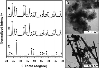 | ||
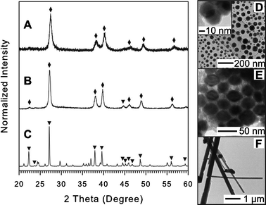
| Fig. 1 XRD patterns and TEM images of materials synthesized using OAM (A and D), OAC/OAM (B), and DT (C and E). The indexed peaks are marked by the symbols open triangle (▽) for BiOCl (JCPDS card no. 006-0242) and filled triangle (▼) for Bi (JCPDS card no. 044-1246). For detailed peak position and assignment see ESI,† Table S1–S3. | ||
Changing to the DT capping system, only an elemental Bi phase was observed with some minor unidentifiable peaks (unlabeled) in the XRD pattern as shown in Fig. 1C. These minor peaks could arise as a result of some leftover bismuth precursor-ligand complex which could not be removed during the particle purification process. A mixture of elongated plate-like particles (∼500 nm in diameter and several microns in length) and smaller polyhedral shaped particles (∼500 nm) are shown in Fig. 1E. These results suggest that DT makes stable complexes with the Bi cation and protect it from creating BiOCl while OAC and OAM ligands do not.
 | ||
| Fig. 2 XRD patterns and TEM images of Sb NWs synthesized using OAM (A and C) and OAC/OAM (B and D). In the case of using DT, no solid particles can be obtained. The upright filled triangles (▲) indicate peaks assigned to Sb with rhombohedral structure (JCPDS card no. 01-085-1322) in the XRD pattern (A and B) (for detail see ESI,† Table S4 and S5). | ||
In a separate experiment, SbCl3 could be dissolved in DT and hexane solvent at room temperature (ESI,† Fig. S3) and ESI-FTICR-MS was used to detect high molecular weight fragments containing Sb isotopes coupled with an organic component which arises from the Sb-DT complex (ESI,† Fig. S4). Moreover, thermal analysis for the Sb-DT complex shows a slow mass loss taking place before 220 °C (ESI,† Fig. S5) which explains the stability of the Sb-DT complex under the reaction conditions. The study of monometallic Sb synthesis suggests that different capping ligands created a complex with Sb with different stability in which DT makes a more stable complex that did not undergo the reduction to Sb NPs while OAM or OAC/OAM creates a weaker complex that can be reduced to form elemental Sb NWs.
 | ||
| Fig. 3 XRD pattern and TEM images of resulting NPs synthesized using OAM (A and D), OAC/OAM (B and E), and DT (C and F). The XRD peaks are labeled by filled circle (●) for hexagonal structured Te (JCPDS card no. 036-1452). For detail, see ESI,† Table S6–S8. | ||
Changing the capping ligand to DT resulted in roughly spherical particles with a diameter of ∼100 nm (Fig. 3F). However, the mean crystalline size of Te NPs was estimated to be around 41 nm from the full width at half-maximum of the (101) primary peak by the Scherrer formula, which is smaller than the size estimated from TEM images (ca. > 100 nm) suggesting that the NPs have a platelet morphology. For detailed XRD peak assignment, see ESI,† Table S8.
Study of bimetallic synthesis approach
To further study the general synthetic system, the analysis was expanded to include binary metallic precursors in the synthesis under otherwise identical conditions to the monometallic cases. The resulting variation in particle formation in terms of composition, morphology and structure reveals the complex nature of this system. The understanding of the interdependence of each metal precursor along with the organic capping ligands is important for controlling the properties of the resulting NPs. Each combination of two elemental precursors was used with different capping ligand systems including OAM, OAC/OAM or DT to study the effect on the final particle characteristics. The general results for these syntheses are summarized in Table 2.| Metal precursors | Organic capping Ligands | ||
|---|---|---|---|
| OAM | OAC/OAM | DT | |
| a The composition assessment is based on EDS except for the case of NPs synthesized using Sb and Te precursors. D, L and H represent mean diameter, length and/or thickness estimated from TEM images, respectively. | |||
| BiCl3, SbCl3 | BiSb nanoplates | BiSb NPs | Bi plates |
| D ~ 20−60 nm | D ~ 20−40 nm | D ~ 100−300 nm | |
| L ~ 10 μm | |||
| BiCl3, TeCl4 | Te NWs | Te NWs | Bi-Te NDs |
| D ~ 30−200 nm | D ~ 100−200 nm | D ~ 30−50 nm | |
| L ~ 3−10 μm | L ~ 3−10 μm | H ~ 5−10 nm | |
| SbCl3, TeCl4 | Te NWs | Te NWs | Sb-Te plates |
| D ~ 30−100 nm | D ~ 50−200 nm | ||
| L ~ 3−10 μm | L ~ 3−10 μm | ||
 | (1) |
 | ||
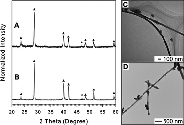
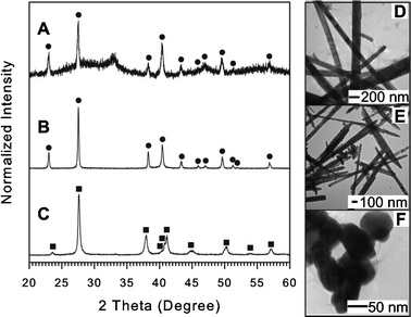
| Fig. 4 XRD patterns and TEM images for Bi-Sb NPs synthesized using OAM (A and D), OAC/OAM (B and E), and DT (C and F). The identities of XRD peaks were labelled by filled diamond (♦) for Bi-Sb alloy (JCPDS card no. 00-035-0517) and filled triangle (▼) for Bi (JCPDS card no. 044-1246). For detail see ESI,† Table S9–S11. | ||
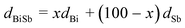
| Metal Precursors | Capping systems | Main product | 2 Theta (deg) | D XRD (nm) | D TEM (nm) |
|---|---|---|---|---|---|
| a D XRD and DTEM represent mean crystalline size and NP size estimated from XRD patterns and TEM images, respectively. | |||||
| TeCl4 | DT | Te nanoplates | 27.54 | 40.9 | ∼100 |
| BiCl3, SbCl3 | OAM | BiSb nanoplates | 27.45 | 14.6 | 39±14 |
| BiCl3, SbCl3 | OAC/OAM | BiSb NPs | 27.28 | 19.0 | 32±4 |
| BiCl3, TeCl4 | DT | BiTe NDs | 27.62 | 43.1 | ∼30–50 |
| SbCl3, TeCl4 | DT | SbTe plates | 28.20 | 45.5 | N/A |
The formation of Bi-Sb solid solution NPs using OAM or OAC/OAM as capping systems without BiOCl suggests a bimetallic interaction in which Sb was first reduced, and then, Sb nuclei effectively catalyzed the decomposition and reduction of Bi precursor and/or Bi-ligand complex to form Bi-Sb solid solution NPs in light of the fact that BiOCl was a main product in the case of Bi monometallic synthesis (Fig. 1). In addition, the Bi-Sb NPs synthesized with the OAM capping system has a two-dimensional nanoplate shape while the NPs obtained in the Sb monometallic synthesis with the same capping system are one-dimensional NWs (Fig. 2C). This result indicates that the preferential growth directions of Bi-Sb and Sb are different from each other in the presence of the same capping ligand, OAM in this case.
On the other hand, the small spherical Bi-Sb NPs formed in the case of the OAC/OAM capping system can be explained based on the improvement in the protecting ability of the double capping system. In combination, OAC and OAM were found to form the carboxylate anion with higher electron donating ability which is likely to result in a stronger interaction with the NP surface.46 As a consequence of this stronger protection, the size of NPs becomes smaller as is the case in the Bi monometallic synthesis (small Bi NPs, see Fig. 1D). In addition, the lack of oxide and BiOCl peaks and the high Bi content in the NP composition in this case may arise as a result of the additional effect of Sb complex as a water scavenger due to the strong interaction of Sb with O in water,47 effectively suppressing the formation of BiOCl. Furthermore, the adsorption and reduction of Bi complex at the Sb surface would explain the formation of Bi rich NPs instead of Sb NWs which were observed in the Sb monometallic synthesis using OAC/OAM.
Changing the capping ligand to DT, particles with elongated plate-like shape occur with a length of ∼10 μm and diameter of ca. ∼100–300 nm, along with some smaller spherical shaped NPs as shown in Fig. 4F. The XRD pattern reveals the formation of elemental Bi with some minor unidentifiable peaks as shown in Fig. 4C, which are characteristically the same pattern as those observed in Fig. 1C for monometallic Bi synthesized using DT (for detailed comparison see ESI,† Fig. S8). Therefore, these unidentifiable peaks could arise as a result of some by-product of bismuth and organic ligand that could not be removed in the particle purification process. One important observation is that there is no bismuth oxide or BiOCl peaks observed in the XRD pattern, which is consistent with the case of Bi monometallic synthesis using DT. The composition assessment using EDS shows only Bi without Sb in the final products. These results show the consistence with the monometallic study for Bi and Sb with DT where Bi elongated plates grew and Sb-DT could not be reduced to form Sb NPs. This also suggests that once Bi is formed, it does not seem to catalyze the decomposition or reduction of the stable Sb-DT complex under the reaction conditions used here.
 | ||
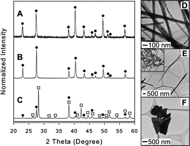
| Fig. 5 XRD patterns and TEM images for Bi-Te materials synthesized using OAM (A and D), OAC/OAM (B and E), and DT (C and F). Filled circles (●) and filled squares (■) indicate peaks assigned for hexagonal-phase Te (JCPDS card no. 036-1452) and for rhombohedral Bi2Te3 (JCPDS card no. 015-0863), respectively. For detail see ESI,† Table S12–S14. | ||
TEM and XRD results for bimetallic NPs synthesized using DT capping species are given in Fig. 5C and F. From the TEM images (Fig. 5F) captured for this sample, the NPs appear to be highly aggregated and have a disc-like morphology. The NPs are not uniform in size, but seem to be very thin as several particles can be observed that overlap each other. Some additional TEM images (ESI,† Fig. S9) collected for the resulting NPs show the varying image contrast caused by the different alignment of NDs to the electron beam where very light, roughly spherical NPs correspond to the top-down alignment and very dark rod like NPs offer a side view of the discs. The NDs have a diameter of about ∼30–50 nm and thickness of about ∼5–10 nm. The broad peaks in the XRD pattern (Fig. 5C) collected for these NPs may arise as a result of the nanoscale size and thin platelet morphology. Analysis of the composition based on assigning XRD peaks shows the presence of the Bi2Te3 phase which is consistent with the fact that both Bi and Te particles were formed in the monometallic approach using DT.
The higher standard reduction potential of Te(IV) likely leads to an initial reduction and nucleation of Te followed by the reduction of Bi complex to form Bi2Te3. The Te particle surface in this case catalyzed the decomposition of the Bi complex followed by the alternate adsorption/reduction reaction of Bi and Te, resulting in the Bi2Te3 phase and ND morphology instead of Bi elongated plates as found for Bi synthesized with DT (Fig. 1E). The formation of Bi2Te3 NDs capped with DT arises primarily as a result of the catalytic effect of Te at the particle surface in the decomposition of the Bi-DT complex which introduces an intriguing pathway to modify the final NP morphology and composition.
 | ||
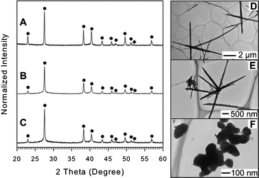
| Fig. 6 XRD patterns and TEM images for Sb-Te materials synthesized using OAM (A and D), OAC/OAM (B and E), and DT (C and F). The peak identities were labelled by the symbol filled circle (●) for Te (JCPDS card no. 036-1452) and open square (□) for Sb2Te3 (JCPDS card no. 015-0874). The inset of Fig. 6E represents a zoomed out view of synthesized NWs. For details see ESI,† Table S15–S17. | ||
Using DT as a capping system, on the other hand, leads to the formation of large platelet-like particles (Fig. 6F) composed of Sb2Te3 with a minor amount of elemental Te as indexed in the XRD pattern (Fig. 6C). The formation of two segregated phases including Sb2Te3 and Te indicates that the existence of Te NPs catalyzed the decomposition and reduction of the Sb-DT complex, which failed to be reduced in the Sb monometallic synthesis with DT (see Table 1).
Summary of the mono- and bi-metallic synthesis studies
From the study of mono- and bi-metallic syntheses, we can elucidate the role that each individual capping ligand plays, as well as the influence of the metallic interaction in the formation of the NPs. The formation of NPs is summarized for two general types of capping systems: one is DT and the other is OAM and OAC/OAM. For the first case, DT creates a relatively strong complex with the three elemental precursors, especially with Sb which could not be reduced in the monometallic synthesis. The resulting small Te nanoplates and long Bi particles without oxides and other compounds in single precursor approach show the good capping ability of DT. Furthermore, the results of the bimetallic system capped with DT highlighted the important catalytic effect of Te for Bi2Te3 and Sb2Te3 formation. We also found that NPs composed of Bi and Sb failed to be formed in DT due to the stability of Sb-DT complex along with no catalytic effect of Bi particles. Therefore, the strong bimetallic interaction of Te with Bi and/or Sb-DT complexes and the lack of Bi-Sb alloy formation explain the existence of two segregated phases obtained when using DT with all three elemental precursor synthesis.37 On the other hand, OAM or OAC/OAM, in the interaction with single precursor, directs the growth of monoelemental Sb and Te NWs as well as the BiOCl formation with a minor phase of Bi. In these capping systems, if Te does not act as catalyst for Bi or Sb complex reduction, then only monometallic Te NWs grow in the bimetallic systems. However, Bi and Sb can be incorporated into a Bi-Sb alloy NP as a result of the formation and catalytic effect of Sb on the Bi complex. Therefore, in OAM or OAC/OAM capping systems, there is a possibility of forming a (Bi,Sb)2Te3 ternary solid solution when all three elemental precursors are combined together. The general understanding of the NP formation mechanism encourages a study of the synthesis of trimetallic NPs using these capping species, towards (Bi,Sb)2Te3 ternary solid solution NPs.Study of trimetallic synthesis approach
In light of the key results obtained from the formation mechanism investigation for monometallic and bimetallic syntheses, we synthesized trimetallic NPs with the OAM capping ligand system. In this section, the OAM capping system was focused on because of the failure to synthesize a Bi-Sb alloy using the DT capping system in the bimetallic synthesis, while only Bi-Te and Sb-Te alloys could be obtained using DT. Based on these results, it is likely that Te/Bi2Te3/Sb2Te3 segregated NPs would be dominantly synthesized if DT was used in a Bi-Sb-Te trimetallic synthesis. In fact, a similar result was previously reported in which phase-segregated NDs were obtained.37 Therefore, the formation mechanism in this case is relatively simple, i.e., Te NP formation followed by Bi and Sb individual incorporation into the Te NPs due to the catalytic effect of Te without Bi-Sb interaction. Accordingly, it seems quite difficult to synthesize nanostructured (Bi,Sb)2Te3 solid solution using DT as a capping system. On the contrary, in the case of Bi-Sb bimetallic synthesis using the OAM capping system, we successfully synthesized Bi70Sb30 alloy nanoplates, while Bi-Te and Sb-Te alloys could not be obtained using OAM. It is worthwhile to investigate whether a Bi-Sb-Te cross interaction takes place. The main results and discussion of this section, therefore, will detail only trimetallic NWs synthesized with OAM capping species which give more insight into the growth mechanism of Bi-Sb-Te NPs and how to control the resulting shape, composition and structure.Using OAM as a capping ligand led to the formation of very long and high aspect ratio NWs. Fig. 7 shows the TEM images of NWs synthesized using 0.17 mL OAM (corresponding to 1![[thin space (1/6-em)]](https://www.rsc.org/images/entities/char_2009.gif) :1 molar ratio of elemental precursors to OAM). The length of the NWs is several microns with a diameter ranging from 50 to 100 nm, which gives a very high aspect ratio (∼50–100). On the surface of the NWs, there are some small NPs and the non-homogeneous local areas (reflected by different contrast) observed in the TEM images for each NW may indicate a heterogeneous composition. In addition, if one takes a close look at Fig. 7C, the center of a NW is lighter than the periphery suggesting the composition distribution in a radial direction (i.e. Bi-rich at the periphery) or the tube-like structure caused by nanoscale Kirkendall effect31 which refers to a nonreciprocal mutual diffusion through an interface of two metals. HRTEM images of a single NW is shown in Fig. S10 (ESI†) illustrating the high crystallinity of particles. The composition and crystal structure of the NWs were analyzed using ICP-MS and XRD.
:1 molar ratio of elemental precursors to OAM). The length of the NWs is several microns with a diameter ranging from 50 to 100 nm, which gives a very high aspect ratio (∼50–100). On the surface of the NWs, there are some small NPs and the non-homogeneous local areas (reflected by different contrast) observed in the TEM images for each NW may indicate a heterogeneous composition. In addition, if one takes a close look at Fig. 7C, the center of a NW is lighter than the periphery suggesting the composition distribution in a radial direction (i.e. Bi-rich at the periphery) or the tube-like structure caused by nanoscale Kirkendall effect31 which refers to a nonreciprocal mutual diffusion through an interface of two metals. HRTEM images of a single NW is shown in Fig. S10 (ESI†) illustrating the high crystallinity of particles. The composition and crystal structure of the NWs were analyzed using ICP-MS and XRD.
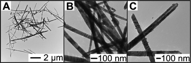 | ||
| Fig. 7
TEM images of trimetallic NWs synthesized using OAM as capping species with 1:1 molar ratio of precursors and OAM. Image (A) shows the zoomed out view of the synthesized NWs, (B) shows a magnified view of the NWs which have a narrow diameter and are smooth, and (C) shows NWs with some smaller NPs at the surface and the tip of NWs. | ||
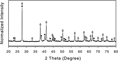
Fig. 8 shows the XRD patterns for NWs capped with OAM. XRD peaks can be indexed for several segregated phases including Te (hexagonal structure), Bi2Te3, and (Bi,Sb)2Te3 (rhombohedral structure) due to their similar crystal structures and overlapping peaks. The reference reflection of bulk (Bi0.5Sb0.5)2Te3 was used to assign the peak position of (Bi,Sb)2Te3 phase. Note that Sb2Te3, Sb or Sb oxide phases could not be found in the XRD pattern. To assign the phases definitively, the elemental assessment for NWs using ICP-MS analysis was conducted with the results of Bi15Sb26Te59, which is in general consistent with each other in the co-existence of all three metal components. Note that the accurate elemental assessment of Bi-Sb-Te ternary material is difficult using EDS because Sb and Te peaks overlap each other significantly. We conclude that dominant phases of the NWs synthesized using OAM capping system are (Bi,Sb)2Te3 (rhombohedral) and elemental Te (hexagonal) by considering the following facts: (1) the NWs have no Sb2Te3, Sb or Sb oxide phases, (2) the NWs contain a significant amount of Sb, and (3) the presence of the characteristic peaks of Te at 2θ = 22.98, 38.21, 40.38, 43.28, 49.55, 51.16, and 51.92 degrees and of (Bi,Sb)2Te3 at 2θ = 70.06°. Note that we do not rule out the existence of the Bi2Te3 phase because other peaks of the (Bi,Sb)2Te3 phase significantly overlap with the Bi2Te3 phase. For details see ESI,† Table S18.
 | ||
| Fig. 8
XRD patterns of trimetallic NWs synthesized using OAM as capping species with 1:1 molar ratio of precursors and OAM. The peak identities are labelled by the symbol filled circle (●) for Te (JCPDS card no. 036-1452), and open diamond (◊) for (Bi0.5Sb0.5)2Te3 (JCPDS card no. 01-072-1835). | ||
Summary of the nanoparticle formation mechanism
To consistently explain all the results in the systematic studies about the effect of capping ligands and metal complex interaction on NP morphology and composition, we propose two separate formation mechanisms for BiSbTe containing NPs with two kinds of capping systems: OAM and DT based on the metal–ligand complex formation, decomposition and interaction. In general, due to the high reduction potential, the Te complex was first reduced, undergoing nucleation. However, the growth of Te NPs and the incorporation of other metals strongly depend on the capping ligands (formation of complex with the metal precursors) and the metal–ligand cross-interaction.In the case for DT, a stable complex with Sb can be formed, with a less stable complex for Bi or Te. As a result, the Sb-DT complex itself could not be reduced under the synthetic conditions, but Bi and Te can be reduced and form elongated plates or nanoplates respectively. Bi was not found to catalyze the reduction of the Sb-DT complex, as indicated in the bimetallic approach which led to the formation of only monometallic Bi plates. On the other hand, Te NDs could act as a catalyst for Bi or Sb complex reduction, resulting in the formation of Bi2Te3 and Sb2Te3 materials. The existence of these two phases in trimetallic NPs synthesized using DT therefore can be explained based on the catalytic effect of Te and reaction of Te with the other metal complexes.
When OAM is used as a capping system, Te does not exhibit catalytic properties in the reduction of the other metal complexes. Moreover, the formation of Te containing NWs for all synthesis approaches with the presence of Te precursor and OAM indicated that the growth of Te NWs capped with OAM is preferential and the incorporation of other metals into the NWs is not feasible when using OAM. In this capping system, Sb was found to play a dual role in catalyzing the decomposition of the Bi complex, which prevented the formation of BiOCl. It is very important that a Bi-Sb alloy can be formed under similar synthetic conditions with OAM. The formation of these materials illustrates the possibility to form an alloy of BiSbTe when all three metal precursors are used in the synthesis. Therefore, the reduction and growth of Te NWs and Bi-Sb NPs can occur separately in the trimetallic synthesis, and the formation of the final NWs containing (Bi,Sb)2Te3 ternary solid solution may be caused by the oriented attachment42 of Te NWs and Bi-Sb NPs which was not observed in the case of using DT as capping ligand. The formation mechanism in these two cases is illustrated in Fig. 9.
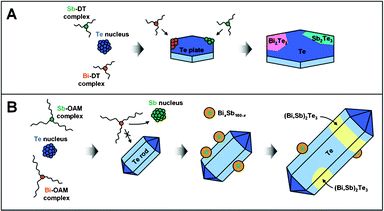 | ||
| Fig. 9 Schematic illustration of formation mechanisms for (A) Te/Bi2Te3/Sb2Te3 phase-segregated NDs synthesized using DT as a capping system and for (B) Te/(Bi,Sb)2Te3 NWs synthesized using OAM as a capping system. | ||
Conclusions
In conclusion, we have partially addressed the complexity in the growth mechanism of trimetallic nanoparticles based on the synthesis and investigation of monometallic and bimetallic systems using various capping ligands. The use of different capping ligands in the complex formation and metallic interaction result in two different pathways in the formation of trimetallic NPs. Our study illustrates the formation of Bi2Te3 and Sb2Te3 based NPs due to the Te catalytic effect on the decomposition of the Sb and Bi precursor complexes. A bimetallic interaction was also observed in the case of using DT capping species. The formation of BiSb alloy in the OAM based capping system is important for the formation of a trimetallic alloy, which is observed in the triple elemental synthetic approach. The understanding of the NP formation mechanism arising from this expansive study gives a fundamental understanding of how to further control the composition, structure and characteristics of trimetallic NPs towards TE materials with enhanced and promising properties. Part of the ongoing work includes further delineation of the synthetic parameters, including precursor concentrations as well as characterization of the TE properties of these materials.Acknowledgements
This work was supported by the Grant-in-Aid for Scientific Research (C). Nguyen T. Mai would like to thank the Vietnamese Government for a 322 scholarship. We thank Drs. M. Koyano and K. Suekuni from JAIST for valuable advice and discussion.References
- G. J. Snyder and E. S. Toberer, Nat. Mater., 2008, 7, 105 CrossRef CAS.
- Thermoelectrics Handbook: Macro to Nano, D. M. Rowe, Ed.; CRC Press: Boca Raton, FL, 2006 Search PubMed.
- M. V. Kovalenko, B. Spokoyny, J.-S. Lee, M. Scheele, A. Weber, S. Perera, D. Landry and D. V. Talapin, J. Am. Chem. Soc., 2010, 132, 6686 CrossRef CAS.
- Y.-M. Lin and M. S. Dresselhaus, Phys. Rev. B: Condens. Matter, 2003, 68, 075304 CrossRef.
- B. Yoo, F. Xia, K. N. Bozhilov, J. Herman, M. A. Ryan and N. V. Myung, Adv. Mater., 2007, 19, 296 CrossRef CAS.
- A. E. Saunders, A. Ghezelbash, D.-M. Smilgies, M. B. Sigman and B. A. Korgel, Nano Lett., 2006, 6, 2959 CrossRef CAS.
- R. Venkatasubramanian, E. Siivola, T. Colpitts and B. O'Quinn, Nature, 2001, 413, 597 CrossRef CAS.
- Y. Zhao, J. S. Dyck, B. M. Hernandez and C. Burda, J. Phys. Chem. C, 2010, 114, 11607 CAS.
- Y. Q. Cao, T. J. Zhu, X. B. Zhao, X. B. Zhang and J. P. Thu, Appl. Phys. A: Mater. Sci. Process., 2008, 92, 321 CrossRef CAS.
- S. H. Li, M. S. Toprak, H. M. A. Soliman, J. Zhou, M. Muhammed, D. Platzek and E. Muller, Chem. Mater., 2006, 18, 3627 CrossRef CAS.
- S. H. Li, H. M. A. Soliman, J. Zhou, M. S. Toprak, M. Muhammed, D. Platzek, P. Ziolkowski and E. Muller, Chem. Mater., 2008, 20, 4403 CrossRef CAS.
- F. Xiao, C. Hangarter, B. Yoo, Y. Rheem, K.-H. Lee and N. V. Myung, Electrochim. Acta, 2008, 53, 8103 CrossRef CAS.
- H. Ebe, M. Ueda and T. Ohtsuka, Electrochim. Acta, 2007, 53, 100 CrossRef CAS.
- A. Bailini, F. Donati, M. Zamboni, V. Russo, M. Passoni, C. S. Casari, A. L. Bassi and C. E. Bottani, Appl. Surf. Sci., 2007, 254, 1249 CrossRef CAS.
- C. N. Liao, K. M. Liou and H. S. Chu, Appl. Phys. Lett., 2008, 93, 042103 CrossRef.
- S. S. Kim, S. Yamamoto and T. Aizawa, J. Alloys Compd., 2004, 375, 107 CrossRef CAS.
- X. A. Fan, J. Y. Yang, R. G. Chen, W. Zhu and S. Q. Bao, Mater. Sci. Eng., A, 2006, 438–440, 190 CrossRef.
- J. L. Cui, H. F. Xue, W. J. Xiu, L. Jiang and P. Z. Ying, J. Solid State Chem., 2006, 179, 3751 CrossRef CAS.
- T.-S. Kim and B.-S. Chun, J. Alloys Compd., 2007, 437, 225 CrossRef CAS.
- R. J. Mehta, C. Karthik, W. Jiang, B. Singh, Y. Shi, R. W. Siegel, T. Borca-Tasciuc and G. Ramanath, Nano Lett., 2010, 10, 4417 CrossRef CAS.
- R. J. Mehta, C. Karthik, B. Singh, R. Teki, T. Borca-Tasciuc and G. Ramanath, ACS Nano, 2010, 4, 5055 CrossRef CAS.
- X. F. Qiu, C. Burda, R. L. Fu, L. Pu, H. Y. Chen and J. J. Zhu, J. Am. Chem. Soc., 2004, 126, 16276 CrossRef CAS.
- W. Wang, J. Goebl, L. He, S. Aloni, Y. Hu, L. Zhen and Y. Yin, J. Am. Chem. Soc., 2010, 132, 17316 CrossRef CAS.
- Y. Xu, Z. Ren, G. Cao, W. Ren, K. Deng and Y. Zhong, Mater. Lett., 2008, 62, 4525 CrossRef CAS.
- Y. Deng, C.-W. Nan, G.-D. Wei, L. Guo and Y. Lin, Chem. Phys. Lett., 2003, 374, 410 CrossRef CAS.
- W. Lu, Y. Ding, Y. Chen, Z. L. Wang and J. Fang, J. Am. Chem. Soc., 2005, 127, 10112 CrossRef CAS.
- A. Purkayastha, S. Kim, D. D. Gandhi, P. G. Ganesan, T. Borca-Tasciuc and G. Ramanath, Adv. Mater., 2006, 18, 2958 CrossRef CAS.
- A. Scheele, N. Oeschler, K. Meier, A. Kornowski, C. Klinke and H. Weller, Adv. Funct. Mater., 2009, 19, 3476 CrossRef.
- J.-J. Kim, S.-H. Kim, S.-W. Suh, D.-U. Choe, B.-K. Park, J. R. Lee and Y.-S. Lee, J. Cryst. Growth, 2010, 312, 3410 CrossRef CAS.
- A. Purkayastha, Q. Y. Yan, M. S. Raghuveer, D. D. Gandhi, H. F. Li, Z. W. Liu, R. V. Ramanujan, T. Borca-Tasciuc and G. Ramanath, Adv. Mater., 2008, 20, 2679 CrossRef CAS.
- G. Zhang, Q. Yu, Z. Yao and X. Li, Chem. Commun., 2009, 2317 Search PubMed.
- J. Yang, T. Aizawa, A. Yamamoto and T. Ohta, J. Alloys Compd., 2000, 309, 225 CrossRef CAS.
- J. Jiang, L. Chen, S. Bai, Q. Yao and Q. Wang, J. Cryst. Growth, 2005, 277, 258 CrossRef CAS.
- Y. Xu, Z. Ren, W. Ren, K. Deng and Y. Zhong, Mater. Lett., 2008, 62, 763 CrossRef CAS.
- Y. Zhao and C. Burda, ACS Appl. Mater. Interfaces, 2009, 1, 1259 CAS.
- M. Scheele, N. Oeschler, I. Veremchuk, K.-G. Reinberg, A.-M. Kreuziger, A. Komowski, J. Broekaert, C. Klinke and H. Weller, ACS Nano, 2010, 4, 4283 CrossRef CAS.
- D. Mott, N. T. Mai, N. T. B. Thuy, Y. Maeda, T. P. T. Linh, M. Koyano and S. Maenosono, Phys. Status Solidi A, 2011, 208, 52 CrossRef CAS.
- Z. Liu, Z. Hu, J. Liang, S. Li, Y. Yang, S. Peng and Y. Quian, Langmuir, 2004, 20, 214 CrossRef CAS.
- S. Saita and S. Maenosono, Chem. Mater., 2005, 17, 6624 CrossRef CAS.
- D. D. Fanfair and B. A. Korgel, Cryst. Growth Des., 2008, 89, 3246 Search PubMed.
- J.-L. Mi, N. Lock, T. Sun, M. Christensen, M. Søndergaard, P. Hald, H. H. Hng, J. Ma and B. B. Iversen, ACS Nano, 2010, 4, 2523 CrossRef CAS.
- Y. Deng, C. W. Nan and L. Guo, Chem. Phys. Lett., 2004, 383, 572 CrossRef CAS.
- R. Malakooti, L. Cademartiri, Y. Akcakir, S. Petrov, A. Migliori and G. A. Ozin, Adv. Mater., 2006, 18, 2189 CrossRef CAS.
- A. M. Ibrahim and D. A. Thompson, Mater. Chem. Phys., 1985, 12, 29 CrossRef CAS.
- W. F. Ehret and M. B. Abramson, J. Am. Chem. Soc., 1934, 56, 385 CrossRef CAS.
- Y. Li and J. Liu, Chem. Mater., 2001, 13, 1008 CrossRef CAS.
- K. A. Abboud, R. C. Palenik and R. M. Wood, Inorg. Chim. Acta, 2007, 360, 3642 CrossRef CAS.
Footnote |
| † Electronic supplementary information (ESI) available: SEM and HRTEM images of Sb and Te NWs, XRD peak assignments for all samples, photographs of metal–ligand complexes, FTICR-MS spectrum and TGA data of Sb-DT complex, HRTEM image of BiSb NPs, relationship between lattice spacing and composition of BiSb alloy, comparison of XRD peak position collected for NPs synthesized using BiCl3 and BiCl3/SbCl3 with DT as capping ligands, bimetallic synthesis of Bi-Te halide precursors and DT, HRTEM images of a single Bi-Sb-Te NW, and results for trimetallic approach using oleic acid as capping system. See DOI: 10.1039/c1ra00069a |
| This journal is © The Royal Society of Chemistry 2011 |