Hierarchical Bi7O9I3 micro/nano-architecture: facile synthesis, growth mechanism, and high visible light photocatalytic performance†
Xin
Xiao
ab and
Wei-De
Zhang
*a
aSchool of Chemistry and Chemical Engineering, South China University of Technology, Guangzhou, 510640, PR China. E-mail: zhangwd@scut.edu.cn (W. D. Zhang); Fax: +86 20 8711 4099; Tel: +86 20 8711 4099
bSchool of Chemistry and Environment, South China Normal University, Guangzhou, 510006, PR China
First published on 15th September 2011
Abstract
Bi7O9I3, a fresh member of the bismuth oxyhalide family, with hierarchical micro/nano-architecture is successfully synthesized by a one-step, template and surfactant-free solution method. The as-prepared product was characterized by various techniques. X-ray diffraction, X-ray photoelectron spectroscopy and thermogravimetric analysis confirm that the composition of the as-fabricated sample is Bi7O9I3. Scanning and transmission electron microscopy observations reveal that the as-synthesized sample exhibits a microsized plate-like structure with dense nanosheets standing on their surfaces. The time-dependent morphology of the Bi7O9I3 sample was investigated, and a possible formation mechanism of the hierarchical structure is proposed. More importantly, the Bi7O9I3 exhibits an excellent photocatalytic activity in the degradation of phenol under visible light irradiation. The high catalytic performance of the Bi7O9I3 hierarchical structure comes from its electronic band structure, high surface area and high surface-to-volume ratio. In addition, the Bi7O9I3 hierarchical architecture is stable during the reaction and can be used repeatedly. The present work not only gives insight into understanding the hierarchical growth behaviour of complex bismuth oxide iodide structures in a solution-phase synthetic system, but also provides a new way to improve the photocatalytic performance by designing desirable structures and morphologies.
1. Introduction
In the past decade, a large number of investigations have focused on semiconductor photocatalysis due to its potential applications for solar energy conversion and environmental purification.1–3 Among the diverse photocatalytic materials, nano-scaled TiO2 has received the most attention because of its strong oxidizing power, non-toxicity, low cost, biological and chemical inertness, and long-term stability against photo and chemical corrosion.4–6 However, TiO2 is effective only under ultraviolet irradiation (λ < 380 nm) because of its large band gap, which limits its practical application under solar light or indoor usage.7–9 In view of the efficient utilization of visible light, which accounts for a large proportion of the solar spectrum and artificial light sources, current studies on photocatalysis are exploring new photocatalysts driven by visible light.It is well known that the intrinsic properties of materials are determined not only by their chemical composition but also by their shape, size and structure. Hierarchically structured materials, which possess dual or multiple morphologies and structures, are greatly valuable for high performance and further applications.10–12 Especially, for a specific photocatalyst, hierarchical architectures fabricated from nano-scale building blocks hold many advantages, such as a high surface-to-volume ratio, anti-aggregation ability, abundant transport paths for small organic molecules, and good recyclability.13–15 Therefore, photocatalysts with hierarchical architectures are expected to exhibit enhanced photocatalytic performance. However, the direct fabrication of hierarchical micro/nano-structures based on the assembly of nanosized building blocks into three-dimensional (3D) superstructures remains a challenge.
Recently, as novel ternary oxide semiconductors, bismuth oxyhalides (BiOX, X = F,16Cl,17–19Br,20–22 and I23–26) have drawn much attention for their potential application in photocatalysis due to their uniquely layered structures with the internal static electric field perpendicular to each layer, which can induce the effective separation of photo-generated electron–hole pairs, and therefore achieve a high photocatalytic performance. Among them, BiOI has the smallest band gap (∼1.8 eV) and strong absorption in the visible-light region (the absorption edge is ∼680 nm), thus shows excellent photocatalytic performance under sunlight irradiation.23,25,27 Except for BiOI, other bismuth oxyiodides, including Bi4O5I2,28,29Bi7O9I3,29,30α-Bi5O7I31,32 and β-Bi5O7I,33 are also known to researchers. Since the valence band in BiOX is mainly composed of Bi 6s, O 2p and X 5p orbits, while the conduction band is based on Bi 6s and Bi 6p orbits,34,35 the bandgap energy of bismuth oxyiodides may gradually increase by substitution of I with O in their structures, resulting in a lower bandgap than that of Bi2O336,37 (∼2.83 eV, the absorption edge is ∼440 nm). Therefore, all these kinds of bismuth oxyiodides are expected to demonstrate visible light photocatalytic activity. However, only a few studies have been reported for the photocatalysis of bismuth oxyiodides besides BiOI. Very recently, Sun’s group has shown that Bi5O7I prepared by a hydrothermal method exhibited efficient photocatalytic activity in the decomposition of tetraethylated rhodamine and acetaldehyde under visible light irradiation.38Bi5O7I was also obtained by thermal decomposition of BiOI at 450–650 °C.39 By controlling the precipitation pH, BiOI, Bi4O5I2, Bi7O9I3 plates and Bi5O7I rods were prepared via a precipitation–filtration process followed by hydrothermal treatment.40
In this article, a novel hierarchical Bi7O9I3 micro/nano-architecture was synthesized by a one-step, template and surfactant-free solution approach under normal atmospheric pressure. It exhibits a microsized plate-like structure of many nanosheets with a thickness of ca. 10 nm on the surface of the plates. Such a hierarchical structure shows strong structure-induced enhancement of photocatalytic performance and exhibits significantly improved photocatalytic property and durability for photodegradation of phenol under visible light irradiation. The possible structure and formation mechanism for the architecture are carefully characterized and discussed. This work not only gives insight into understanding the hierarchical growth behaviour of complex bismuth oxyiodides micro/nano-architectures in a solution-phase synthetic system, but also provides an efficient route to enhance the photocatalytic performance of bismuth oxyhalide catalysts.
2. Materials and methods
Bismuth nitrate pentahydrate (Bi(NO3)3·5H2O) and potassium iodide (KI) were bought from Tianjin Kermel Chemical Reagent Co. Ltd. (Tianjin, China) and were used as the Bi and I sources, respectively. Other chemicals were purchased from local chemical agents and were of analytical grade. All the above chemicals were used without further purification and distilled water was used in all experiments. For the preparation of hierarchical Bi7O9I3 microplates, 0.728 g of Bi(NO3)3·5H2O was dissolved completely in 20 ml ethylene glycol (EG) and 0.249 g KI was dissolved in 10 ml EG by stirring at room temperature, respectively. Then, 30 ml EG was placed in a 150 ml three necked round-bottom flask and pre-heated to 160 °C using an oil bath with continuous stirring and a refluxing system carried out in a hood. After that, the above potassium iodide solution was then added into the heated EG and stirred for 10 min. Finally, the bismuth nitrate solution was added rapidly to the previous mixture and stirred continuously for another 3 h at 160 °C. The precipitates were air cooled to room temperature and collected by centrifugation, washed several times with distilled water as well as ethanol and dried in an oven overnight at 60 °C. For comparison, BiOI microspheres were prepared according to the literature23 using a solvothermal process and their corresponding photocatalytic performance was also examined.The morphology of the samples was investigated by scanning electron microscopy (SEM, JSM-6380-LA, JEOL, Japan) and transmission electron microscopy (TEM, Philips EM400, The Netherlands). X-Ray diffraction (XRD) analysis was performed on an X-ray diffractometer (X'Pert PRO MRD, PANalytical, the Netherlands) equipped with a Cu Kα X-ray source. The surface elemental component and the chemical state of the sample were analyzed by X-ray photoelectron spectroscopy (XPS, Axis Ultra DLD, Kratos Analytical, UK) with a monochromatized Al Kα X-ray source (hν = 1486.6 eV). The thermogravimetric analysis (TGA) was performed using a thermal analyzer (Netzsch STA 449C, Germany) with a heating rate of 10 °C min−1 and the range of temperature from 30 to 850 °C in air atmosphere. UV-vis diffuse reflection spectra (DRS) of the samples were obtained using a UV-vis spectrophotometer (UV-3010, Hitachi, Japan). The Brunauer–Emmett–Teller (BET) surface area was determined by a ST-08A measuring instrument (Beijing Analysis Instruments Technical Company, China). The photoabsorption of phenol solution was evaluated by UV-vis spectroscopy (UV-1800, Shimadzu, Japan).
The photocatalytic activities of the as-prepared samples were evaluated by degradation of phenol in aqueous solution under visible light irradiation. The reaction was performed in a photochemical reactor (XPA-VII, Nanjing Xujiang Machine- electronic Plant, China), equipped with a 1000 W Xe lamp combined with a 420 nm cut-off filter as a light source. All photocatalytic reactions were performed using the same initial conditions: 50 ml phenol solution (25 mg l−1) was mixed with 50 mg catalyst, under constant magnetic stirring. Prior to irradiation, the solution was stirred for 1 h in the dark to allow the system to reach adsorption equilibrium. Throughout the reaction, about 3 ml of the suspension was removed every 1 h. The concentration of phenol in the samples was determined by UV-vis spectroscopy (λ = 270 nm or detected over a range of 200–800 nm).
3. Results and discussion
The powder X-ray diffraction (XRD) pattern provides crystal structure and phase information of the as-synthesized sample (Fig. 1). The strong peaks indicate that the obtained product is highly crystallized. In the region of 5–90°, the diffractive pattern of the sample is quite similar to that of the hexagonal structure for BiOI (JCPDS No. 73-2062, the black lines in Fig. 1), and no characteristic peaks of bismuth oxides, basic bismuth nitrate or any other impurities were observed in the pattern. However, it is interesting to note that the positions of all the diffraction peaks of the sample shift slightly to smaller diffraction angles compared with those of standard BiOI. A more careful analysis reveals that the peaks are positioned at 2θ of 28.7, 31.5, 36.8, 45.2, 49.2 and 54.6° (the red line in Fig. 1). All diffraction peaks match exactly with those of Bi7O9I3.29,30,40 This shift of peak position in the as-prepared sample can be attributed to the extra bismuth and oxygen in the lattice, thus causing expansion26 and distortion of the standard BiOI crystal structure.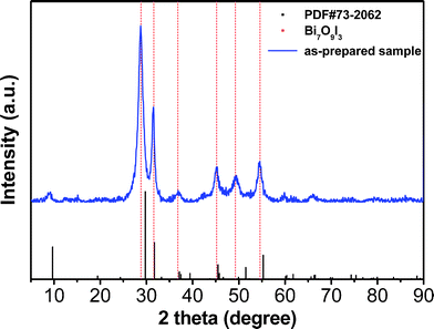 | ||
| Fig. 1 XRD pattern of the as-prepared sample. | ||
The X-ray photoelectron spectroscopy (XPS) measurements provide further information for the evaluation of the surface elemental composition and purity of the product. The binding energy obtained in the XPS analysis was corrected for specimen charging by referencing C 1s to 284.50 eV. Fig. 2A shows a typical XPS survey spectrum of the prepared sample. No peaks of other elements except C, O, Bi and I are observed in the spectrum, indicating the high purity of this product. Fig. 2B, 2C and 2D show the high-resolution XPS spectra of Bi 4f, I 3d and O 1s, respectively. The two strong peaks at the Bi region (Fig. 2B) of 158.8 and 164.2 eV are respectively assigned to Bi 4f 7/2 and Bi 4f 5/2, which are characteristics of Bi3+.18,41 The peaks with binding energies of 618.9 eV and 630.3 eV are I 3d spin-orbital doublets, I 3d 5/2 and I 3d 3/2, respectively (Fig. 2C), which indicates that the state of I in the sample is −1 valence.41,42 Similarly, the O 1s core level spectrum (Fig. 2D) can be fitted well with two peaks. The dominant peak at 529.8 eV is characteristic of a bismuth–oxygen bond in BiOX, and the other peak at 531.8 eV is mainly attributed to the chemisorbed H2O or OH− on the surface, respectively.41,43 The XPS quantitative data (see Electronic Supplementary Information, Table S1†) reveal that the atomic ratio of Bi, O, and I was 7![[thin space (1/6-em)]](https://www.rsc.org/images/entities/char_2009.gif) :
:![[thin space (1/6-em)]](https://www.rsc.org/images/entities/char_2009.gif) 9.8
9.8![[thin space (1/6-em)]](https://www.rsc.org/images/entities/char_2009.gif) :
:![[thin space (1/6-em)]](https://www.rsc.org/images/entities/char_2009.gif) 2.97 on the basis of the areas of the Bi, O, and I peaks within experimental error.
2.97 on the basis of the areas of the Bi, O, and I peaks within experimental error.
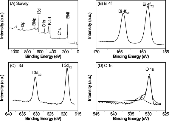 | ||
| Fig. 2 XPS spectra of the as-prepared samples: (A) survey scan, (B) Bi 4f, (C) I 3d, and (D) O 1s. | ||
TGA measurements were carried out to further investigate the variations of the prepared Bi7O9I3 sample and BiOI sample during thermal treatment. The results are shown in Fig. 3. The thermal degradation of BiOI was characterized by two mass loss steps. The first step in the temperature range approximately 350–520 °C was attributed to the transformation from BiOI to Bi5O7I, whereas the second step (in the range 600–850 °C) was ascribed to transformation from Bi5O7I to Bi2O3:39
 | (1) |
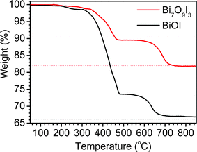 | ||
| Fig. 3 TG profiles of Bi7O9I3 and BiOI samples in air flow. | ||
The TG curve of the Bi7O9I3 sample also shows a similar tendency of weight loss. However, the total weight decreases only about 10% and another 8% in the corresponding temperature range with that of BiOI, which can be described as eqn (2):
 | (2) |
Consequently, the product can be determined as pure Bi7O9I3 based on the results of XRD, XPS and TG analysis.
Fig. 4 demonstrates the corresponding morphology of the synthesized Bi7O9I3 sample. From the SEM observation, the product consists of a large number of plate-like microsized particles and most of them have a parallelogram shape (Fig. 4A and 4B). The size of the entire hierarchical structure ranges from 20 to 40 μm. The high-magnification scanning electron microscopy images (Fig. 4C and 4D) show that the plate-like architecture seems to be built of numerous nanosheets that stand on the surface of the plate and connect with each other to form networks. It can also be observed from Fig. 4D that each plate was composed of several layers. TEM characterization further confirms the architecture of the as-prepared sample. Fig. 4E exhibits that the parallelogram-like products are sufficiently stable after ultrasonic treatment. Fragments of the sample, as shown in Fig. 4F, are nanosheets.
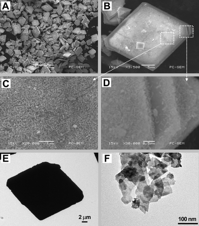 | ||
| Fig. 4 SEM and TEM images of the hierarchical Bi7O9I3 microplates at different magnifications, (A) low-magnification SEM image, (B) an individual architecture viewed from the frontal perspective, (C) high-magnification SEM image of a top-view image of (B), (D) high-magnification SEM image at the edge of (B), (E) TEM image of individual microplates, and (F) TEM image of small fragments of the sample. | ||
It is interesting to note that at the same reaction temperature (160 °C), although using the same ratio of Bi3+/I− (1![[thin space (1/6-em)]](https://www.rsc.org/images/entities/char_2009.gif) :
:![[thin space (1/6-em)]](https://www.rsc.org/images/entities/char_2009.gif) 1) and the same solvent (ethylene glycol), the composition, structure and morphology of the synthesized sample are totally different from the compared sample prepared by a solvothermal process,23 which is in 3D hierarchical BiOI nanoplate microspheres (see Electronic Supplementary Information, Fig. S1†). The results suggest the different formation mechanism for the two samples.
1) and the same solvent (ethylene glycol), the composition, structure and morphology of the synthesized sample are totally different from the compared sample prepared by a solvothermal process,23 which is in 3D hierarchical BiOI nanoplate microspheres (see Electronic Supplementary Information, Fig. S1†). The results suggest the different formation mechanism for the two samples.
In both preparation procedures, ethylene glycol acts as a high-boiling point solvent, stabilizer and coordinating agent44 to prevent the rapid hydrolysis of Bi(NO3)3 and producing HNO3:
 | (3) |
When the system is heated to the reaction temperature (above 140 °C), Bi2(OCH2CH2O)3, H2O and KI can react to form bismuth oxyiodides:
 | (4) |
Meanwhile, at high temperature, nitric acid may decompose (Reaction (5)) and act as strong oxidizing agents to oxidize I− (Reaction (6)):
 | (5) |
 | (6) |
For the solvothermal process using the autoclave as reaction vessel, reactions (5) and (6) were inhibited since the sealed condition is unfavorable for the gas generating reactions. However, in the open system with high temperature, reactions (5) and (6) easily occur. What is more, reaction (3) produces H+, therefore the pH value of the solution decreases after the reaction. On the contrary, reactions (5) and (6) consume H+, which result in a higher pH after reaction. The acidic condition is favorable for the formation of BiOI (in the solvothermal process), whereas the relatively high pH benefits the formation of other iodine-poor bismuth oxyiodides.38,40 To confirm our assumption, the pH of the system was monitored during the reaction. Before the reaction, the pH of the solution containing 0.728 g Bi(NO3)3·5H2O dissolved completely in 60 ml EG is 1.2. After its reacted for 2 min, it is 2.5, then 4.5 for 5 min, and finally reaches 5.0. In addition, some iodide ions would eliminate from the solution and I2 was produced and then sublimed away at such a high temperature in an open system (reaction (6)). We noticed that shortly after the reaction started (<5 min), the solution changed from light yellow to dark-purple and then purple gas was released violently. The gas can change filter paper (dipped in starch solution before use) from white to blue. These phenomena affirm that I2 was produced during the preparation procedure. However, the reason for the formation of single Bi7O9I3 instead of other iodine-poor bismuth oxide iodides such as Bi4O5I2 or their mixtures is not clear now and needs further investigation. It could be a result of its smallest formation enthalpy among all of the bismuth oxyiodides30 and a suitable pH value of the reaction system.
To reveal the growth process of the hierarchical Bi7O9I3 microplates, time-dependent experiments were carried out and the resulting products collected at different stages were analyzed by SEM (Fig. 5) and XRD (Electronic Supplementary Information, Fig. S2†). As shown in Fig. 5A, irregular flower-like particles composed of flakes with diameters of ca. 1 μm are obtained at an early stage (5 min). After reaction for 30 min, these flower-like structures aggregate together to form larger particles with a diameter of 2–5 μm (Fig. 5B). When the reaction time is prolonged to 1 h, these aggregates become strong and a few plate structures can be found (Fig. 5C). After 3 h of reaction, plate architectures are obtained on a large scale (Fig. 5D). A magnified SEM image shows that these plate-like architectures are also formed with numerous nanosheets standing on their surface (see the Fig. 4C). Fig. S2 in the Electronic Supplementary Information shows XRD patterns of the samples with different reaction time.† As can be seen from Fig. S2a, the product obtained is highly crystallized in a very short reaction time (5 min) with a Bi7O9I3 structure. This is due to the fact that the reaction system was pre-heated to a high temperature (160 °C). Therefore, the reaction is swift and a high degree of crystallized products can be easily obtained. As the reaction time was prolonged, the crystallinity of the products was increased and the intensity ratio of the peak at 28.7° to the peak at 31.5° steadily decreased, which implies anisotropic growth of the structure. The XRD results correspond to the morphology changes of the products.
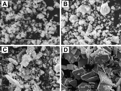 | ||
| Fig. 5 SEM images of Bi7O9I3 samples attained after reaction for (A) 5 min, (B) 30 min, (C) 1 h and (D) 3 h. | ||
On the basis of the above SEM observation and XRD analysis, the formation mechanism of Bi7O9I3 hierarchical microplates can be explained by an aggregation and dissolution–recrystallization process (i.e., Ostwald ripening) (Scheme 1). At the beginning of the reaction, Bi3+, I− ions and H2O mixed and quickly formed small crystal nuclei of Bi7O9I3 due to relatively high pH value and temperature of the system. Then these first-born crystal nuclei developed rapidly into nanosheets due to pre-heating at high temperature of the reaction system. The initially formed Bi7O9I3 nanosheets with small size tend to aggregate into large particles to reduce their surface energy, and then spontaneously generate a dissolution–recrystallization process known as Ostwald ripening.45,46 Upon prolonging the reaction time, the dissolution–recrystallization process is inclined to grow into new two-dimensional parallelogram-like structures because of the intrinsic crystal nature of Bi7O9I3. As a result, hierarchical Bi7O9I3 formed plate-like structure with numerous nanosheets standing on their surface occur.
 | ||
| Scheme 1 Formation mechanism of Bi7O9I3 hierarchical micro/nano-architecture. | ||
Optical absorption of the as-prepared Bi7O9I3 sample was measured using an UV-vis spectrometer. As shown in Fig. 6, the Bi7O9I3 sample shows strong photoabsorption from UV to visible light, and the wavelength of the absorption edge is 606 nm. The band gap of the sample can be evaluated from the following equation:23
 | (7) |
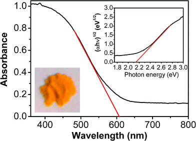 | ||
| Fig. 6 UV-vis diffuse reflectance spectrum of the Bi7O9I3 sample. The inset shows the plots of (αhν)1/2vs.photon energy (hν). | ||
In order to evaluate the photocatalytic activities of the synthesized samples, degradation of a typical organic contaminant phenol in aqueous solution under visible light irradiation was chosen as the photoreaction probe. Fig. 7A displays the change of the phenol concentration versus the reaction time over the hierarchical Bi7O9I3 microplates, BiOI microspheres (compared sample) and blank (without catalyst), which clearly indicates that with identical visible light exposure, phenol could hardly be degraded without any photocatalyst, while the Bi7O9I3 sample shows a much higher activity than that of the BiOI microspheres. After irradiating for 4 h, the phenol removal rate over the Bi7O9I3 reaches 94%, while only a 45% removal rate over the BiOI microspheres is observed during the same time period. Fig. 7B shows the absorption spectra of the phenol solutions under visible light irradiation for various durations in the photocatalytic degradation process over the Bi7O9I3 sample. The absorption peaks at 270 nm corresponding to phenol diminished gradually as the exposure time increases and almost completely disappears after 4 h. No new absorption bands appear in either the visible or the UV region, which indicates the efficient photocatalytic degradation of phenol by this system.
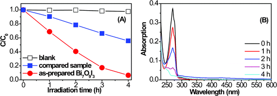 | ||
| Fig. 7 (A) Photocatalytic degradation of phenol over Bi7O9I3 hierarchical microplates, BiOI microspheres and without catalyst under visible light irradiation. (B) UV-vis absorption spectra of phenol over the Bi7O9I3 sample during the photocatalytic process. | ||
Several reasons are presumed to account for the high photocatalytic activity of the hierarchical Bi7O9I3 microplates prepared in this study. Firstly, the band gap of the as-synthesized Bi7O9I3 (2.14 eV) is wider than that of BiOI (∼1.8 eV). Fig. S3 (Electronic Supplementary Information†) shows the band structures of BiOX (X = Cl, Br, I) and Bi2O3. According to the early analysis of band gap and crystal structure of bismuth oxyiodides, it can be predicted that the top of the valence band of Bi7O9I3 is more positive than that of BiOI, which means it has a strong oxidizing power.51–53 As for the photocatalytic performance of the BiOXs with different halogen ratios of Cl−/I− and Br−/I−, 54–56 it is found that substitution of I− with a small quantity of Cl− or Br− will result in the obtained catalysts having larger band gaps, higher valence band edge potential (EVB) and higher photocatalytic performance, which is in good alignment with the results of this study. Secondly, it is generally accepted that the catalytic process is mainly related to the adsorption of reactant molecules on the surface of the catalyst.14 The surface area of the hierarchical Bi7O9I3 microplates fabricated from nanosheets was calculated using N2 adsorption to be 28.3 m2 g−1, which is larger than that of other reported BiOI hierarchical structures.23,25 As a result, more coordination sites on the unsaturated surface are exposed to the solution and the hierarchical microplates allow more efficient transport for the reactant molecules to access the active sites, hence enhancing the photocatalytic efficiency.22 What is more, the high catalytic activity is related to the high surface-to-volume ratios and the hierarchical micro/nano structure. Such 3D interconnected channels formed by Bi7O9I3 nanosheets provide efficient transport paths for reactants and products in photocatalytic reactions.57,58 The last two reasons may account for the poor photocatalytic activity of the Bi7O9I3 sample reported in the literature,40 in which the samples obtained have a very low surface area and do not have a pore structure.
The larger size of the Bi7O9I3 micro/nano-architecture leads to the easier separation and recycling of such catalysts by means of a simple natural settlement step within a few minutes (as shown in Fig. S4, Electronic Supplementary Information†). To investigate the recyclability of the Bi7O9I3 photocatalyst, sample powders after photocatalytic reactions were collected by natural settling and reused for photocatalytic reaction 4 times under the same conditions. As shown in Fig. 8A, the Bi7O9I3 sample displays an excellent stability and maintains a similar level of photocatalytic performance during four reaction cycles. Additionally, SEM observation on the Bi7O9I3 sample after the photocatalytic reaction, as indicated in Fig. 8B, reveals that their structure and morphology remain intact. These results indicate that the Bi7O9I3 microplates prepared by this facile method are stable for the photocatalysis of pollutants, which is important for practical application.
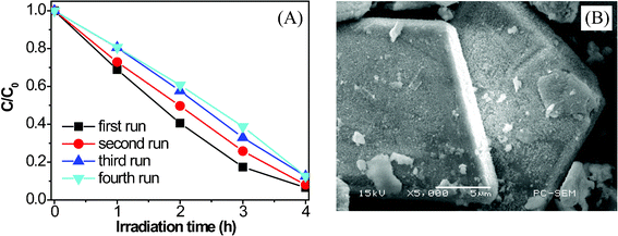 | ||
| Fig. 8 (A) Reuse of the hierarchical Bi7O9I3 microplates and (B) SEM image of the Bi7O9I3 microplates after the fourth run of photocatalytic reaction. | ||
4. Conclusion
In summary, a novel Bi7O9I3 hierarchical micro/nano-architecture with dense nanosheet-built networks standing on plate-like microcrystals has been synthesized by a facile solution procedure in the absence of any template or surfactant under normal atmospheric pressure. XRD analysis and SEM observation of the products illustrate that the formation of the hierarchical nanostructured Bi7O9I3 microplates went through an aggregation, Ostwald ripening and anisotropic growth process. The special structural feature of the micro/nano-architectured Bi7O9I3, i.e., stronger oxidizing power, high surface area and high surface-to-volume ratio, leads to high photocatalytic activity, as is demonstrated in the decomposition of phenol under visible light irradiation. The Bi7O9I3 microplates could be promising candidates for photocatalysis applications because of the facileness in separation, recycling, and large scale production. The present work not only opens new strategies for the controllable synthesis of the hierarchical micro/nano-structures based on 2D nanoscale building blocks, but also provides a step forward in the design of photocatalysts with desirable structure and morphology, and with enhanced photocatalytic activities as well.Acknowledgements
The authors thank the National Natural Science Foundation of China (No. 21043005) for financial support.References
- A. Kudo and Y. Miseki, Chem. Soc. Rev., 2009, 38, 253 RSC.
- K. Pirkanniemi and M. Sillanpaa, Chemosphere, 2002, 48, 1047 CrossRef.
- M. R. Hoffmann, S. T. Martin, W. Y. Choi and D. W. Bahnemann, Chem. Rev., 1995, 95, 69 CrossRef CAS.
- O. Carp, C. L. Huisman and A. Reller, Prog. Solid State Chem., 2004, 32, 33 CrossRef CAS.
- K. Hashimoto, H. Irie and A. Fujishima, Jpn. J. Appl. Phys., 2005, 44, 8269 CrossRef CAS.
- X. Chen and S. S. Mao, Chem. Rev., 2007, 107, 2891 CrossRef CAS.
- M. Anpo and M. Takeuchi, J. Catal., 2003, 216, 505 CrossRef CAS.
- D. Chatterjee and S. Dasgupta, J. Photochem. Photobiol., C, 2005, 6, 186 CrossRef CAS.
- Z. G. Zou, J. H. Ye, K. Sayama and H. Arakawa, Nature, 2001, 414, 625 CrossRef CAS.
- G. J. D. A. Soler-Illia, C. Sanchez, B. Lebeau and J. Patarin, Chem. Rev., 2002, 102, 4093 CrossRef.
- Y. Li, M. Zheng, L. Ma, M. Zhong and W. Shen, Inorg. Chem., 2008, 47, 3140 CrossRef CAS.
- W. Wang, L. Zhen, C. Xu, L. Yang and W. Shao, Cryst. Growth Des., 2008, 8, 1734 CrossRef CAS.
- X. Song and L. Gao, J. Phys. Chem. C, 2008, 112, 15299 CrossRef CAS.
- D. Ma, S. Huang, W. Chen, S. Hu, F. Shi and K. Fan, J. Phys. Chem. C, 2009, 113, 4369 CrossRef CAS.
- Q. Wu, X. Chen, P. Zhang, Y. Han, X. Chen, Y. Yan and S. Li, Cryst. Growth Des., 2008, 8, 3010 CrossRef CAS.
- W. Y. Su, J. A. Wang, Y. X. Huang, W. J. Wang, L. Wu, X. X. Wang and P. Liu, Scr. Mater., 2010, 62, 345 CrossRef CAS.
- L. P. Zhu, G. H. Liao, N. C. Bing, L. L. Wang, Y. Yang and H. Y. Xie, CrystEngComm, 2010, 12, 3791 RSC.
- J. M. Song, C. J. Mao, H. L. Niu, Y. H. Shen and S. Y. Zhang, CrystEngComm, 2010, 12, 3875 RSC.
- J. M. Ma, X. D. Liu, J. B. Lian, X. C. Duan and W. J. Zheng, Cryst. Growth Des., 2010, 10, 2522 CrossRef CAS.
- Z. Jiang, F. Yang, G. D. Yang, L. A. Kong, M. O. Jones, T. C. Xiao and P. P. Edwards, J. Photochem. Photobiol., A, 2010, 212, 8 CrossRef CAS.
- Z. H. Ai, W. K. Ho, S. C. Lee and L. Z. Zhang, Environ. Sci. Technol., 2009, 43, 4143 CrossRef.
- J. Zhang, F. J. Shi, J. Lin, D. F. Chen, J. M. Gao, Z. X. Huang, X. X. Ding and C. C. Tang, Chem. Mater., 2008, 20, 2937 CrossRef CAS.
- X. Zhang, Z. H. Ai, F. L. Jia and L. Z. Zhang, J. Phys. Chem. C, 2008, 112, 747 CrossRef CAS.
- Y. Q. Lei, G. H. Wang, S. Y. Song, W. Q. Fan, M. Pang, J. K. Tang and H. J. Zhang, Dalton Trans., 2010, 39, 3273 RSC.
- X. Xiao and W. D. Zhang, J. Mater. Chem., 2010, 20, 5866 RSC.
- X. Zhang and L. Z. Zhang, J. Phys. Chem. C, 2010, 114, 18198 CrossRef CAS.
- X. F. Chang, J. Huang, Q. Y. Tan, M. Wang, G. B. Ji, S. B. Deng and G. Yu, Catal. Commun., 2009, 10, 1957 CrossRef CAS.
- E. Keller, V. Krämer, M. Schmidt and H. Oppermann, Z. Kristallogr., 2002, 217, 256 Search PubMed.
- M. Schmidt, H. Oppermann, H. Bruckner and M. Binnewies, Z. Anorg. Allg. Chem., 1997, 623, 1945 Search PubMed.
- P. Rittner and H. Oppermann, Z. Anorg. Allg. Chem., 1992, 617, 131 Search PubMed.
- E. Keller and V. Krämer, Acta Crystallogr., Sect. C: Cryst. Struct. Commun., 2007, 63, i109 Search PubMed.
- U. Eggenweiler, J. Ketterer, E. Keller and V. Krämer, Z. Kristallogr., 2001, 216, 230 Search PubMed.
- J. Ketterer, E. Keller and V. Krämer, Z. Kristallogr., 1985, 172, 63 Search PubMed.
- W. L. Huang and Q. S. Zhu, Comput. Mater. Sci., 2008, 43, 1101 CrossRef CAS.
- W. L. Huang and Q. S. Zhu, J. Comput. Chem., 2009, 30, 183 CrossRef CAS.
- S. Anandan, G. Lee, P. Chen, C. Fan and J. J. Wu, Ind. Eng. Chem. Res., 2010, 49, 9729 Search PubMed.
- A. Hameed, T. Montini, V. Gombac and P. Fornasiero, J. Am. Chem. Soc., 2008, 130, 9658 CrossRef CAS.
- S. Sun, W. Wang, L. Zhang, L. Zhou, W. Yin and M. Shang, Environ. Sci. Technol., 2009, 43, 2005 CrossRef CAS.
- C. Yu, C. Fan, J. C. Yu, W. Zhou and K. Yang, Mater. Res. Bull., 2011, 46, 140 Search PubMed.
- Y. Li, H. Yao, J. Wang, N. Wang and Z. Li, Mater. Res. Bull., 2011, 46, 292 Search PubMed.
- Z. Zhao, F. Liu, L. Zhao and S. Yan, Appl. Phys. A, 2011, 103, 1059 Search PubMed.
- C. L. Yu, J. C. Yu, C. F. Fan, H. R. Wen and S. J. Hu, Mater. Sci. Eng., B, 2010, 166, 213 CrossRef CAS.
- F. Peng, C. Chen, H. Yu, H. Wang and J. Yang, Mater. Chem. Phys., 2009, 116, 294 Search PubMed.
- Y. Wang, S. Li, X. Xing, F. Huang, Y. Shen, A. Xie, X. Wang and J. Zhang, Chem. Eur. J., 2011, 17, 4802 CrossRef CAS.
- C. Burda, X. Chen, R. Narayanan and M. A. El-Sayed, Chem. Rev., 2005, 105, 1025 CrossRef CAS.
- J. H. Yao, K. R. Elder, H. Guo and M. Grant, Phys. Rev. B: Condens. Matter, 1992, 45, 8173 Search PubMed.
- X. F. Chang, J. Huang, C. Cheng, Q. Sui, W. Sha, G. B. Ji, S. B. Deng and G. Yu, Catal. Commun., 2010, 11, 460 CrossRef CAS.
- F. Fang, L. Chen and L. M. Wu, Chin. J. Struct. Chem., 2009, 28, 1399 Search PubMed.
- H. Z. An, Y. Du, T. M. Wang, C. Wang, W. C. Hao and J. Y. Zhang, Rare Met., 2008, 27, 243 Search PubMed.
- J. Henle, P. Simon, A. Frenzel, S. Scholz and S. Kaskel, Chem. Mater., 2007, 19, 366 CrossRef CAS.
- Q. J. Ruan and W. D. Zhang, J. Phys. Chem. C, 2009, 113, 4168 CrossRef CAS.
- J. J. Sene, W. A. Zeltner and M. A. Anderson, J. Phys. Chem. B, 2003, 107, 1597 CrossRef.
- A. Henglein and M. Gutierrez, Ber. Bunsen Ges. Phys. Chem., 1983, 87, 852 CAS.
- W. Wang, F. Huang, X. Lin and J. Yang, Catal. Commun., 2008, 9, 8 CrossRef CAS.
- W. Wang, F. Huang and X. Lin, Scr. Mater., 2007, 56, 669 CrossRef CAS.
- Z. Jia, F. Wang, F. Xin and B. Zhang, Ind. Eng. Chem. Res., 2011, 50, 6688 Search PubMed.
- G. Li, D. Zhang and J. C. Yu, Chem. Mater., 2008, 20, 3983 CrossRef CAS.
- A. T. Bell, Science, 2003, 299, 1688 CrossRef CAS.
Footnote |
| † Electronic supplementary information (ESI) available. See DOI: 10.1039/c1ra00323b |
| This journal is © The Royal Society of Chemistry 2011 |
