Controllable synthesis of ZnO-based core/shell nanorods and core/shell nanotubes†
Zi-Long
Wang
,
Rui
Guo
,
Gao-Ren
Li
*,
Liang-Xin
Ding
,
Yan-Nan
Ou
and
Ye-Xiang
Tong
KLGHEI of Environment and Energy Chemistry, MOE Laboratory of Bioinorganic and Synthetic Chemistry, School of Chemistry and Chemical Engineering, Institute of Optoelectronic and Functional Composite Materials, Sun Yat-sen University, Guangzhou 510275, China. E-mail: ligaoren@mail.sysu.edu.cn; Tel: 86-20-84110071; Fax: 86-20-84112245
First published on 25th July 2011
Abstract
A facile electrochemical route has been developed for the synthesis of ZnO/amorphous metal oxide core/shell nanorods and ZnO/polymer hybrid core/shell nanotubes, and the prepared composites showed exceptional electrochemical and optical properties.
It is well known that controlling the surface morphology of nanoparticles is technologically important, since their magnetic, optical, catalytic, or electrochemical properties often depend critically not only on particle sizes, but also on particle shapes and structures.1–3 1D nanostructures, such as nanorods and nanotubes, have attracted a great deal of attention, due to their exceptional properties, diverse functionalities, and wide range of potential applications.4
Recently core/shell nanostructures have widely been reported for various materials because these systems have multiple functions that do not exist in single-component compounds.5–7 Since these composite nanostructures consist of cores and shells of different matters, they will combine the distinctive or advantageous properties of the varied chemical compositions together to manipulate their physical or chemical properties to meet various applications.8–10 For example, Klabunde and co-workers have demonstrated that Fe2O3-coated metal oxide core/shell nanoparticles such as Fe2O3/MgO and Fe2O3/CaO have greatly enhanced efficiencies over pure MgO and CaO catalysts for SO2 adsorption, H2S removal, and chlorocarbon destruction because of the cooperative interaction between reactants and both the cores and the shells of the catalysts.11 It was also found that carbon coated CaMoO4 gave significantly enhanced reversible Li storage capacities.12Therefore, the core/shell nanomaterials represent an interesting research direction towards functional nanostructures with enhanced physical and chemical properties. Herein, we investigated the synthesis of ZnO/amorphous metal oxide core/shell nanorods and ZnO/ polymer hybrid core/shell nanotubes by an electrochemical route, and the synthesized composites showed exceptional electrochemical and optical properties.
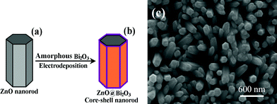
Metal oxides, such as Bi2O3, have been regarded as promising pseudocapacitive materials because the kinetics of charge–discharge processes is fast and they can generally be produced at lower cost and comparable to that of activated carbons. However, the poor electronic conductivity of metal oxides affects their high performances in supercapacitors. In order to overcome this shortcoming, herein single-crystal ZnO nanorod/amorphous metal oxide shells were investigated as electrodes for suprcapacitor applications. ZnO nanorods can function as efficient mechanical supports and electron conducting pathways because of its high stability, conductivity, and mechanical flexibility. As an example, 1D ZnO/Bi2O3 core/shell nanorods were synthesized for supercapacitor applications by a facile electrochemical deposition route. The synthesis of single-crystal ZnO/amorphous Bi2O3 core/shell nanorods was carried out by electrodeposition of Bi2O3 onto the surfaces of ZnO nanorods as illustrated in Fig. 1(a,b).
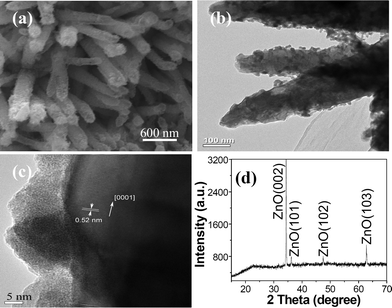
ZnO nanorods were firstly electrodeposited and the typical SEM image is shown in Fig. 1(c). The diameters and the lengths of ZnO nanorods were about 200 nm and 1 μm, respectively. TEM, HRTEM, SAED, and XRD results shown in Fig. S1† indicate ZnO nanorods have a single crystal structure and preferential growth in the [0001] direction. Then the electrodeposition of Bi2O3 shells was further carried out on the surfaces of ZnO nanorods, and Fig. 2(a) shows an SEM image of ZnO/Bi2O3 core/shell nanorods which clearly shows ZnO nanorods have uniform Bi2O3 covers. Furthermore, Bi2O3 covers favorably the surface of ZnO nanorods, and no Bi2O3 was packed the interspaces of the nanorods, which suggests Bi2O3 is preferentially deposited on the surface of ZnO nanorods. A TEM image of ZnO/Bi2O3 core/shell nanorods is shown in Fig. 2(b), which further shows Bi2O3 covers the surfaces of ZnO nanorods. A HRTEM image of ZnO/Bi2O3 core/shell nanorods is shown in Fig. 2(c), which shows the average thickness of the external Bi2O3 shell is about 14.5 nm. The HRTEM image shows the Bi2O3 shell has an amorphous structure. The inner ZnO nanorod shows a single-crystal structure and preferential growth in the [0001] direction. The lattice spacings can be calculated to be about 0.52 nm, which corresponds to the interplanar spacings of the wurtzite ZnO(0001). The XRD pattern of ZnO/Bi2O3 core/shell nanorods is shown in Fig. 2(d). The indexed diffraction peaks show a pure hexagonal phase of wurtzite-type ZnO (space group: P63mc) with lattice constants a = 3.249 Å and c = 5.206 Å, in accordance with the reported data (JCPDS, 36-1451). No Bi2O3 peak was observed in the XRD pattern. These results show Bi2O3 deposits on the surfaces of ZnO nanorods are amorphous, and this is accordant with the result of HRTEM.
ZnO/Bi2O3 core/shell nanorods are investigated for supercapacitor applications. The electrochemical performance of ZnO/Bi2O3 core/shell nanorods was firstly characterized by cyclic voltammetry (CV). CV is a useful tool to determine the faradaic and non-faradaic behaviours and evaluate the specific capacitance of the electrode materials. Fig. 3(a) shows the CV of the prepared ZnO/Bi2O3 core/shell nanorod electrode in 1.0 M Na2SO4 solution at a scan rate of 5 mV s−1 in the potential range from −1.0 to −0.1 V vs.SCE. In this CV curve, one pair of highly symmetrical redox peaks can be clearly observed, indicating good redox transitions between the different valence states of Bi2O3 and a good capacitive response from Bi2O3.13 Therefore, this is a redox supercapacitor by utilizing reversible Faradaic reactions occurring on the electrode surface. The specific capacitance (Csp) as an important parameter has been widely used to evaluate the performance of supercapacitors, and the Csp value of ZnO/Bi2O3 core/shell nanorods is calculated as about 233 F g−1, which is much larger than the specific capacitance reported for Bi2O3 nanocrystals (98 F g−1).13a
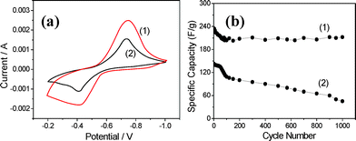 | ||
| Fig. 3 (a) CVs and (b) stabilities of (1) ZnO/Bi2O3 core/shell nanorod and (2) Bi2O3 nanoparticle electrodes in 1.0 M Na2SO4 electrolyte at a scan rate of 5 mV s−1. | ||
Fig. 3(b)(1) shows Csp variation of ZnO/Bi2O3 core/shell nanorods as a function of cycle number. The Csp of the ZnO/Bi2O3 core/shell nanorod electrode declined a little during the first 100 cycles but remained almost constant thereafter. The Csp decreased by a small amount during the early charging/discharging process may be attributed to the loss of active material caused by the dissolution and/or detachment. ZnO/Bi2O3 core/shell nanorods can withstand over 1000 cycles with no obvious decrease in the Csp values. However, Bi2O3 nanoparticles showed an obvious attenuation as shown in Fig. 3(a)(2), and their Csp values are much smaller than those of ZnO/Bi2O3 core/shell nanorods. Therefore, the deposited ZnO/Bi2O3 core/shell nanorods exhibit potential for long-term supercapacitor applications.
Herein the electrochemical route also can be used for the synthesis of inorganic/organic hybrid core/shell nanotubes that are rarely reported at present. Recently, inorganic/organic hybrid nanomaterials have attracted tremendous interest owing to their unique properties and potential applications in various fields including catalysis, sensing technology, optoelectronics, electromagnetism, etc.14–15 As an example, ZnO/PANI core/shell nanotubes are successfully fabricated in a high yield based on an electrochemical polymerization/etching process. The formation process of ZnO/PANI core/shell nanotubes is illustrated in Fig. 4. During the electrochemical polymerization, PANI is uniformly coated on the surface of ZnO nanorods, so it will effectively inhibit the corrosion of ZnO on the surface of nanorods. As a result, the ZnO dissolution rate on the surface of nanorods would be much slower than that in the center. So the selective dissolution affects the center part of ZnO nanorods preferentially along the c-axis, leaving the surfaces and resulting in tubular structures. Finally ZnO/PANI hybrid nanotubes were successfully prepared. Herein, ZnO dissolution is carried out in acidic deposition solution (pH = 1) via the following reaction:16
 | (1) |
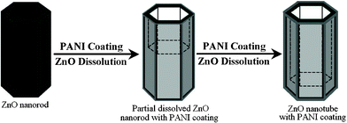 | ||
| Fig. 4 The formation mechanism of ZnO/PANI hybrid nanotubes. | ||
Fig. 5(a) shows an SEM image of the obtained ZnO/PANI composites. A typical magnified ZnO/PANI hybrid nanotube is shown in the inset, which shows the diameter of the ZnO/PANI nanotubes is about 120 nm, and the wall thickness is about 40 nm. A TEM image is shown in Fig. 5(b), which shows the diameter of the ZnO/PANI nanotubes is about 100–150 nm. An HRTEM image is shown in Fig. 5(c), which shows no lattice fringe was found in the outer shell region, indicating that the PANI shells are amorphous. The thickness of the PANI shell is about 1.5 nm. The inner core region clearly shows that the lattice fringes derive from crystalline ZnO and the lattice spacing is about 0.26 nm, which corresponds to the (0002) planar spacing of wurtzite-type ZnO. Fig. 5(d) shows the XRD pattern of ZnO/PANI hybrid nanotubes. Compared with the data in JCPDS No. 36-1451, the peak at 34.4° in the XRD pattern can be indexed to ZnO(002). A broad peak at 2θ = 19.5° appears, and it arises from momentum transfer perpendicular to the chain direction in PANI.19 This broad X-ray diffraction peak suggests that the PANI shell is amorphous, which agrees well with the above TEM results. The diffraction peaks at 43° and 50° can be attributed to the Cu substrate.
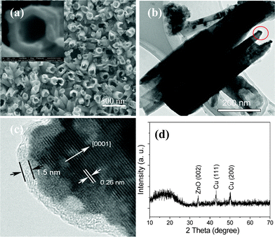 | ||
| Fig. 5 (a) SEM image, (b,c) TEM images, and (d) XRD pattern of ZnO/PANI core/shell nanotubes. | ||
The PL spectra of ZnO nanotubes and ZnO/PANI core/shell nanotubes are shown in Fig. 6. In Fig. 6(a), a near UV emission centred at 397 nm, the strong blue emissions at 450–500 nm, and a broad green band at 545 nm are clearly observed for ZnO/PANI core/shell nanotubes. Compared with that of pure ZnO nanotubes, the near UV emission of ZnO/PANI core/shell nanotubes shows an obvious red shift and intensity decrease as shown in Fig. 6, indicating the defects in the sample producing the strong orange emission and surface passivation by PANI layers. For ZnO/PANI core/shell nanotubes, the blue and green emissions can be attributed to electron–hole recombination at defect sites due to the electron transition from the shallow donor level of the intrinsic defect centers, such as interstitial zinc (Zni) and oxygen vacancy (VO), to the valence band.17 Compared with ZnO nanotubes, the enhancement of blue and green emissions of ZnO/PANI core/shell nanotubes can be explained as follows. As we all know, the valence band (VB) position of ZnO is lower than the HOMO of PANI, and accordingly the latter can act as an acceptor for photogenerated holes.18 So the holes in VB in ZnO can directly transfer to the HOMO of PANI when ZnO adsorbs UV light to generate electron–hole pairs.19 In addition, PANI is a good material for transporting holes, and the holes can be transferred easily to the surface.19 Therefore, the high efficiency of recombination of photogenerated holes with electrons will be achieved, leading to the prominent enhancement of blue and green emissions. The broadening of the visible emission in the PL spectrum of ZnO/PANI core/shell nanotubes in Fig. 6 can be ascribed to the abundant surface defects or impurities in the sample induced by the hybrid effect of PANI and ZnO. It is well known that defects and impurities on the surface of ZnO can provide new charge states, which contribute as visible luminescence centres and broaden the visible emission band. Therefore, PANI shells show important effects on the PL properties of ZnO nanotubes.
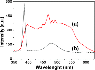 | ||
| Fig. 6 PL spectra of (a) ZnO/PANI nanotubes and (b) ZnO nanotubes. | ||
In summary, herein, we reported a facile electrochemical route to synthesize single-crystal ZnO/amorphous Bi2O3 core/shell nanorods and inorganic/organic ZnO/PANI core/shell nanotubes. The combination of single-crystal ZnO nanorods and amorphous Bi2O3 shells into 1D core/shell nanorod structures showed high specific capacitance and cycling life as supercapacitor electrodes. The PL measurements show PANI shells have an important effect on the red shift, the density decrease of UV emission, and the broadening of the visible emission of ZnO nanotubes. It is believed that the facile electrochemical route reported in this paper can be extended to synthesize the other ZnO-based core/shell nanostructures.
Acknowledgements
This work was supported by NSFC (21073240, 20873184, and 90923008), Guangdong Province (2008B010600040 and 9251027501000002), and the Fundamental Research Funds for the Central Universities (11lgzd14).References
- L. E. Greene, M. Law, B. D. Yuhas and P. Yang, J. Phys. Chem. C, 2007, 111, 18451–18456 CAS.
- X. Wang, H. Zhu, Y. Xu, H. Wang, Y. Tao, S. Hark, X. Xiao and Q. Li, ACS Nano, 2010, 4, 3302–3308 CrossRef CAS.
- X. Zhao, P. Wang and B. Li, Chem. Commun., 2010, 46, 6768–6770 RSC.
- (a) Y. Tak, S. J. Hong, J. S. Lee and K. Yong, J. Mater. Chem., 2009, 19, 5945 RSC; (b) P. Roy, C. Das, K. Lee, R. Hahn, T. Ruff, M. Moll and P. Schmuki, J. Am. Chem. Soc., 2011, 133, 5629–5631 CrossRef CAS.
- (a) T. Zhou, M. Lu, Z. Zhang, H. Gong, W. S. Chin and B. Liu, Adv. Mater., 2010, 22, 403–406 CrossRef CAS; (b) Y.-B. He, G.-R. Li, Z.-L. Wang, C.-Y. Su and Y.-X. Tong, Energy Environ. Sci., 2011, 4, 1288–1292 RSC.
- (a) B. Zhang, X. Yu, C. Ge, X. Dong, Y. Fang, Z. Li and H. Wang, Chem. Commun., 2010, 46, 9188 RSC; (b) J. Jang and Y. Kim, Chem. Commun., 2008, 4016–4018 RSC; (c) J. Zhao, L. Wu and J. Zhi, J. Mater. Chem., 2008, 18, 2459 RSC.
- (a) H. Wang, X.-H. Zhang, X. Fan, C.-S. Lee and S.-T. Lee, Chem. Commun., 2009, 5916 RSC; (b) X. Chen, H. Liu, X. Zhou and J. Hu, Nanoscale, 2010, 2, 2841–2846 RSC; (c) G.-R. Li, Z.-L. Wang, J.-H. Zhong, F.-L. Zheng and Y.-X. Tong, J. Mater. Chem., 2011, 21, 4217–4221 RSC.
- T. Zhou, M. Lu, Z. Zhang, H. Gong, W. S. Chin and B. Liu, Adv. Mater., 2010, 22, 403–406 CrossRef CAS.
- (a) A. S. Barnard, C. A. Feigl and S. P. Russo, Nanoscale, 2010, 2, 2294–2301 RSC; (b) Z. Bao, Z. Sun, M. Xiao, L. Tian and J. Wang, Nanoscale, 2010, 2, 1650–1652 RSC; (c) Y. Okuno, K. Nishioka, A. Kiya, N. Nakashima, A. Ishibashi and Y. Niidome, Nanoscale, 2010, 2, 1489–1493 RSC.
- (a) C. Corrado, M. Hawker, G. Livingston, S. Medling, F. Bridges and J. Z. Zhang, Nanoscale, 2010, 2, 1213–1221 RSC; (b) W. Schärtl, Nanoscale, 2010, 2, 829–843 RSC; (c) M. Zavelani-Rossi, M. G. Lupo, R. Krahne, L. Manna and G. Lanzani, Nanoscale, 2010, 2, 931–935 RSC; (d) S. K. Panda, A. Dev and S. Chaudhuri, J. Phys. Chem. C, 2007, 111, 5039–5043 CrossRef CAS.
- (a) S. Decker and K. J. Klabunde, J. Am. Chem. Soc., 1996, 118, 12465–12466 CrossRef CAS; (b) C. L. Carnes and K. J. Klabunde, Chem. Mater., 2002, 14, 1806 CrossRef CAS.
- N. Sharma, K. M. Shaju, G. V. S. Rao, B. V. R. Chowdari, Z. L. Dong and T. J. White, Chem. Mater., 2004, 16, 504 CrossRef CAS.
- (a) T. P. Gujar, V. R. Shinde, C. D. Lokhande and S.-H. Han, J. Power Sources, 2006, 161, 1479–1485 CrossRef CAS; (b) F.-L. Zheng, G.-R. Li, Y.-N. Ou, Z.-L. Wang, C.-Y. Su and Y.-X. Tong, Chem. Commun., 2010, 46, 5021 RSC.
- (a) H.-M. Xiong, D.-P. Xie, X.-Y. Guan, Y.-J. Tan and Y.-Y. Xia, J. Mater. Chem., 2007, 17, 2490 RSC; (b) H.-M. Xiong, Y. Xu, Q.-G. Ren and Y.-Y. Xia, J. Am. Chem. Soc., 2008, 130, 7522 CrossRef CAS; (c) H.-M. Xiong, Z.-D. Wang and Y.-Y. Xia, Adv. Mater., 2006, 18, 748–751 CrossRef CAS; (d) Y. Tu, L. Zhou, Y. Z. Jin, C. Gao, Z. Z. Ye, Y. F. Yang and Q. L. Wang, J. Mater. Chem., 2010, 20, 1594 RSC.
- (a) S. Xing, L. H. Tan, M. Yang, M. Pan, Y. Lv, Q. Tang, Y. Yang and H. Chen, J. Mater. Chem., 2009, 19, 3286 RSC; (b) L. Heng, D. Tian, L. Chen, J. Su, J. Zhai, D. Han and L. Jiang, Chem. Commun., 2010, 46, 1162–1164 RSC.
- H. Zeng, W. Cai, P. Liu, X. Xu, H. Zhou, C. Klingshirn and H. Kalt, ACS Nano, 2008, 2, 1661–1670 CrossRef CAS.
- (a) H. Zeng, G. Duan, Y. Li, S. Yang, X. Xu and W. Cai, Adv. Funct. Mater., 2010, 20, 561–572 CrossRef CAS; (b) H. Zeng, S. Yang and W. Cai, J. Phys. Chem. C, 2011, 115, 5038–5043 CrossRef CAS; (c) D. Banerjee, J. Y. Lao, D. Z. Wang, J. Y. Huang, Z. F. Ren, D. Steeves, B. Kimball and M. Sennett, Appl. Phys. Lett., 2003, 83, 2061 CrossRef CAS.
- H. Zhang, R. Zong and Y. Zhu, J. Phys. Chem. C, 2009, 113, 4605–4611 CAS.
- E. T. Kang, K. G. Neoh and K. L. Tan, Prog. Polym. Sci., 1998, 23, 277 CrossRef CAS.
Footnote |
| † Electronic Supplementary Information (ESI) available: Experimental details, TEM images, SAED pattern, XRD pattern, XPS spectra, and IR spectrum. See DOI: 10.1039/c1ra00110h/ |
| This journal is © The Royal Society of Chemistry 2011 |

