Cu2O microcrystals: a versatile class of self-templates for the synthesis of porous Au nanocages with various morphologies†
Xiaowang
Liu
*
College of Chemistry and Materials Science, Anhui Key Laboratory of Functional Molecular Solids, Anhui Key Laboratory of Molecule-based Materials, Anhui Normal University, Wuhu, 241000, P R China. E-mail: xwliu601@mail.ahnu.edu.cn
First published on 27th September 2011
Abstract
Design and synthesis of Au nanocages is one of the basic interests in the fabrication of nanoscale structures due to their attractive potentials in catalysis, medical science and so on. In most cases, spherical or cubic Au nanocages were fabricated using silica nanoparticles or Ag nanocubes as templates. In this article, another kind of versatile template, Cu2O microcrystals, has been employed to synthesize Au nanocages with various morphologies, such as cube, sphere, octahedron, truncated octahedron, cuboctahedron and concave cube morphologies. Surface modification of the templates, which is a necessary procedure in the synthesis of cage-shaped structures using a template-based strategy is avoided by this method because AuCl4− can be reduced spontaneously on the surfaces of the Cu2O microcrystals at room temperature. When the Cu2O microcrystals possess only one type of exposed planes, Au nanoparticles (NPs) are deposited homogeneously on the supports, etching out Cu2O portions in the as-prepared nanocomposites, with porous Au nanocages produced. However, if the Cu2O microcrystals have two kinds of exposed planes, such as (111) and (100), selective deposition of Au NPs was observed. Based on this phenomenon, cuboctahedral and truncated octahedral Au nanoframes were synthesized. Due to the porous structure of the as-prepared Au nanocages, the catalytic activity of cubic Au nanocages in the reduction of 4-nitrophenol by sodium borohydride is much higher than that of reported spongy Au nanocrystals.
Introduction
As an important member of the nanostructure family, nanocages with hollow interiors and porous walls have received paramount attention in both fundamental research and practical applications because of their potentials in controlled drug delivery,1 catalysis,2lithium-ion batteries,3 confined-space chemical reactors,4 biomedical diagnosis and therapy5 and so on.6 Generally speaking, the strategies used to synthesize nanocages are broadly categorized into two types: template-free and template-assistant methods.7 The former mainly contains ultrasonication, spray drying or pyrolysis, laser pyrolysis, etc. The features of this method are simplicity of operation, cost effectiveness and lack of elaborate equipment. However, their disadvantages include difficulties in controlling the size and shape of hollow structures, the understanding of the formation mechanisms and in exploring general strategies for nanocage synthesis. In contrast, the template-assistant method is one of the most controllable approaches for the synthesis of hollow nanostructures. Traditional template-based routes involve the growth of a shell of designed materials on various removable templates including monodispersed silica8 (polymer latex colloids9 or carbon microspheres10) to form core–shell composites and subsequently remove the template portions by calcinations or selective etching, generating hollow structures, whose inner structure is largely determined by the size and shape of the templates. In practice, functionalization of the template surface in the template-assisted method is necessary in order to overcome the incompatibility of the materials, as the desired heterogeneous nucleation on the existing template surface often competes with homogeneous nucleation of separate nanocrystals of the secondary material. Obviously, the functionalization process increases the complexity of the synthesis protocols, which leads to poor reproducibility of the strategy. Under these conditions, the newly developed self-templating methods are more attractive,11 such as the Ostwald ripening process, Kirkendall effect and galvanic replacement. These strategies eliminate the need for heterogeneous growth, making them more convenient to control the sizes and the shapes of the interior void of the products. Substantial effort has been devoted to exploring self-templated strategies for nanocage fabrication. Xia's group has systematically studied the synthesis of metal nanocages, such as Au, Pd, Pt and alloy, using Ag nanocubes as sacrificial templates.12 However, expanding suitable templates with a diversity in crystal morphology and a low cost for self-templated synthesis of metal nanocages is still of great interest.Cu2O is one of the prominent materials with abundant morphologies. Currently, a variety of Cu2O nanostructures, such as cube,13,14 octahedron,15 truncated octahedron,16 cuboctahedron,16 spherical particle,17 concave cube,18nanowire,19nanocage20 and nanoframes,21 have been synthesized by various approaches. If Cu2O nanostructures can be employed as templates for the synthesis of nanocages, the interior structures of the nanocages could be simply tuned by using different shaped Cu2O nano-/microcrystals. In this article, we report a facile self-templated approach for the synthesis of Au nanocages with controllable interior structures exploiting Cu2O microcrystals as sacrificial templates. Based on this strategy, Au nanocages with various regular interior shapes, such as cube, octahedron, sphere, concave cube, truncated octahedron and cuboctahedron have been successfully synthesized. This strategy has been demonstrated in detail using the synthesis of cubic Au nanocages as a model. The catalytic activity of the as-prepared cubic Au nanocages in the reduction of 4-nitrophenol by sodium borohydride has also been investigated showing that cubic porous Au nanocages have excellent catalytic activity, which is much higher than that of previously reported spongy Au nanocrystals. This enhanced catalytic activity is attributed to the porous feature of the Au nanocages, which can supply more reactive sites for the catalytic reaction in a short period of time.
Experimental
Materials
CuCl2·2H2O, CuSO4·5H2O, NaOH, NaBH4, sodium citrate, L-ascorbic acid, hydrazine hydrate, poly(vinylpyrrolidone), anhydrous sodium carbonate, glucose, N,N-dimethylformamide and HAuCl4 were purchased from Shanghai Chemical Reagent Co., Ltd. and used as received.Synthesis of Cu2O crystals
Synthesis of Cu2O–Au nanocomposites
The as-prepared Cu2O crystals with different shapes were dispersed into deionized water with a concentration ca. 174 mg mL−1 for the following usage. In a typical synthesis of cubic Cu2O–Au nanocomposites, 0.20 mL of HAuCl4 (0.50 mM) was injected into 0.10 mL cubic Cu2O colloid solution under vigorous stirring. The products were obtained by centrifuging after the reaction was kept at room temperature for several seconds. In order to control the size and density of the Au NPs on the Cu2O crystal surfaces, different concentrations of HAuCl4 solution, such as 1.25 and 2.50 mM, were injected into the Cu2O colloid solutions respectively under the same conditions. Other shaped Cu2O–Au core–shell nanocomposites were prepared in the similar way. In all experimental procedures, the volume of HAuCl4 solution injected was 0.20 mL unless stated otherwise.Synthesis of Au nanocages with different morphologies
Different shaped Au nanocages were prepared by etching corresponding core–shell nanocomposites in hydrochloric acid (1 M) for 10 min. The precipitates were harvested by centrifuging, and then were washed with distilled water and absolute ethanol several times. To tune the edge thickness of the cubic Au nanocages, 3.00 and 3.50 mM gold precursor was used in the synthesis of Cu2O–Au nanocomposites.Investigation of catalytic activity of cubic porous Au nanocages
To study the catalytic activity of the porous Au nanocages, 0.60 mg of the as-prepared cubic porous Au nanocages were introduced into a quartz cuvette containing 2.80 mL 7.1 × 10⁻⁵ M 4-nitrophenol solution, then a freshly prepared aqueous solution of NaBH4 (0.20 ml, 1.50 × 10⁻¹ M) was added. The changes in the reaction mixture were promptly monitored by UV-visible absorption spectroscopy.Characterization
XRD was carried out on a SHIMADZU XRD-6000 X-ray diffractometer with Cu-Kα radiation (λ = 1.54060 Å) in the 2θ range from 20 to 80°. TEM, high-resolution TEM (HRTEM) and energy-dispersive X-ray (EDX) spectrometry were performed using a JEM-2010 microscope operated at 200 kV. SEM images were taken with a Hitachi S-4800 field emission scanning electron microscope. UV-vis absorption spectra were performed on a Hitachi U-3010 spectrophotometer at room temperature. Specific surface areas were calculated by the Brunauer–Emmett–Teller (BET) method on a Micromeritics ASAP 2020 accelerated surface area analyzer at −196 °C. X-ray photoelectron spectroscopy (XPS) investigation of Au nanocages was conducted on an ESCALab220-XL electron spectrometer from VG Scientific using a monochromated Al Kα X-ray source.Results and discussion
Cu2O crystals with different shapes have been synthesized and characterized (Fig. S1 and S2†). All diffraction peaks of the as-prepared Cu2O crystals are consistent with those of cubic Cu2O, conforming the formation of phase-pure Cu2O. The synthesis of cubic Au nanocages has been employed as a model system for illustrating this strategy. Upon the addition of a HAuCl4 aqueous solution (0.50 mM, 0.20 mL), the initial orange color of the cubic Cu2O colloid solution (Fig. 1a) changed to a blackish color immediately (Fig. 1b). As shown in Fig. 2a, numerous NPs are homogeneously formed on the surfaces of the Cu2O cubes. The X-ray diffraction patterns of the products are in good agreement with the standard data of cubic Cu2O and the diffraction peaks of the (111) and (200) planes of the face-center cubic (fcc) gold (Fig. 2c), indicating that the NPs formed on the surfaces of the Cu2O are gold, that is, AuCl4− can be spontaneously reduced onto the surfaces of Cu2O at room temperature, as no additional reductive agent was added. TEM investigation (Fig. 2b) indicates that the diameter of the Au NPs is approximately 7–8 nm, and self-nucleated and isolated Au NPs are hardly observed. The in situreduction of AuCl4− in the presence of Cu2O is further confirmed by EDX measurements (Fig. 2d), from which Cu, O and Au elements are detected.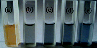 | ||
| Fig. 1 Cubic Cu2O crystal colloid solutions (a–d) upon adding HAuCl4 with different concentrations: (a) 0.00, (b) 0.50, (c) 1.25 and (d) 2.50 mM; (e) Cu2O–Au nanocomposites (2.50 mM HAuCl4 used) after being treated with HCl. | ||
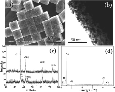 | ||
| Fig. 2 (a) SEM and (b) TEM images of cubic Cu2O microcrystals after being exposed to HAuCl4 (0.50 mM), (c) XRD patterns of cubic Cu2O crystals and as-prepared Cu2O–Au nanocomposites (* peaks refer to Au), and (d) the EDX spectrum of the obtained Cu2O–Au nanocomposites. | ||
The Cu2O colloid solutions become blacker upon enhancing the concentration of gold precursor (Fig. 1). The size and the density of the Au NPs on the surfaces of the Cu2O cubes are promoted gradually in the procedure of enhancing HAuCl4 concentration. For example, a higher gold precursor concentration (1.25 mM) contributed to a remarkable increase in the particle size (16 nm) and a significant enhancement in the particle density (Fig. 3a). Note that though there are increases in both the particle size and density of the Au NPs, the distribution of Au NPs is still discrete (Fig. 3b). If the concentration of the gold precursor was increased to 2.50 mM, cubic Cu2O–Au core–shell nanocomposites were produced and the shells are formed by aggregated Au NPs with diameters of about 30 nm (Fig. 3c and 3d). Au nanocages were fabricated by etching out Cu2O portions in the core–shell nanocomposites with the assistance of hydrochloric acid. SEM observation (Fig. 3e) from the broken cubes reveals that the Au nanocages have square and hollow interiors. This structure was further confirmed by the TEM analysis (Fig. 3f) due to the prominent contrast difference between the interiors and the shells. The edge thickness of the as-prepared Au nanocages is about 50 nm. The HRTEM image (Fig. 3g) of the Au nanocages illustrates that the shells of the nanocages are formed by conjugated Au nanocrystals, which is different from previous resports.24 The lattice fringes in the Au nanocages with values about 0.24 nm are well matched with the (111) crystal planes of Au. As the porous structure of the Au shells, gold precursor may diffuse into the shells and react with inner Cu2O crystals in the synthesis of Cu2O–Au nanocomposites when the concentration of gold precursor was increased further. As a result, the thicknesses of the final Au nanocages can be controlled by tuning the concentration of gold precursor. For example, the edge thicknesses of Au nanocages were increased to 55 and near 60 nm (Fig. S3†) when the concentration of gold precursor was enhanced to 3.00 and 3.50 mM, respectively. Oxygen, which completely derives from Cu2O, was not obviously observed in the products by EDX analysis (Fig. 3h), so the content of Cu in the Au nanocages is quite low. This point was confirmed by XPS measurements (Fig. S4†), which showed that the Cu atomic proportion in the products is about 0.66%. The Cu element in the final products may be attributed to the absorption of Au nanocages.
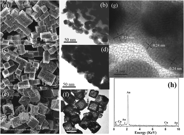 | ||
| Fig. 3 SEM and TEM images (a–d) of Cu2O cubes after being exposed to HAuCl4 with different concentrations, (a–b) 1.25, (c–d) 2.50 mM; SEM (e), TEM (f), HRTEM (g) images and EDX (h) of Cu2O–Au nanocomposites after being treated with HCl. | ||
The changes (a–d in Fig. 4) in cubic Cu2O crystal colloid solutions upon the injection of HAuCl4 solutions with different concentrations were examined by UV-vis absorption spectroscopy. Pure Cu2O cubes (a) show an absorption band at 485–490 nm and multiple absorption bands in the near-infrared regions, the former is attributed to the absorption of Cu2O cubes and the latter corresponds to light scattering caused by the particles.13 Upon the injection of HAuCl4 solution (0.50 mM), the characteristic absorption of Cu2O as well as the scattering peaks decreased obviously (b). These peaks decreased further when we enhanced the concentration of gold precursor to 1.25 (c) or 2.50 mM (d). From the TEM measurements on Cu2O cubes and cubic Cu2O–Au nanocomposites, they possess similar sizes; however, the intensity of the scattering bands of the nanocomposites is much lower than that of Cu2O crystals. This phenomenon can be explained by the fact that partial scattering light is adsorbed by the Au NPs on the planes of the Cu2O crystals. After the removal of the Cu2O portions, Au nanocages (f) show a broad and red-shifted absorption feature as a result of plasmon coupling.
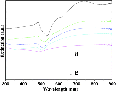 | ||
| Fig. 4 UV-vis spectra of cubic Cu2O crystals (a) and Cu2O–Au nanocomposites (b–e) prepared using HAuCl4 with different concentrations: (b) 0.50, (c) 1.25 and (d) 2.50 mM; and (e) cubic Au nanocages. | ||
The driving force for the formation of Au NPs on the surfaces of the Cu2O microcrystals is attributed to the difference in reduction potential between Cu2O/Cu2+ (0.203 V, vs.SHE) and AuCl4−/Au pair (0.99 V).25 Once AuCl4− is in contact with the Cu2O cubes in aqueous solution, it will be immediately reduced by the supports and nucleated rapidly on their surfaces to grow into clusters and further into NPs. This point is confirmed by the fact that no Au NPs were produced when Cu2O crystals were replaced by CuO NPs (Fig. S5†). Furthermore, the low lattice mismatch between Au and Cu2O also favors the growth of Au NPs on the Cu2O crystals. The lattice fringes (Fig. S6†) in the cubic Cu2O–Au nanocomposites with values of about 0.21 nm and 0.20 nm can be indexed as the (200) crystal plane of Cu2O and the (200) facet of Au. Both planes at the interface are parallel to each other, implying that Au NPs are epitaxially grown on the (200) planes of Cu2O, which is consistent with a previous observation in Au–Cu2O core–shell heterostructures.26
Based on the above discussion, this strategy is expected to extend to synthesize Au nanocages with other morphologies and the results are shown in Fig. 5. When Cu2O crystals with other shapes, such as octahedron, spherical particle, concave cube, truncated octahedron and cuboctahedron, were employed as templates, Au nanocages with corresponding interior shapes were obtained. An interesting phenomenon that should be noted here is that for the Cu2O microcrystals with only one kind of exposed surfaces, Au NPs were undoubtedly formed on all planes homogeneously, Au nanocages were synthesized by etching such core–shell nanocomposites in the presence of HCl. However, for those crystals with different kinds of exposed facets, such as truncated octahedron and cuboctahedron, preferential formation of Au NPs on the (111) planes of those crystals is observed (Fig. S7†),27etching preformed core–shell nanocomposites (1.25 mM HAuCl4 was used) can favor the formation of Au nanoframes (Fig. 5i–5j and 5k–5l) with preserved shapes. Preferential formation of Au NPs on the (111) facets in the presence of (100) facets is due to the fact that surface atoms of the (111) facets have more dangling bonds, resulting in higher surface energy.18,21,28 However, if the concentration of HAuCl4 was increased further, perfect core–shell nanocomposites were also obtained. Removal of Cu2O in such nanocomposites, truncated octahedral and cuboctahedral Au nanocages were synthesized. Taking the formation of cubic Au nanocages as an illustration, the detailed schematic procedures are shown in Fig. 5o.
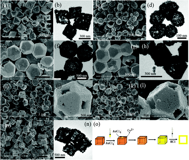 | ||
| Fig. 5 SEM and TEM images of Au nanocages prepared using Cu2O crystals as self-templates: (a, b) octahedron, (c, d) spherical NP, (e, f) cuboctahedron, (g, h) truncated octahedron, (m, n) concave cube; (i, j) and (k, l) SEM images with different magnifications of cuboctahedral and truncated octahedral Au nanoframes; (o) schematic procedures for the synthesis of cubic Au nanocages. | ||
The porous hollow structures are expected to supply enhanced catalytic activity in chemical reactions due to the presence of two types of surfaces that increase the surface area available for the catalytic reaction. To study the catalytic performance of the as-prepared porous Au nanocages, the reduction of 4-nitrophenol by sodium borohydride has been explored as a test reaction. After the addition of sodium borohydride, the absorption peak shifts from 315 nm to 400 nm prominently because of the formation of 4-nitrophenolate.28 The absorption maximum of this solution didn't change obviously, even if it was kept at room temperature for more than 24 h (Fig. 6a). This phenomenon implies that the reduction procedure can hardly proceed without catalysts. However, under the same condition, once only 0.60 mg of Au nanocages was added to the 4-nitrophenol solution, the reduction of 4-nitrophenolate proceeds quickly and the absorption peak centered at 400 nm completely disappeared within 10 min. Time-dependent UV-vis absorption spectra of the mixture shows the successive decrease in the absorption centered at 400 nm and the gradual development of a new peak at 300 nm, which is attributed to the absorption of 4-aminophenol.29 If only Au nanocages were added into the 4-nitrophenol solution, no visible change was detected, which means that H+ derived from either HAuCl4 or HCl in the final product were completely removed through washing with distilled water and absolute ethanol as the color change of 4-nitrophenol is pH dependent. However, UV-vis absorption analysis indicated that the peak located at 315 nm reduced slightly as a result of the absorption of Au nanocages (Fig. S8†). Considering the reductant concentration, BH4−, is much higher than that of 4-nitrophenol, the reaction should be of first order with regard to the reactant. A linear relationship between lnA400 (A is the absorbance at 400 nm) and reaction time is obtained in the reduction of 4-nitrophenol in the presence of porous Au nanocages, which match well with first-order reaction kinetics. As measured from the plot of lnA400vs. time (inset in Fig. 6b), the rate constant of this reaction is about 3.78 × 10⁻³ sec−1, which is much larger than that of spongy Au nanocrystals.30 This enhancement is very significant, especially when the catalyst amount, only a tenth of that of spongy Au nanocrystals, is taken into account. Though the BET surface area of the Au nanocages was calculated to be as much as approximately 2.90 m2 g−1, which is much lower than that of spongy Au nanocrystals as a result of the larger diameter of the Au nanoparticles in the Au nanocages, the pronounced catalytic activity of the porous Au nanocages can be understood by the explanation that large reactive surfaces will serve to the reduction reaction immediately when the porous Au nanocages are added to the reaction mixture. Under the same conditions, 4-nitrophenol will take more time to diffuse into the channels of the spongy Au nanocrystals, which subsequently leads to a lower rate constant.31 It is important to note that H2 bubbles were produced continually from the solution and were adhered to the surfaces of the Au nanocages, driving the aggregation of the Au nanocages. This point was confirmed by TEM measurements on the used Au nanocages (Fig. S9†).
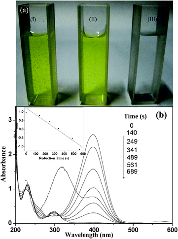 | ||
| Fig. 6 (a) 4-Nitrophenol solution kept at room temperature for 24 h in the presence (I) and absence (II) of sodium borohydride, and in the presence of both sodium borohydride and cubic Au nanocages for 10 min (III), the black precipitation at the bottom of cuvette III is Au nanocages; (b) successive UV-vis absorption spectra of 4-nitrophenol solution reduced by sodium borohydride in the presence of cubic Au nanocages. The inset shows the plot indicating the variation of lnA400 (absorbance at 400 m) vs. time. | ||
Conclusions
In conclusion, Au nanocages with various shapes have been synthesized by exploring Cu2O microcrystals as self-templates. The reduction potential difference in the electrode pairs of Cu2O/Cu2+ and AuCl4−/Au and less lattice mismatches between (100) planes of Cu2O and (100) facets of Au contribute to the spontaneous reduction of AuCl4− and deposition of Au NPs on the Cu2O surfaces. By carefully controlling the reaction conditions and choosing proper templates, Au nanoframes can even be obtained, such as truncated octahedron and cuboctahedron. Due to the porous structure of the Au shells and the shorter diffusion time for 4-nitrophenol, cubic Au nanocages have a higher catalytic activity than that of spongy Au nanocrystals in the reduction of 4-nitrophenol in the presence of NH4−. This has enriched the strategy for the synthesis of Au nanocages and can be expanded to synthesize other noble metal nanocages or nanoframes.Acknowledgements
This work was supported by National Natural Science Foundation (No. 21001006) of P. R. China, and the State Education Ministry (EYTP, SRF for ROCS, SRFDP 20070370001).References
- (a) Y. F. Zhu, J. L. Shi, W. H. Shen, X. P. Dong, J. W. Feng, M. L. Ruan and Y. S. Li, Angew. Chem., Int. Ed., 2005, 44, 5083 CrossRef CAS; (b) W. Wei, G.-H. Ma, G. Hu, Di. Yu, T. Mcleish, Z.-G. Su and Z.-Y. Shen, J. Am. Chem. Soc., 2008, 130, 15808 CrossRef CAS; (c) J. Yang, J. Lee, J. Kang, K. Lee, J.-S. Suh, H.-G. Yoon, Y.-M. Huh and S. Haam, Langmuir, 2008, 24, 3417 CrossRef CAS; (d) J. Liu, S. Z. Qiao, S. B. Hartono and G. Q. Lu, Angew. Chem., Int. Ed., 2010, 49, 4981 CrossRef CAS.
- (a) C. W. Yen, M. A. Mahmoud and M. A. El-Sayed, J. Phys. Chem. A, 2009, 113, 4340 CrossRef CAS; (b) M. A. Mahmoud, F. Saira and M. A. El-Sayed, Nano Lett., 2010, 10, 3764 CrossRef CAS; (c) J. Zeng, Q. Zhang, J. Chen and Y. Xia, Nano Lett., 2010, 10, 30 CrossRef CAS; (d) H.-P. Liang, H.-M. Zhang, J.-S. Hu, Y.-G. Guo, L.-J. Wan and C.-L. Bai, Angew. Chem., Int. Ed., 2004, 43, 1540 CrossRef CAS.
- (a) X. W. Lou, C. M. Li and L. A. Archer, Adv. Mater., 2009, 21, 2536 CrossRef CAS; (b) X. M. Yin, C. C. Li, M. Zhang, Q. Y. Hao, S. Liu, L. B. Chen and T. H. Wang, J. Phys. Chem. C, 2010, 114, 8084 CrossRef CAS; (c) S. Gao, S. Yang, J. Shu, S. Zhang, Z. Li and K. Jiang, J. Phys. Chem. C, 2008, 112, 19324 CrossRef CAS; (d) J. S. Chen, C. M. Li, W. W. Zhou, Q. Y. Yan, L. A. Archer and X. W. Lou, Nanoscale, 2009, 1, 280 RSC.
- (a) S. Ding, J. S. Chen, G. Qi, X. Duan, Z. Wang, E. P. Giannelis, L. A. Archer and X. W. Lou, J. Am. Chem. Soc., 2011, 133, 21 CrossRef CAS.
- (a) J. Chen, M. Yang, Q. Zhang, E. C. Cho, C. M. Cobley, C. Kim, C. Glaus, L. V. Wang, M. J. Welch and Y. Xia, Adv. Funct. Mater., 2010, 20, 3684 CrossRef CAS; (b) C. M. Cobley, J. Chen, E. C. Cho, L. V. Wang and Y. Xia, Chem. Soc. Rev., 2011, 40, 44 RSC; (c) C. Kim, E. C. Cho, J. Chen, K. H. Song, L. Au, C. Favazza, Q. Zhang, C. M. Cobley, F. Cao, Y. Xia and L. V. Wang, ACS Nano, 2010, 4, 4559 CrossRef CAS.
- (a) P. M. Arnal, M. Comotti and F. Schüth, Angew. Chem., Int. Ed., 2006, 45, 8224 CrossRef CAS.
- (a) Y. Ma and L. Qi, J. Colloid Interface Sci., 2009, 335, 1 CrossRef CAS; (b) X. W. Lou, L. A. Archer and Z. Yang, Adv. Mater., 2008, 20, 3987 CrossRef CAS.
- (a) P. M. Arnal, C. Weidenthaler and F. Schüth, Chem. Mater., 2006, 18, 2733 CrossRef CAS; (b) D. Son, A. Wolosiuk and P. V. Braun, Chem. Mater., 2009, 21, 628 CrossRef CAS; (c) X. Xu and S. A. Asher, J. Am. Chem. Soc., 2004, 126, 7940 CrossRef CAS; (d) N. Du, H. Zhang, J. Chen, J. Sun, B. Chen and D. Yang, J. Phys. Chem. B, 2008, 112, 14836 CrossRef CAS.
- (a) F. Caruso, R. A. Caruso and H. Möhwald, Chem. Mater., 1999, 11, 3309 CrossRef CAS; (b) X. Wu, Y. Tian, Y. Cui, L. Wei, Q. Wang and Y. Chen, J. Phys. Chem. C, 2007, 111, 9704 CrossRef CAS; (c) H. Zou, S. Wu and J. Shen, Langmuir, 2008, 24, 10453 CrossRef CAS.
- (a) X. Sun, J. Liu and Y. Li, Chem.–Eur. J., 2006, 12, 2039 CrossRef CAS; (b) Y. Zhu, E. Kockrick, T. Ikoma, N. Hanagata and S. Kaskel, Chem. Mater., 2009, 21, 2547 CrossRef CAS; (c) X. Lai, J. Li, B. A. Korgel, Z. Dong, Z. Li, F. Su, J. Du and D. Wang, Angew. Chem., Int. Ed., 2011, 50, 2738 CrossRef CAS.
- Q. Zhang, W. Wang, J. Goebl and Y. Yin, Nano Today, 2009, 4, 494 CrossRef CAS.
- (a) S. E. Skrabalak, L. Au, X. Li and Y. Xia, Nat. Protoc., 2007, 2, 2182 CrossRef CAS; (b) S. E. Skrabalak, J. Chen, Y. Sun, X. Lu, L. Au, C. Cobley and Y. Xia, Acc. Chem. Res., 2008, 41, 1587 CrossRef CAS.
- C.-H. Kuo, C.-H. Chen and M. H. Huang, Adv. Funct. Mater., 2007, 17, 3773 CrossRef CAS.
- (a) L. Gou and C. J. Murphy, Nano Lett., 2003, 3, 231 CrossRef CAS; (b) L. Gou and C. J. Murphy, J. Mater. Chem., 2004, 14, 735 RSC; (c) D. Wang, M. Mo, D. Yu, L. Xu, F. Li and Y. Qian, Cryst. Growth Des., 2003, 3, 717 CrossRef CAS; (d) X. Liang, L. Gao, S. Yang and J. Sun, Adv. Mater., 2009, 21, 2068 CrossRef CAS; (e) Y. Sui, W. Fu, H. Yang, Y. Zeng, Y. Zhang, Q. Zhao, Y. Li, X. Zhou, Y. Leng, M. Li and G. Zou, Cryst. Growth Des., 2010, 10, 99 CrossRef CAS; (f) K. X. Yao, X. M. Yin, T. H. Wang and H. C. Zeng, J. Am. Chem. Soc., 2010, 132, 6131 CrossRef CAS.
- (a) H. Xu, W. Wang and W. Zhu, J. Phys. Chem. B, 2006, 110, 13829 CrossRef CAS; (b) H. Li, R. Liu, R. Zhao, Y. Zheng, W. Chen and Z. Xu, Cryst. Growth Des., 2006, 6, 2795 CrossRef CAS.
- C.-H. Kuo and M. H. Huang, J. Phys. Chem. C, 2008, 112, 18355 CAS.
- (a) M. Pang and H. C. Zeng, Langmuir, 2010, 26, 5963 CrossRef CAS; (b) J. Zhang, J. Liu, Q. Peng, X. Wang and Y. Li, Chem. Mater., 2006, 18, 867 CrossRef CAS.
- H. Y. Zhao, Y. F. Wang and J. H. Zeng, Cryst. Growth Des., 2008, 8, 3731 CAS.
- (a) D. P. Singh, N. R. Neti, A. S. K. Sinha and O. N. Srivastava, J. Phys. Chem. C, 2007, 111, 1638 CrossRef CAS; (b) Y. Tan, X. Xue, Q. Peng, H. Zhao, T. Wang and Y. Li, Nano Lett., 2007, 7, 3723 CrossRef CAS.
- (a) C. Lu, L. Qi, J. Yang, X. Wang, D. Zhang, J. Xie and J. Ma, Adv. Mater., 2005, 17, 2562 CrossRef CAS; (b) S. Jiao, L. Xu, K. Jiang and D. Xu, Adv. Mater., 2006, 18, 1174 CrossRef CAS; (c) J. J. Teo, Y. Chang and H. C. Zeng, Langmuir, 2006, 22, 7369 CrossRef CAS; (d) Y. Chang, J. J. Teo and H. C. Zeng, Langmuir, 2005, 21, 1074 CrossRef CAS; (e) Z. Wang, X. Chen, J. Liu, M. Mo, L. Yang and Y. Qian, Solid State Commun., 2004, 130, 585 CrossRef CAS; (f) H. Xu and W. Wang, Angew. Chem., Int. Ed., 2007, 46, 1489 CrossRef CAS; (g) C. H. Kuo and M. H. Huang, J. Am. Chem. Soc., 2008, 130, 12815 CrossRef CAS.
- Y. Sui, W. Fu, Y. Zeng, H. Yang, Y. Zhang, H. Chen, Y. Li, M. Li and G. Zou, Angew. Chem., Int. Ed., 2010, 49, 4282 CrossRef CAS.
- Z. Wang, H. Wang, L. Wang and L. Pan, J. Phys. Chem. Solids, 2009, 70, 719 CrossRef CAS.
- Z. Wang, H. Wang, L. Wang and L. Pan, Cryst. Res. Technol., 2009, 44, 624 CrossRef CAS.
- (a) Y. Sun and Y. Xia, J. Am. Chem. Soc., 2004, 126, 3892 CrossRef CAS; (b) J. Chen, B. Wiley, J. McLellan, Y. Xiong, Z.-Y. Li and Y. Xia, Nano Lett., 2005, 5, 2058 CrossRef CAS.
- (a) G. Millazzo, S. Caroli, in Tables of Standard Electrode Potentials, John Wiley & Sons Inc., New York, 1978 Search PubMed.
- C. H. Kuo, T.-E. Hua and M.-H. Huang, J. Am. Chem. Soc., 2009, 131, 17871 CrossRef CAS.
- X.-W. Liu, Langmuir, 2001, 27, 9100 Search PubMed.
- J. Y. Ho and M. H. Huang, J. Phys. Chem. C, 2009, 113, 14159 CAS.
- N. Pradhan, A. Pal and T. Pal, Langmuir, 2001, 17, 1800 CrossRef CAS.
- M. H. Rashid, R. R. Bhattacharjee, A. Kotal and T. K. Mandal, Langmuir, 2006, 22, 7141 CrossRef CAS.
- K. Esumi, K. Miyamoto and T. J. Yoshimura, J. Colloid Interface Sci., 2002, 254, 402 CrossRef CAS.
Footnote |
| † Electronic supplementary information (ESI) available: characterization of Cu2O microcrystals, SEM images of CuO nanocrystals before and after addition of HAuCl4 solution, characterization of Au nanocages by TEM and XPS, selective deposition of Au NPs on Cu2O truncated octahedra and cuboctahedra, UV-absorption spectra of 4-nitrophenol before and after addition of Au nanocages and TEM measurement of used Au nanocages. See DOI: 10.1039/c1ra00250c |
| This journal is © The Royal Society of Chemistry 2011 |
