DOI:
10.1039/C1RA00605C
(Paper)
RSC Adv., 2011,
1, 1482-1488
Nanoparticle decorated fibrous silica membranes exhibiting biomimetic superhydrophobicity and highly flexible properties
Received
18th August 2011
, Accepted 8th September 2011
First published on 21st October 2011
Abstract
Inspired by the self-cleaning lotus leaf, here we report the fabrication of flexible fluorinated silica nanofibrous membranes with biomimetic non-wettable surfaces by electrospinning blend solutions of poly(vinyl alcohol) (PVA) and silica gel in the presence of silica nanoparticles, followed by calcination and fluoroalkylsilane (FAS) modification. The resultant silica nanofibers exhibited a lotus-leaf-like structure with numerous nanoparticles decorated on the fiber surfaces due to the rapid phase separation in electrospinning and calcination processing. The content of silica nanoparticles incorporated into the fibers proved to be the key factor affecting the fiber surface morphology and wettability. The fluorinated silica fibrous membranes containing 38.8 wt% silica nanoparticle showed the highest water contact angle (WCA) of 155°, oil contact angle (OCA) of 143°, orange juice contact angle (OJCA) of 142°, and milk contact angle (MCA) of 137°. Additionally, the fluorinated silica membranes exhibited good flexibility and the flexibility was also characterized by KES-FB2S. We believe that this new class of inorganic membranes is particularly promising for the development of high-temperature filtration, novel easy-clean coatings, and even flexible electronics.
Introduction
Nature has built a tremendous number of fascinating materials and structured surfaces with excellent surface wettability.1 Biomimetic investigations have demonstrated that some natural phenomena, such as the self-cleaning effect of lotus and silver ragwort leaves,2,3 the superhydrophobic forces exerted by a water strider's leg,4 the anisotropic de-wetting behavior of rice leaves and waterfowl feathers,5,6 are related to their unique micro- and nanostructured surfaces. Among them, the lotus leaf is one of the most well-known and studied examples due to its self-cleaning effect, and exhibits a high water contact angle of around 161° and a small sliding angle of about 2° (Fig. 1a).7,8 The unique superhydrophobic self-cleaning properties of lotus leaves can be attributed to a cooperation of the hydrophobic wax-like material and special micro- and nanoscale hierarchical architectures in the form of micrometre-scale papillae on their surfaces (Fig. 1b).9 To fabricate such surfaces, various modern technologies such as template synthesis, phase separation, electrochemical deposition, electrohydrodynamics, sol–gel methods, chemical vapor deposition, self-assembly, and so on, have been developed for the synthesis of advanced materials with controlled structures.2,10–12 Fundamentally, progress in the classical models and recent experimental research have indicated that surface structure or roughness with a length on the micrometre or nanometre scale play a key role in the realization of superhydrophobic surfaces.13,14
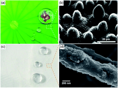 |
| | Fig. 1 (a) Lotus leaves show superhydrophobic properties. Reprinted with permission from © 2009 http://www.yiitoo.com. (b) SEM image of the surface structures on the lotus leaf.35 Reproduced with permission from ref. 35. © 1997 Springer-Verlag. (c) Several water droplets placed on SiO2 membranes. (d) FE-SEM image of an inorganic silica fiber with a lotus-leaf-like structure. | |
Electrospinning has emerged as one of the most popular methods for the fabrication of micro- and nanofibrous materials with controllable compositions and structures in recent years,15–18 and therefore provides excellent prospects for the construction of biomimetic superhydrophobic surfaces. Porous nanofiber/microsphere composite films biologically inspired to imitate the self-cleaning properties of the lotus leaf have been formed by finely controlling the concentration of a polystyrene solution during electrospinning.2 Yoon et al.19 prepared a biomimetically designed superhydrophobic poly(ε-caprolactone) surface through a modified electrostatic process. The fabricated surface exhibits a micron-sized pyramid structure consisting of accumulated droplets and nanofibers. Ma et al.20 have also shown higher contact angles and lower hysteresis using fibers decorated with nanometre-sized pores or particles. On the other hand, inorganic materials are potentially important for applications in many areas including electronics, photonics, mechanics, and sensing. Modifying the surface wettability of inorganic materials is also important in many situations.21 Over the years, considerable effort has been extended to fabricating superhydrophobic surfaces based on inorganic fibers, including SiO2,22ZnO,21TiO2,23 and Fe3O4-filled carbon nanofibers,24etc. But the brittleness of inorganic fibrous membranes significantly limited their practical applications. Recently, our group has demonstrated the fabrication of flexible, high-heat-resistant, and amphiphobic silica membranes by surface modification of bead-on-string structured nanofibrous silica membranes.25 However, the smooth fiber surface is sometimes a limiting factor to further enhancing the contact angles and thus prevents their practical use. To date, as far as we know, a fundamental understanding of how to increase their surface superhydrophobicity whilst retaining their flexibility remains a very important and challenging issue.
In this contribution, we extend our earlier work by developing a new class of flexible inorganic nanofibrous membranes with non-wettable surfaces by the combination of electrospinning, calcination, and surface modification techniques. By systematically varying the content of added silica nanoparticles into the PVA/silica gel solutions, superhydrophobic inorganic silica fibers with a lotus-leaf-like structure can be facilely prepared (Fig. 1c–d). The resultant fluoroalkylsilane (FAS) modified inorganic silica membranes exhibit good flexibility and the flexibility was also demonstrated by a KES-FB2S test. Moreover, the surface wettability of the fluorinated membranes was also investigated regarding their morphologies and various liquids.
Experimental
Materials
The starting materials included poly(vinyl alcohol) (PVA, Mw 88![[thin space (1/6-em)]](https://www.rsc.org/images/entities/char_2009.gif) 000, Aladdin Chemical Co., China), tetraethyl orthosilicate (TEOS, Lingfeng Chemical Co., Ltd., China), phosphoric acid (85 wt%), silica nanoparticles (diameter of particles, 7–40 nm; specific surface area, 120 m2 g−1; Aladdin), fluoroalkylsilane (FAS, Gelest Inc., USA), hexane (Sinopharm Chemical Reagent Co., Ltd., China), oil (Arowana Salad Oil), milk (Yili Pure Milk), orange juice (Orange Unified), and pure water.
000, Aladdin Chemical Co., China), tetraethyl orthosilicate (TEOS, Lingfeng Chemical Co., Ltd., China), phosphoric acid (85 wt%), silica nanoparticles (diameter of particles, 7–40 nm; specific surface area, 120 m2 g−1; Aladdin), fluoroalkylsilane (FAS, Gelest Inc., USA), hexane (Sinopharm Chemical Reagent Co., Ltd., China), oil (Arowana Salad Oil), milk (Yili Pure Milk), orange juice (Orange Unified), and pure water.
Preparation of precursor solutions
11 wt% PVA was prepared from PVA powder and pure water at 80 °C with vigorous stirring. A silica gel with the molar composition of TEOS![[thin space (1/6-em)]](https://www.rsc.org/images/entities/char_2009.gif) :
:![[thin space (1/6-em)]](https://www.rsc.org/images/entities/char_2009.gif) H3PO4
H3PO4![[thin space (1/6-em)]](https://www.rsc.org/images/entities/char_2009.gif) :
:![[thin space (1/6-em)]](https://www.rsc.org/images/entities/char_2009.gif) H2O = 1
H2O = 1![[thin space (1/6-em)]](https://www.rsc.org/images/entities/char_2009.gif) :
:![[thin space (1/6-em)]](https://www.rsc.org/images/entities/char_2009.gif) 0.01
0.01![[thin space (1/6-em)]](https://www.rsc.org/images/entities/char_2009.gif) :
:![[thin space (1/6-em)]](https://www.rsc.org/images/entities/char_2009.gif) 11 was prepared by hydrolysis and polycondensation by dropwise addition of H3PO4 to TEOS with stirring at room temperature for 6 h. Then 10 g silica gel was dropped slowly into 10 g PVA solutions and stirred for another 6 h. Then 0, 0.16, 0.32 and 0.64 g silica nanoparticles were added into the PVA/silica gel solutions, respectively. Thus, viscous composite solutions containing different contents of added silica nanoparticles (0, 0.79, 1.58 and 3.16%), used as the electrospinning solutions, were obtained.
The setup for electrospinning deposition fibrous membranes on the grounded collector is depicted in Fig. 2. The composite solutions were loaded into a syringe that was attached to a high-voltage power supply (DW-P303-1ACD8, Tianjin Dongwen High Voltage Co., China) that was capable of generating voltages up to 18 kV. A syringe pump (LSP02-1B, Baoding Longer Precision Pump Co., Ltd., China) was used to regulate the flow of the solutions at 1 mL h−1. The fibrous membranes were deposited on the aluminium foil-covered grounded metallic rotating roller at a 15 cm tip-to-collector distance. All the experiments were conducted at 24 °C with a relative humidity of 45%.
11 was prepared by hydrolysis and polycondensation by dropwise addition of H3PO4 to TEOS with stirring at room temperature for 6 h. Then 10 g silica gel was dropped slowly into 10 g PVA solutions and stirred for another 6 h. Then 0, 0.16, 0.32 and 0.64 g silica nanoparticles were added into the PVA/silica gel solutions, respectively. Thus, viscous composite solutions containing different contents of added silica nanoparticles (0, 0.79, 1.58 and 3.16%), used as the electrospinning solutions, were obtained.
The setup for electrospinning deposition fibrous membranes on the grounded collector is depicted in Fig. 2. The composite solutions were loaded into a syringe that was attached to a high-voltage power supply (DW-P303-1ACD8, Tianjin Dongwen High Voltage Co., China) that was capable of generating voltages up to 18 kV. A syringe pump (LSP02-1B, Baoding Longer Precision Pump Co., Ltd., China) was used to regulate the flow of the solutions at 1 mL h−1. The fibrous membranes were deposited on the aluminium foil-covered grounded metallic rotating roller at a 15 cm tip-to-collector distance. All the experiments were conducted at 24 °C with a relative humidity of 45%.
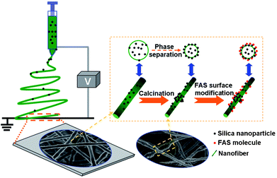 |
| | Fig. 2 Schematic diagram illustrating the processing steps in the fabrication of lotus-leaf-like structured fluorinated silica nanofibers. | |
Fabrication of FAS modified fibrous silica membranes
The composite fibrous samples were calcined at 800 °C in air for 2 h to remove the organic components. The inorganic silica fibrous membranes contained two parts of silica particles (silica hydrolyzed from TEOS and silica nanoparticles dispersed in the composite solutions). Accordingly, the content of silica nanoparticles in the resultant four silica fibrous membranes was 0, 9.7, 19.4, and 38.8 wt%, respectively. Surface modification of the obtained inorganic samples was carried out by immersing the samples in 3 wt% FAS in hexane for 20 h at room temperature. Then the samples were dried in air and heated at 100 °C for 1 h in an oven. The Si atom of the FAS molecule connects to three methoxy groups and one long fluorocarbon chain. The methoxy group is easily hydrolyzed to a Si–OH group, which reacts with an active –OH group located on the surface of the silica fibers and thus forms a covalent Si–O–Si bond. Through the strong Si–O–Si bond, the FAS molecule can be bonded tightly with silica fibers.
Characterization
The morphology of the fibrous membranes was examined by scanning electron microscopy (SEM, S-3000N, Hitachi Ltd., Japan). The diameter of the fibers was measured using an image analyser (Adobe Photoshop CS2). The surface topography of the silica fibrous membranes was assessed by noncontact profilometry using an interferometer profiler (Wyko-Veeco, model NT9100, USA). The topographic roughness parameter average roughness (Ra) was determined for each sample. Fourier transform infrared (FT-IR) spectra were recorded using a Nicolet 8700 FT-IR spectrometer in the wavenumber range of 4000–400 cm−1. The water contact angle (WCA), oil contact angle (OCA), orange juice contact angle (OJCA), and milk contact angle (MCA) of resultant samples were measured with a contact angle meter (Contact Angle System OCA40, Dataphysics Co., Germany). Measurements from at least six droplets of 12 μL liquids (water, oil. orange juice and milk) were averaged. The Brunauer–Emmett–Teller (BET) surface area was characterized using a surface area analyzer (ASAP 2010, micromeritics Co., USA). The bending rigidity (B) was characterized by a KES multi-purpose bending tester (KES-FB2S, KATO TECH Co., Japan).
Results and discussion
Morphological and structural characterization
Fig. 3a–d′ show typical FE-SEM images of hybrid fibrous membranes formed from composite PVA solutions containing different contents of silica nanoparticles prepared by electrospinning and their corresponding calcined samples. As typical features of electrospun fibrous structures, both the polymer and inorganic fibers distributed randomly to form porous fibrous membranes with 3D structures. As shown in Fig. 3a, the membrane of electrospun hybrid nanofibers without silica nanoparticles displays a fully interconnected bead-on-string structure, that is, the fiber contains thin fibers with numerous submicro- and micro-sized beads along the fiber axes. The utilization of the solutions with low viscosity or low polymer concentration during the electrospinning process contributed to the formation of this structure.26 The high-magnification SEM image (Fig. 3a, inset) clearly shows that the electrospun nanofibers are straight with an average diameter of approximately 320 nm (Table 1). These nanofibers have smooth and uniform surfaces due to the amorphous nature of PVA and the SiO4 tetrahedrons within the nanofibers.24
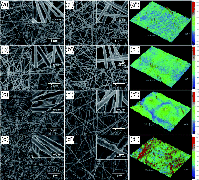 |
| | Fig. 3 (a–d) FE-SEM images of various hybrid fibrous membranes formed from composite PVA solutions containing different contents of added silica nanoparticles: (a) 0, (b) 0.79, (c) 1.58 and (d) 3.16 wt%. (a′–d′) FE-SEM images and (a′′–d′′) corresponding optical profilometry images of inorganic silica fibrous membranes containing various contents of silica nanoparticles: (a′, a′′) 0, (b′, b′′) 9.7, (c′, c′′) 19.4, and (d′, d′′) 38.8 wt%. | |
Table 1 Characteristics of solutions and resultant fibers
| Sample name |
Content of silica nanoparticles (wt%) |
Viscosity/cps |
Conductivity/μS m−1 |
Surface tension/mN m−1 |
Av. fiber diameter before calcination/nm |
Av. fiber diameter after calcination/nm |
BET surface area of silica membranes/m2 g−1 |
| PVA/TEOS |
— |
130 |
660 |
37.14 |
320 |
254 |
2.47 |
| 0.79 |
160 |
748 |
35.57 |
352 |
290 |
7.42 |
| 1.58 |
180 |
976 |
36.57 |
405 |
315 |
8.43 |
| 3.16 |
320 |
690 |
35.14 |
442 |
369 |
8.64 |
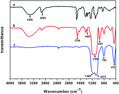
On adding silica nanoparticles in the composite solutions, the fibers formed from composite PVA solutions containing silica nanoparticles of 0.79 (Fig. 3b), 1.58 (Fig. 3c) and 3.16 wt% (Fig. 3d) all showed an increased average fiber diameter of 352, 405 and 442 nm as well as a bead-on-string structure similar to the hybrid PVA nanofibers without silica nanoparticles (Fig. 3a). The increase in fiber diameter can be attributed to the enhanced viscosity of the composite solutions after adding silica nanoparticles (Table 1). High-resolution FE-SEM images in Fig. 3b–d clearly show that the fibers exhibit a well-developed nanotextured rough structure on the fiber surface, which could be attributed to rapid phase separation in the electrospinning process and thus lead to silica nanoparticles protruding on the surfaces of the fibers.27,28Fig. 4 shows typical FTIR spectra of PVA, PVA/silica, and silica membranes. The absorption features of PVA were found at 3400 cm−1 (–OH), 2900 cm−1 (–CH2), 1740 cm−1 (C=O), 1450 cm−1 (O=C–OR), 1340 cm−1 (–CH2), and 1110 cm−1 (C–O–C), respectively (Fig. 4a).25,29Fig. 4b shows an FTIR spectrum of PVA/silica nanofibrous membranes. Besides some absorption features of PVA, absorption peaks at 1100, 790, and 470 cm−1 were observed in the case of the Si–O–Si bond and the peak around 929 cm−1 was assigned to the Si–OH bond, which indicates the existence of silica in the composite fibers.25,30
FE-SEM images of inorganic silica fibrous membranes containing various contents of silica nanoparticles are exhibited in Fig. 3a′–d′. After the calcination at 800 °C, the 3D porous fibrous membranes with bead-on-string structure were still maintained in these membranes. The average diameter of the silica fibers was decreased in all cases, due to the pyrolysis of PVA in the hybrid PVA/silica membranes. The complete pyrolysis of PVA in composite membranes was confirmed by the FT-IR result in Fig. 4c. All the peaks corresponding to PVA molecules disappeared; only the peaks around 1160, 1070, 790, and 470 cm−1 corresponding to the Si–O–Si bond were observed. Meanwhile, the Si–OH band at 929 cm−1 disappeared after the calcinations.25 As a result, the calcined sample was composed of silica only. It is worth noting that inorganic silica fibrous membranes loaded with 38.8 wt% silica nanoparticles showed a lotus-leaf-like structure with numerous nanoparticles protruding on the surfaces of fibers (Fig. 3d′, inset). This protuberant structure created enhanced surface roughness and additional surface area, which might significantly boost the superhydrophobic properties.
The rough surface of the inorganic silica fibrous membranes was also confirmed by the optical profilometry images (Fig. 3a′′–d′′) and the BET surface area results in Table 1. The average surface roughness, Ra, of silica fibrous membranes without silica nanoparticles was 2.00 μm and a surface profile obtained by interferometric optical profilometry is presented in Fig. 3a′′. The larger content of silica nanoparticles loaded in the silica fibers resulted in a rougher surface, with Ra values of 2.03, 3.32, and 4.39 μm for silica fibrous membranes containing 9.7, 19.4, and 38.8 wt% silica nanoparticles, respectively. Additionally, the results from BET surface area measurements also support these observations (Table 1). Compared with the low specific surface area (2.47 m2 g−1) of the smooth silica fibrous membranes without silica nanoparticles, silica fibrous membranes containing 38.8 wt% silica nanoparticles possess a highly enhanced specific surface area of 8.64 m2 g−1, indicating an increase of at least a factor of 3.5.
Flexibility of silica fibrous membranes
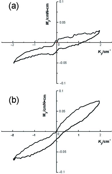
Fig. 5 shows an optical image of two flexible silica fibrous membranes when bent with a glass tube, indicating the flexibility of the nanofibrous silica membranes. We were pleased to find that the silica membranes were very flexible and no cracks appeared during the bending process. Several possible reasons may be responsible for the improved flexible properties. Firstly, the amorphous silica comprises an enormous network of corner-linked SiO4 tetrahedrons.31,32 Secondly, the resultant silica nanofiber is a one-dimensional (1D) system composed of minimal crystal grains and the boundary component among the crystal grains. The especially small size of the crystal grains results in an increased volume percentage of boundary component which means more atoms could be distributed on the boundary. Thus, the stress concentration is decreased substantially which reduces the chance of the generation and extension of micro-cracks on the fibers. Consequently, the extremely small size of the 1D silica nanofibers leads to the flexibility of the 3D silica membranes.25 Additionally, the flexibility of the membranes can also be characterized by bending rigidity.33 Usually, for a fabric, a lower bending rigidity means better flexibility. To determine the bending rigidity of the silica fiber membranes, a KES-FB2S test was conducted on silica fibrous membranes containing silica nanoparticles at 0 and 38.8 wt%. The dimension of the sample in the bending direction is equal to 1 cm and its width is 20 cm for flexible fabrics. It is clamped between fixed and moving clamps. The fixture setting of the sample in the clamps ensures pure bending deformation. During the test, the moving clamp rotates round the fixed one ensuring a constant curvature through the sample length. Fig. 6 presents the results of the KES-FB2S tests carried out on the two silica membranes. According to the manual of the device, the bending rigidity B of Grosberg's model are computed as follows.34
The slopes are computed respectively between κ = 0.5 cm−1 and κ = 1.5 cm−1 for s1 and between κ = −0.5 cm−1 and κ = −1.5 cm−1 for s2:
| |  | (1) |
| |  | (2) |
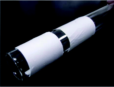 |
| | Fig. 5 Optical image of flexible silica fibrous mats when bent with a glass tube. | |
Combining Fig. 6 and eqn (1–3), we can obtain the B values of the silica membranes. For the silica fibrous membranes containing silica nanoparticles at 0 and 38.8 wt% B was 0.0095 and 0.0279 gf cm, respectively, thereby implying their comparable flexibility. Increasing the silica nanoparticles in the membranes enhanced the B values of the silica membranes as well as decreasing their flexibility. To this end, this work has demonstrated that relatively flexible surfaces having a lotus leaf-like wetting characteristic can be fabricated by electrospinning from economically available PVA in combination with silica nanoparticles without the requirement for microstructured templates.
Wettability of fluorinated silica fibrous membranes
The wettability of fluorinated silica fibrous membranes was studied by measuring the contact angles of water, oil, milk and orange juice on the nanofiber film. As can be seen from Fig. 7, the silica membrane is strongly non-wettable for all of the liquid droplets evaluated. Fig. 8a shows the WCA measurements of the silica fibrous membranes loaded with increasing silica nanoparticle content from 0 to 38.8 wt%. Selected water droplet images and an optical image of the water droplet seated on a fluorinated silica fibrous membrane containing 38.8 wt% silica nanoparticles are shown in the insets. The fluorinated silica samples loaded with 0 and 9.7 wt% silica nanoparticles did not show superhydrophobicity (WCAs of 140° and 148°, respectively). The fluorinated silica fibrous membranes loaded with 19.4 wt% silica nanoparticles presented superhydrophobicity with a WCA of 150°, which could be attributed to the low surface energy of FAS and the increased surface roughness due to the nanometre-scale papillae on the fiber surfaces (Fig. 3c′). Further increasing the content of silica nanoparticles (38.8 wt%) resulted in a rougher surface with numerous papillae, which achieved a stable superhydrophobic state with a WCA of 155°. As the tilt angle of a superhydrophobic surface indicates the water–solid interface energy that immobilizes a water droplet, the self-cleaning ability of a surface can also be effectively characterized by the threshold sliding angle.34 We determined the sliding angles of water droplets on fluorinated silica fibrous membranes by placing a 10 mg drop of water on the textured fibrous surface, which was then inclined at increasing angles until the drop started to roll. As the silica nanoparticle content increased on our micro-textured surfaces, we observed a concurrent decrease in sliding angle. The fluorinated silica fibrous membranes with a silica nanoparticle content of 38.8 wt% showed the lowest tilt angle of 3°.
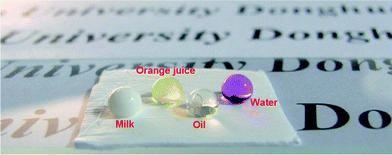 |
| | Fig. 7 Droplets of water, oil, milk, and orange juice on a fluorinated silica sample containing 38.8 wt% silica nanoparticles. | |
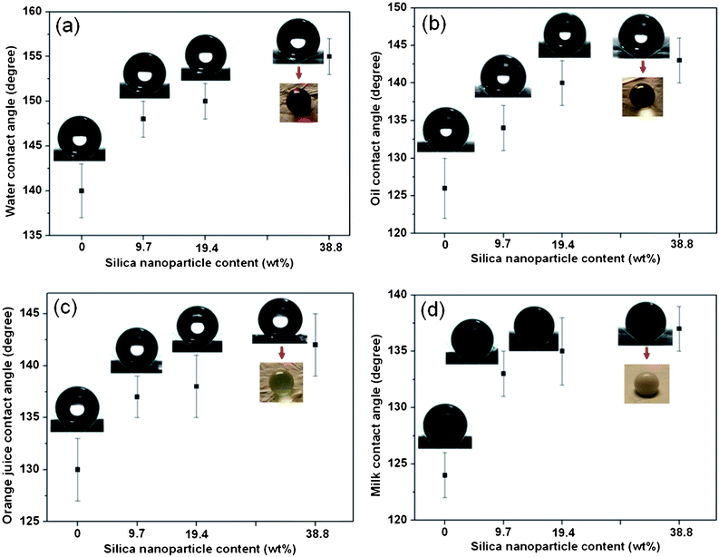 |
| | Fig. 8 Various liquid contact angles and the corresponding shapes of droplets for the fluorinated silica samples with increasing silica nanoparticle content from 0 to 38.8 wt%: (a) water, (b) oil, (c) orange juice, (d) milk. The inset optical images show the liquid droplets seated on the fluorinated silica fibrous membranes with a silica nanoparticle content of 38.8 wt%. | |
Hydrophobic surface roughness will prevent the water droplet from contacting the solid surface completely by trapping air bubbles at the liquid–solid interface. The WCA of air is commonly regarded as 180°. Cassie and Baxter proposed eqn (4) to describe the relationship between the contact angle on a flat surface (θ) and a rough surface (θr) composed of a solid and air.2
In this equation, f1 and f2 are the ratios of the solid surface and air in contact with the liquid, respectively. In other words, f1 + f2 = 1. This equation predicts that increasing the fraction of air (f2) would increase the contact angle of the nanofibrous membranes (θr). Given the WCAs of the fluorinated flat silica films and rough silica fibrous membranes,25 the f2 value of the rough surface was calculated to be 0.75, which indicated that the enhancement of superhydrophobicity by fluorinated nanofibrous silica membranes was a result of the air trapped in the rough hierarchical micro/nanostructures of the membranes.
We also examined OCAs (Fig. 8b), OJCAs (Fig. 8c) and MCAs (Fig. 8d) of the fluorinated silica fibrous membranes loaded with various contents of silica nanoparticles. Similar to the WCAs of the fluorinated silica fibrous membranes, the CAs of these three liquids all increased with increased silica nanoparticle content from 0 to 38.8 wt%. The average OCA, OJCA and MCA for fluorinated silica fibrous membranes loaded with 38.8 wt% silica nanoparticles were 143°, 142° and, 137° respectively. The remarkable performance of the novel fluorinated silica fibrous membranes is a result of the synergy between an increase of the nanoscale surface roughness imparted by the silica nanoparticles and a significant reduction of the surface free energy due to the presence of a high concentration of FAS molecules on the fiber surface.
Conclusions
In summary, we have successfully prepared flexible silica nanofibrous membranes with biomimetic non-wettable surfaces through electrospinning, calcination, and surface modification techniques. The content of silica nanoparticles incorporated into the fibers proved to be the key factor affecting the fiber surface morphology and wettability. The resultant nanoparticle decorated silica fibrous membranes with lotus-leaf-like structure showed a highest WCA of 155°, OCA of 143°, OJCA of 142°, and MCA of 137°. Moreover, the fluorinated silica membranes exhibited good flexibility. The bending rigidity values B for the silica fibrous membranes containing silica nanoparticles at 0 and 38.8 wt% were 0.0095 and 0.0279 gf cm, respectively, thereby implying their comparable flexibility. This simple, large area, and low-cost fabrication method of superhydrophobic inorganic fibrous membranes makes them suitable as flexible self-cleaning surfaces for several application fields including high-temperature filtration, novel easy-clean coatings, and waterproof textiles.
Acknowledgements
This work is supported by the National Natural Science Foundation of China (No. 50803009 and 51173022), the “111 Project” (No. 111-2-04 and B07024), the Shanghai Committee of Science and Technology (No. 10JC1400600), the National Basic Research Program of China (973 Program, 2011CB606103), the Innovation Program of Shanghai Municipal Education Commission (11ZZ59), and the “Dawn” Program of Shanghai Education Commission (10SG32).
References
- F. Xia and L. Jiang, Adv. Mater., 2008, 20, 2842–2858 CrossRef CAS.
- L. Jiang, Y. Zhao and J. Zhai, Angew. Chem., Int. Ed., 2004, 43, 4338–4341 CrossRef CAS.
- J. Y. Lin, Y. Cai, X. F. Wang, B. Ding, J. Y. Yu and M. R. Wang, Nanoscale, 2011, 3, 1258–1262 RSC.
- X. F. Gao and L. Jiang, Nature, 2004, 432, 36–36 CrossRef CAS.
- L. Feng, S. H. Li, Y. S. Li, H. J. Li, L. J. Zhang, J. Zhai, Y. L. Song, B. Q. Liu, L. Jiang and D. B. Zhu, Adv. Mater., 2002, 14, 1857–1860 CrossRef CAS.
- X. Yao, Y. Song and L. Jiang, Adv. Mater., 2011, 23, 719–734 CrossRef CAS.
- Z. Guo, W. Liu and B.-L. Su, J. Colloid Interface Sci., 2011, 353, 335–355 CrossRef CAS.
- Z. Z. Gu, H. Uetsuka, K. Takahashi, R. Nakajima, H. Onishi, A. Fujishima and O. Sato, Angew. Chem., Int. Ed., 2003, 42, 894–896 CrossRef CAS.
- K. Liu, X. Yao and L. Jiang, Chem. Soc. Rev., 2010, 39, 3240 RSC.
- P. Roach, N. J. Shirtcliffe and M. I. Newton, Soft Matter, 2008, 4, 224 RSC.
- B. Bhushan and Y. C. Jung, Prog. Mater. Sci., 2011, 56, 1–108 CrossRef CAS.
- K. S. Liu and L. Jiang, Nanoscale, 2011, 3, 825–838 RSC.
- M. Ma, R. M. Hill and G. C. Rutledge, J. Adhes. Sci. Technol., 2008, 22, 1799–1817 CrossRef CAS.
- Y. J. Xiao, H. Q. Cao, K. Y. Liu, S. C. Zhang and V. Chernow, Nanotechnology, 2010, 21, 145601 CrossRef.
- B. Ding, M. R. Wang, X. F. Wang, J. Y. Yu and G. Sun, Mater. Today, 2010, 13, 16–27 CrossRef CAS.
- B. Ding, X. Wang, J. Yu and M. Wang, J. Mater. Chem., 2011, 21, 12784–12792 RSC.
- R. Nirmala, R. Navamathavan, H. S. Kang, M. H. El-Newehy and H. Y. Kim, Colloids Surf., B, 2011, 83, 173–178 CrossRef CAS.
- X. Wang, B. Ding, J. Yu, M. Wang and F. Pan, Nanotechnology, 2010, 21, 055502 CrossRef.
- H. Yoon, J. H. Park and G. H. Kim, Macromol. Rapid Commun., 2010, 31, 1435–1439 CrossRef CAS.
- M. Ma, M. Gupta, Z. Li, L. Zhai, K. K. Gleason, R. E. Cohen, M. F. Rubner and G. C. Rutledge, Adv. Mater., 2007, 19, 255–259 CrossRef CAS.
- B. Ding, T. Ogawa, J. Kim, K. Fujimoto and S. Shiratori, Thin Solid Films, 2008, 516, 2495–2501 CrossRef CAS.
- M. Kanehata, B. Ding and S. Shiratori, Nanotechnology, 2007, 18, 315602 CrossRef.
- H. Z. Tang, H. Wang and J. H. He, J. Phys. Chem. C, 2009, 113, 14220–14224 CAS.
- Y. Zhu, J. C. Zhang, J. Zhai, Y. M. Zheng, L. Feng and L. Jiang, ChemPhysChem, 2006, 7, 336–341 CrossRef CAS.
- M. Guo, B. Ding, X. H. Li, X. L. Wang, J. Y. Yu and M. R. Wang, J. Phys. Chem. C, 2010, 114, 916–921 CAS.
- H. Fong, I. Chun and D. H. Reneker, Polymer, 1999, 40, 4585–4592 CrossRef CAS.
- Y. Miyauchi, B. Ding and S. Shiratori, Nanotechnology, 2006, 17, 5151–5156 CrossRef CAS.
- J. Y. Lin, B. Ding, J. Y. Yu and Y. Hsieh, ACS Appl. Mater. Interfaces, 2010, 2, 521–528 CAS.
- B. Ding, E. Kimura, T. Sato, S. Fujita and S. Shiratori, Polymer, 2004, 45, 1895–1902 CrossRef CAS.
- T. Nakagawa and M. Soga, J. Non-Cryst. Solids, 1999, 260, 167–174 CrossRef CAS.
- C. L. Shao, H. Kim, J. Gong and D. Lee, Nanotechnology, 2002, 13, 635–637 CrossRef CAS.
- A. M. Walker, L. A. Sullivan, K. Trachenko, R. P. Bruin, T. O. H. White, M. T. Dove, R. P. Tyer, I. T. Todorov and S. A. Wells, J. Phys. -Condens. Matter, 2007, 19, 275210 CrossRef.
- E. Bilbao, D. Soulat, G. Hivet and A. Gasser, Exp. Mech., 2010, 50, 333–351 CrossRef.
- K. Acatay, E. Simsek, C. Ow-Yang and Y. Z. Menceloglu, Angew. Chem., Int. Ed., 2004, 43, 5210–5213 CrossRef CAS.
- W. Barthlott and C. Neinhuis, Planta, 1997, 202, 1–8 CrossRef CAS.
Footnote |
| † These authors contributed equally to this work. |
|
| This journal is © The Royal Society of Chemistry 2011 |
Click here to see how this site uses Cookies. View our privacy policy here. 
![[thin space (1/6-em)]](https://www.rsc.org/images/entities/char_2009.gif) 000, Aladdin Chemical Co., China), tetraethyl orthosilicate (TEOS, Lingfeng Chemical Co., Ltd., China), phosphoric acid (85 wt%), silica nanoparticles (diameter of particles, 7–40 nm; specific surface area, 120 m2 g−1; Aladdin), fluoroalkylsilane (FAS, Gelest Inc., USA), hexane (Sinopharm Chemical Reagent Co., Ltd., China), oil (Arowana Salad Oil), milk (Yili Pure Milk), orange juice (Orange Unified), and pure water.
000, Aladdin Chemical Co., China), tetraethyl orthosilicate (TEOS, Lingfeng Chemical Co., Ltd., China), phosphoric acid (85 wt%), silica nanoparticles (diameter of particles, 7–40 nm; specific surface area, 120 m2 g−1; Aladdin), fluoroalkylsilane (FAS, Gelest Inc., USA), hexane (Sinopharm Chemical Reagent Co., Ltd., China), oil (Arowana Salad Oil), milk (Yili Pure Milk), orange juice (Orange Unified), and pure water.
![[thin space (1/6-em)]](https://www.rsc.org/images/entities/char_2009.gif) :
:![[thin space (1/6-em)]](https://www.rsc.org/images/entities/char_2009.gif) H3PO4
H3PO4![[thin space (1/6-em)]](https://www.rsc.org/images/entities/char_2009.gif) :
:![[thin space (1/6-em)]](https://www.rsc.org/images/entities/char_2009.gif) H2O = 1
H2O = 1![[thin space (1/6-em)]](https://www.rsc.org/images/entities/char_2009.gif) :
:![[thin space (1/6-em)]](https://www.rsc.org/images/entities/char_2009.gif) 0.01
0.01![[thin space (1/6-em)]](https://www.rsc.org/images/entities/char_2009.gif) :
:![[thin space (1/6-em)]](https://www.rsc.org/images/entities/char_2009.gif) 11 was prepared by hydrolysis and polycondensation by dropwise addition of H3PO4 to TEOS with stirring at room temperature for 6 h. Then 10 g silica gel was dropped slowly into 10 g PVA solutions and stirred for another 6 h. Then 0, 0.16, 0.32 and 0.64 g silica nanoparticles were added into the PVA/silica gel solutions, respectively. Thus, viscous composite solutions containing different contents of added silica nanoparticles (0, 0.79, 1.58 and 3.16%), used as the electrospinning solutions, were obtained.
11 was prepared by hydrolysis and polycondensation by dropwise addition of H3PO4 to TEOS with stirring at room temperature for 6 h. Then 10 g silica gel was dropped slowly into 10 g PVA solutions and stirred for another 6 h. Then 0, 0.16, 0.32 and 0.64 g silica nanoparticles were added into the PVA/silica gel solutions, respectively. Thus, viscous composite solutions containing different contents of added silica nanoparticles (0, 0.79, 1.58 and 3.16%), used as the electrospinning solutions, were obtained.


