Novel nanofibrous composite of chitosan–CaCO3 fabricated by electrolytic biomineralization and its cell biocompatibility
Wei
Zhang
a,
Ting
Liu
a,
Xianluo
Hu
b and
Jingming
Gong
*a
aKey Laboratory of Pesticide & Chemical Biology of Ministry of Education, College of Chemistry, Central China Normal University, Wuhan, 430079, P. R. China. E-mail: jmgong@mail.ccnu.edu.cn; Tel: +86-27-6786 7535.
bState Key Laboratory of Material Processing and Die & Mould Technology, College of Materials Science and Engineering, Huazhong University of Science and Technology, Wuhan, 430074, P. R. China
First published on 16th November 2011
Abstract
A nanofibrous network-like CaCO3–chi (CaCO3–chi NFs) composite has been successfully fabricated in a simple and controllable approach based on one-step electrodeposition. Results confirm that chitosan can behave as a structure-directing agent during the formation of the CaCO3–chi composite coating, playing an important role. The as-formed CaCO3–chi NFs were observed to be covered by multiple small nanoparticles (NPs) with an average diameter of ∼25 nm. These uniform NPs were aligned along the surface of NFs, constructing a 3D hierarchically interlaced network. Cytocompatibility of these NFs was evaluated by cell morphology and a MTT assay by culturing MC3T3 cells. The results show that the composite coating of CaCO3–chi NFs featuring interconnected pores, loose 3D assembly, large surface area, and high mechanical strength, possess excellent cytocompatibility, greatly facilitating cell adhesion and proliferation. Our research demonstrates that the composite of CaCO3–chi NFs can be fabricated in an easy manner, i.e. electrolysis induced biomineralization, and act as a promising scaffold for tissue engineering applications.
1. Introduction
Recent advances in inorganic–organic hybrid nanomaterials are of growing interest because of their intriguing properties and potential applications in sensing, catalysis, environmental cleanup, nanodevices and tissue engineering.1–7 The hybrid composite, without compromising the functions of the organic matrix or inorganic compounds, shows significant improvements in mechanical properties and biocompatibility over the organic or inorganic compounds alone.3 Several methods have been developed for the preparation of the hybrid inorganic–organic nanomaterials, including hot press molding, plasma spraying, in situpolymerization, biomorphic template, and self-organized assembly.8–12 Among these approaches, bottom-up biomineralization for the preparation of calcite micro and nanostructures has aroused enormous interest from scientists worldwide.13–23 These calcite skeletons are not just limited to their eye-catching appearance, but find significant potential in biosensing, mineralisation, medical, nanodevices and pharmaceutical applications.24–26 Such a bio-inspired approach has afforded more complicated biomineral structures, such as helix-like inorganic minerals induced by a racemic block copolymer,27 hierarchical self-similar calcite mesocrystals,28 network-like chitosan-hydroxyapatite induced by biomimetic mineralization,29 single crystal calcite grown in agarose hydrogels,30 and controlled nucleation and growth of hydroxyapatite (HAP) crystals on electrospun fibers.31 Despite these outstanding achievements, the fabrication of minerals of higher morphological complexity in a simple and controllable fashion still remains a significant challenge.Currently, electrochemical deposition methods are becoming increasingly popular, owing to ease of process control, variability of coating composition, and suitability for complex implant geometries.32–35 The conception of electrolysis induced biomineralization has been already proposed.36 Recently, we developed a facile one-step electrodeposition approach for the construction of nanowall arrays of CaCO3-chitosan (CaCO3–chi NW) composite coating.37 It was found that the presence of an appropriate amount of chitosan is essential for the formation of nanowall arrays. In this work, with further introducing the excess amount of chitosan into the electrolyte, interestingly, three dimensional (3D) nanofibrous composite of CaCO3-chitosan (labeled as CaCO3–chi NFs) were formed via the proposed electrodeposition approach. Owing to the extraordinary characteristics (e.g., tunable porosity, malleability, and high surface area), 3D fibrous composite have aroused considerable interest to a broad range of disciplines including materials chemistry, sensor and biomedical-related fields.31,38–41 The as-prepared 3D composite of CaCO3–chi NFs featuring interconnected pores, loose 3D assembly, high surface area, and resembling the topographic features of extracellular matrix, are expected to have potential applications for tissue engineering.
3D fibrous scaffolds of hydroxyapatite-polymer have previously been used for cell tissue engineering viaelectrospinning or electrospinning combined with precipitation strategy.31,42 However, electrospinning only allows fabrication of nanofibers under high-voltage conditions (15∼50 kV). The nanofibers prepared are all amorphous with only thread-like morphology. In addition, normally a cross-linker, such as glutaraldehyde (GTA), a substance that is toxic during the biodegradation process, has to be used, which to a certain extent limits its applications. The biocompatibility of the as-prepared scaffold of CaCO3–chi NFs as well as NWs were assessed by culturing MC3T3-E1 mouse osteoblast cells, which is commonly used to assess cytotoxicity of potential substrates for cell growth. Encouragingly, our work not only demonstrates that CaCO3–chi NFs can be fabricated in an easy and controllable manner, but also presents the impact of CaCO3–chi surface nanostructure on the adhesion and proliferation of MC3T3-E1 cells.
2. Experimental section
2.1. Materials
Chitosan from crab shells (85% deacetylated) was purchased from Sigma. MC3T3-E1 osteoblast-like cells were obtained from Boster Company. Dulbecco's Modified Eagles Medium (DMEM, high Glucose), fetal bovine serum (FBS), 3-(4,5-dimethylthiazol-2-yl)-2,5-diphenyl- tetrazolium bromide (MTT) and phosphate buffer saline solution (PBS, pH 7.4) were purchased from Hyclon, respectively. Glutaraldehyde and dimethylsulfoxide (DMSO) were obtained from Sinopharm Chemical Reagent Co., Ltd. 4′, 6-diamidino-2-phenylindole (DAPI) was used from Biosharp. All other chemicals were of analytical-reagent grade and used without further purification. Stainless steel foils (0.8 cm × 2 cm × 0.075 cm, A1SI 304) as substrates for deposition were purchased from Good-follow Cambridge Ltd. Deionized water (18.2 MΩ resistances) was used throughout. All experiments were carried out at ambient temperature.2.2. Instruments
The general morphology of the products was characterized by scanning electron microscopy (SEM, JSM-5600). Electron diffraction patterns were obtained by TEM (Philips CM 120, 120 kV). XRD patterns were collected with a Rigaku D/MAX-RB diffractometer with high-intensity Cu Kα1 irradiation (λ = 1.5406 Å). Fluorescent microscopy was recorded on a fluorescent microscope (LEICA DMI3000B, Feica) equipped with a CCD camera (Model DP71). Electrochemical preparations were performed on a CHI 660D electrochemical workstation (CHI, USA) with a conventional three-electrode system comprising a platinum wire as the auxiliary electrode, a saturated calomel electrode (SCE) as the reference and the stainless steel foil (SS, 0.8 cm × 2 cm) as the working electrode. Mechanical testing was performed on a computer-controlled MTS 810 (MTS Co., USA). The test process involves first fixing the test specimen (100.0 × 10.0 × 0.75 mm3) and then applying tension to it until it fractures. Five separate runs were performed for each sample.2.3. Preparation of CaCO3–chi NFs onto a SS substrate
The bare SS foils were sonicated in ethanol and doubly distilled water for 5 min, successively, in order to remove any adsorbed substance on the substrate surface. Then, it was dried under nitrogen atmosphere ready for use. Chitosan solution was prepared by mixing chitosan flakes with water followed by adjusting the pH value to ∼5 by HCl solution. The undissolved part was removed by a 0.45 μm syringe filter unit. The final concentration of chitosan solution was estimated to be 0.45 mg mL−1. The electrolyte was then obtained by dissolving CaCl2 (4.5 mM) and NH4HCO3 (9 mM) into the as-prepared chitosan solution under strongly stirring for ∼0.5 h. Then the pH value of the electrolyte was re-adjusted to 5.5. Subsequently, the cleaned SS was immersed into the electrolyte at a constant potential of −3.0 V vs.SCE for 30 min. While the pH shift-induced deposition of chitosan was synchronized with the precipitation of CaCO3 minerals onto GCE, a composite film of CaCO3–chi nanofibers was formed (labeled as CaCO3–chi NFs/SS). For comparison, CaCO3–chi nanowall arrays (CaCO3–chi NWs/SS) were also synthesized according to our previous report.372.4. Cell culture and seeding
Cell studies were conducted using clonal MC3T3-E1 cells. The cells were cultured in DMEM medium supplemented with 10% (v/v) fetal bovine serum, 100 units/μL penicillin, and 100 mg μL−1streptomycin at 37 °C, 5% CO2. The culture medium was refreshed every 2 days. Cells were detached from the culture plate at 80–85% confluence and used for the following seeding on the various scaffolds. Prior to cell seeding, CaCO3–chi/SS scaffolds were cut into square samples with 0.8 cm × 0.8 cm. Subsequently, all the samples were sterilized by immersing them in 75% ethanol for 30 min, exposing them to UV radiation for 2 h on each side, and then washing each three times in a sterile PBS, pH 7.4. These samples were placed individually into the 24-well plate and seeded with the cell suspension as ∼1 × 10⁵cells mL−1 of medium. The cell-seeded scaffolds were kept at 37 °C in the CO2 incubator, cultured for either a few hours or days according to the different regimes.2.5. Evaluation of cell adhesion and morphology
The morphologies of cells grown on various scaffolds (bare SS, CaCO3–chi NWs/SS or CaCO3–chi NFs/SS) were observed by SEM. After 3 days of culturing, the cell-seeded square samples were removed from the culture and gently washed with PBS. The cells on the square samples were immobilized with 2.5% glutaraldehyde in PBS for 1 h at 4 °C. After removing the fixative, the square samples were subsequently gently washed in PBS and distilled water. These samples were subjected to sequential dehydration through a series of graded ethanol solutions (10, 30, 50, 70, 85, 90, 95, and 100%) . Further, samples were allowed to dry for a day, coated with platinum for 40 s, and examined with SEM for cell adhesion and morphology.2.6. Fluorescence microscopy
A fluorescent microscope equipped with a CCD camera was further used to examine cell morphology and cytoskeletal arrangement in osteoblasts seeded onto various scaffolds surfaces. After different culturing time, cells were fixed with 4% paraformaldehyde in 0.1 M PBS, pH 7.4, at 4 °C for 30 min. Then the square samples were washed with PBS and stained using the fluorescent dye DAPI (Biosharp). Subsequently, the stained scaffolds were kept at 37 °C in the CO2 incubator. After 2 h, the adherent cells were washed once with PBS and fluorescence images were captured using a fluorescent microscope equipped with a CCD camera. The fluorescence signal was recorded using band-pass excitation filter (330–385 nm), high pass emission filter (420 nm) and 400 nm dichromatic mirrors.2.7. Cell proliferation and cytocompatability of the scaffolds
The initial cell attachment and proliferation on each scaffold are evaluated with a MTT assay. For the assay, cells were seeded on CaCO3–chi square scaffolds in 24 well plates at a density of 104cells mL−1 and were incubated under the standard culturing conditions. After incubation for 1, 3, 5, 7 and 9 days, the square scaffolds were transferred to another 24-well plate filled with 800 μL of fresh DMEM with 10% FBS in each well. After incubating at 37 °C for 1 h, 80 μL MTT reagent was added into each well and incubated for 4 h according to the reagent instructions. After the formed formazan solution (100 μL) was taken from each sample and transferred to one well of a 96-well plate, the adsorbance at 490 nm was determined using a microplate reader (Elx-800, Bio-Tek instrument Inc., Winooski, VT). Six parallel replicates (n = 6) for each sample were used to assess cell proliferation.2.8. Statistical analysis
The statistical analysis of all the experimental data was performed using SPSS version 11.0. Data was expressed as the mean ± standard deviation. Statistical comparisons were performed by ANOVA for multiple comparisons, and statistical significance was accepted at p < 0.05.3. Results and discussion
3.1. Characterization of CaCO3–chi NFs on a cathodic substrate
Fig. 1 shows the typical SEM and TEM images of the as-prepared CaCO3–chi composite film deposited on a SS substrate at E = −3V versusAg/AgCl. Seen from Fig. 1a, it clearly indicates that the product consists of nanofiber structures. It can be seen that the as-prepared NFs have diameters of ∼40 nm and lengths up to several tens of micrometres. These NFs interlaced together and formed fiber network structures. As shown in a high-magnification SEM image (inset of Fig. 1a), clearly, the NFs consist of the aggregation of multiple small nanoparticles (NPs). These uniform nanoparticles were aligned along the surface of those NFs, constructing a 3D hierarchically interlaced network. Fig. 1b displays the TEM image of some representative nanofiber fragments. One can see that the surface of the fiber was covered by multiple NPs with an average diameter of ∼25 nm, showing consistency with the results of SEM.![(a) Low-magnification and enlarged SEM images (inset) of nanofibrous CaCO3–chi composite deposited onto a SS substrate by one-step electrodeposition at E = −3 V vs.Ag/AgCl for 30 min. Electrolyte: [Ca2+] = 4.5 mM, [HCO3−] = 9 mM and 0.45 mg mL−1 chitosan, initial pH = 5.5. (b) TEM image of typical nanofiber structures.](/image/article/2012/RA/c1ra00549a/c1ra00549a-f1.gif) | ||
| Fig. 1 (a) Low-magnification and enlarged SEM images (inset) of nanofibrous CaCO3–chi composite deposited onto a SS substrate by one-step electrodeposition at E = −3 V vs.Ag/AgCl for 30 min. Electrolyte: [Ca2+] = 4.5 mM, [HCO3−] = 9 mM and 0.45 mg mL−1 chitosan, initial pH = 5.5. (b) TEM image of typical nanofiber structures. | ||
The crystallinity of the resulting nanofibers was further confirmed by XRD analysis. The characteristic reflection at 2θ = 23.2, 29.6, 36.0, 39.6, 47.6, and 48.8°, corresponds to the hexagonal crystal structure of CaCO3 (JCPDS no.81-2027), indicating the formation of calcite (Fig. 2) onto the substrate.
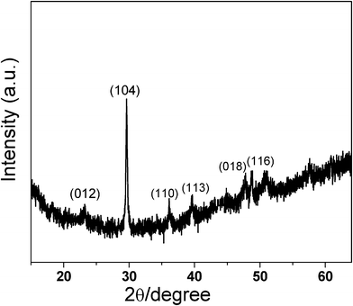 | ||
| Fig. 2 XRD pattern of the as-prepared composite film of CaCO3–chi nanofibrous composite deposited onto a SS substrate. | ||
XPS measurements were made to further confirm the composition of nanofibers. The peak appearing at 347.4, and 350.9 eV corresponds to Ca 2p3/2 and Ca 2p1/2, indicating the presence of Ca2+. The N 1s peak at 398.8 eV and the C 1s peak at 284.6 eV can be attributed to the incorporated chitosan in the composite film (shown in Fig. 3). Obviously, the composite film is the product of the incorporation of chitosan and CaCO3. It can be shown that 3D nanofibrous network structure of CaCO3–chi composite coating on a SS substrate could be successfully fabricated through a facile one-step electrodeposition approach. In our previous work, the influence of chitosan amounts on the morphology of CaCO3–chi composite coating has been studied in detail.37 It was demonstrated that the presence of an appropriate amount of chitosan is essential for the formation of well-aligned CaCO3–chi nanowall arrays via the proposed electrodeposition process.37 In this work, by introducing an excess amount of chitosan into the electrolyte, a nanofibrous composite of CaCO3–chi is synthesized, further confirming that chitosan acts as a structure-directing agent during the formation of CaCO3–chi composite coating.
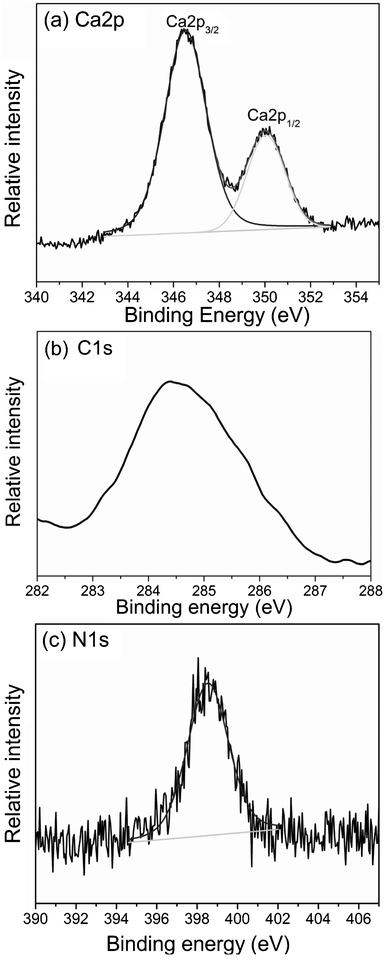 | ||
| Fig. 3 XPS spectra of (a) Ca2p, (b) C1s and (c) N1s of the as-prepared composite film of CaCO3–chi nanofibers deposited onto a SS substrate. | ||
The mechanical properties of the as-prepared fibers were detected. It was noted that the obtained fibrous CaCO3–chi composite had significantly higher tensile strength (1317.2 ± 4.6 MPa) than that of the bare SS (738.1 ± 7.9 MPa), showing 78.5% reinforcement effect. Apparently, the presence of the nanofibrous CaCO3–chi coating improves the strength of the framework.
It is envisioned that the as-formed CaCO3–chi NFs, featuring interconnected pores, loose 3D assemble, large surface area, high mechanical strength, and resembling the topographic features of extracellular matrix, are expected to have potential applications for tissue engineering.
3.2. Cell adhesion and morphology
SEM was used to study the attachment and spreading of MC3T3 cells on the various scaffolds. As shown in Fig. 4, the morphology of MC3T3 cells exhibits a notable change after culturing for 3 days on the different surface of CaCO3–chi composite. On the surface of the CaCO3–chi NFs, MC3T3 cells were found flat lying onto the substrate, spreading with large area and tightly adhering to the surface of the reticular fibrous network. Moreover, many more pronounced protrusions of pseudopodia contact with the surface of reticular fibers of CaCO3–chi nanostructures (inset of Fig. 4a), prompting the adhesion of cells. Similar behavior was reported by RDK Misra on MC3T3 cells cultured on a chitosan scaffold.29 As is well known, biomaterial surfaces and their nanostructures can significantly influence cell growth and viability. To make a comparison, the attachment of MC3T3 cells on CaCO3–chi NWs scaffold was also observed. One can see that the cells exhibit a round morphology and become thicker (Fig. 4b), displaying a weaker adhesion ability to the surface of CaCO3–chi NWs scaffold. The above results suggest that on one hand, the morphology of MC3T3 cells could be affected by the surface morphology of the scaffolds; on the other hand, 3D interlaced fibrous network structures of CaCO3–chi NFs could behave as an excellent scaffold for cell adhesion and attachment.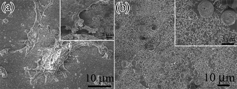 | ||
| Fig. 4 Typical SEM images of MC3T3 cells cultured on (a) CaCO3–chi NFs/SS scaffold, and (b) CaCO3–chi NWs/SS scaffold, respectively. Inset corresponds to the respective magnified SEM images of (a) and (b). | ||
3.3. Cytocompatability studies
MTT tests were carried out to observe the growth and proliferation of MC3T3-E1 cells on different scaffolds (such as SS, CaCO3–chi NWs/SS and CaCO3–chi NFs/SS scaffold), respectively. As was shown in Fig. 5, MC3T3 cells proliferate well and the number of the cells increased with the culture time on all scaffolds, indicating that all tested scaffolds were nontoxic. Importantly, MC3T3 cells indeed display the highest proliferation on CaCO3–chi NFs/SS, compared with the bare SS and CaCO3–chi NWs/SS. Furthermore, this difference is more and more obvious with the time extension of cell culture.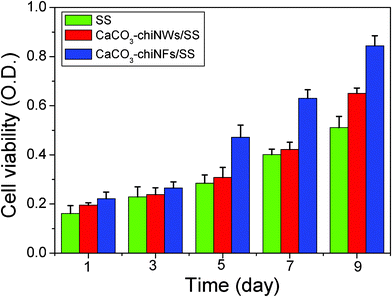 | ||
| Fig. 5 MTT assay formazan absorbance expressed as a measure of the cell viability of MC3T3 cells cultured on the bare SS, CaCO3–chi NWs/SS and CaCO3–chi NFs/SS scaffolds for different times. | ||
Fluorescent microscopy was further used to examine the cell cytoskeleton arrangement in MC3T3 seeded onto various scaffolds surfaces, as shown in Fig. 6. In fluorescence images, the bright green dots representing the nuclei clearly display a uniform and extensive distribution of MC3T3 cells on CaCO3–chi NFs/SS and CaCO3–chi NWs/SS scaffolds surface, respectively. Cell densities found in the images were consistent with the cell numbers. From the fluorescent images, one can see that the cell count at a certain proliferation stage was in the order of CaCO3–chi NFs/SS > CaCO3–chi NWs/SS, respectively, exhibiting higher proliferation rates on CaCO3–chi NFs/SS. And this difference is more and more obvious with prolonging the culture time, which is consistent with the MTT results. It further confirms a potential advantage of the fibrous CaCO3–chi NF scaffolds for tissue engineering.
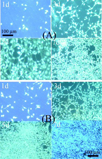 | ||
| Fig. 6 DAPI fluorescence staining of MC3T3 cells cultured on (A) CaCO3–chi NWs/SS, and (B) CaCO3–chi NFs/SS, the scale bar = 100 μm for all the images of (A) and (B). | ||
From the above experimental results, it is becoming clear that the synthetically nanofabricated topography and the scaffold composition can strongly influence the cell adhesion, attachment, and proliferation. Compared with the bare SS, whether CaCO3–chi NWs/SS or CaCO3–chi NFs/SS scaffold exhibits a promotion effect for cell proliferation. It was reported that cells adhere preferentially to and proliferate in regions with highly nanotextured nanofiber-based scaffolds.29,43 Herein, the interlaced nanofibrous composite of CaCO3–chi NFs/SS indeed exhibits a more favored tendency toward the cell attachment, spreading and proliferation, relative to the NW array structure. Besides, the hydrophilicity of the various scaffolds was also observed. As shown in Fig. 7, contact angle of the various scaffold was decreased in the order of 93 ± 7.0° (SS), 64.3 ± 7.0° (CaCO3–chi NWs/SS) and 32.4 ± 4.6° (CaCO3–chi NFs/SS). The scaffold with the lower contact angle, and the higher surface energy, could provide more active sites to facilitate the attachment and growth of cells. Literature has already reported that the increase of the hydrophilicity of scaffolds could enhance cell adhesion and proliferation as well.44–46 Evidently, the as-prepared CaCO3–chi NFs/SS scaffold favored cell adhesion, spreading, and growth.
 | ||
| Fig. 7 Contact angle images of MC3T3 cells on (a) bare SS, (b) CaCO3–chi NWs/SS, and (c) CaCO3–chi NFs/SS. | ||
4. Conclusions
In summary, a nanofibrous network-like CaCO3–chi composite has been successfully fabricated in a simple and controllable approach based on one-step electrodeposition. Such a three-dimensional CaCO3–chi nanofibrous network exhibits high cytocompatability by culturing MC3T3 cells, significantly enhancing cell adhesion and proliferation. Our research demonstrates that the scaffold of CaCO3–chi NFs can be fabricated in an easy manner, and behave as promising candidates for tissue engineering. We believe that the electrolysis induced biomineralization approach could be expanded to construct more novel nanostructured inorganic–organic hybrid materials and holds great promise for routine sensing and tissue engineering applications.Acknowledgements
This work was supported by the National Science Foundation of China (Grant 20803026, 21175053), Self-determined Research Funds of CCNU from the Colleges'Basic Research and Operation of MOE (Grant CCNU10A01006), and Program for Innovation Team of Hubei Province (2009CDA048).References
- A. L. Briseno, S. C. B. Mannsfeld, E. Formo, Y. J. Xiong, X. M. Lu, Z. N. Bao, S. A. Jenekhe and Y. N. Xia, J. Mater. Chem., 2008, 18, 5395–5398 RSC.
- T. Yoshida, J. Zhang, D. Komatsu, S. Sawatani, H. Minoura, T. Pauporté, D. Lincot, T. Oekermann, D. Schlettwein, H. Tada, D. Wohrle, K. Funabiki, M. Matsui, H. Miura and H. Yanagi, Adv. Funct. Mater., 2009, 19, 17–43 CrossRef CAS.
- D. J. Milliron, I. Gur and A. P. Alivisatos, MRS Bull., 2005, 30, 41–44 CrossRef CAS.
- L. J. Sweetman, S. E. Moulton and G. G. Wallace, J. Mater. Chem., 2008, 18, 5417–5422 RSC.
- A. Lee, S. Dubinsky, E. Tumarkin, M. Moulin, A. A. Beharry and E. kumachve, Adv. Funct. Mater., 2011, 21, 1959–1969 CrossRef CAS.
- Q. Ji, I. Honma, S. M. Paek, M. Akada, J. P. Hill, A. Vinu and K. Ariga, Angew. Chem., Int. Ed., 2010, 49, 9737–9739 CrossRef CAS.
- S. Mann, Nat. Mater., 2009, 8, 781–792 CrossRef CAS.
- T. Mori, K. Okamoto, H. Endo, J. P. Hill, S. Shinoda, M. Matsukura, H. Tsukube, Y. Suzuki, Y. Kanekiyo and K. Ariga, J. Am. Chem. Soc., 2010, 132, 12868–12870 CrossRef CAS.
- K. Furuichi and Y. Imai, Chem. Mater., 2006, 18, 229–234 CrossRef CAS.
- Z. Zheng, B. J. Huang, H. Q. Ma, X. P. Zhang, M. Y. Liu, Z. Liu, K. W. Wong and W. M. Lau, Cryst. Growth Des., 2007, 7, 1912–1917 CAS.
- H. K. Han, Y. C. Lee, M. Y. Lee, A. J. Patil and H. J. Shin, ACS Appl. Mater. Interfaces, 2011, 3(7), 2564–2572 CAS.
- Y. Xie, M. Akada, J. P. Hill, Q. Ji, R. Charvet and K. Ariga, Chem. Commun., 2011, 47, 2285–2287 RSC.
- P. Liang, Y. Zhao, Q. Shen, D. Wang and D. Xu, J. Cryst. Growth, 2004, 261(4), 571–576 CrossRef CAS.
- S. Zhang and K. E. Gonsalves, Langmuir, 1998, 14(23), 6761–6766 CrossRef CAS.
- S. Zhang and K. E. Gonsalves, J. Appl. Polym. Sci., 1995, 56(6), 687–695 CrossRef CAS.
- C. Muzzarelli and R. A. A. Muzzarelli, J. Inorg. Biochem., 2002, 92(2), 89–94 CrossRef CAS.
- S. Hirano, K. Yamamoto, H. Inui, K. I. Draget, K. M. Varum and O. Smidsrod, Stud. Surf. Sci. Catal., 1998, 114, 621–624 CrossRef CAS.
- A. Chen, Z. Luo and M. Akbulut, Chem. Commun., 2011, 47(8), 2312–2314 RSC.
- T. Kato, T. Suzuki, T. Amamiya, T. Trie, M. Komiyama and H. Yui, Supramol. Sci., 1998, 5(3–4), 411–415 CrossRef CAS.
- N. Wada, S. Suda, K. Kanamura and T. Umegaki, J. Colloid Interface Sci., 2004, 279(1), 167–174 CrossRef CAS.
- C. G. Alimoli and M. M. Beppu, Colloids Surf., B, 2006, 53(1), 15–22 CrossRef.
- A. Kotachi, T. Miura and H. Imai, Cryst. Growth Des., 2006, 6(7), 1636–1641 CAS.
- S. R. Payne, M. Heppenstall-Bulter and M. F. Nutler, Cryst. Growth Des., 2007, 7(7), 1261–1276 Search PubMed.
- D. Shan, S. Wang, H. Xue and S. Cosnier, Electrochem. Commun., 2007, 9(4), 529–534 CrossRef CAS.
- B. Wucher, W. Yue, A. N. Kulak and F. C. Meldrum, Chem. Mater., 2007, 19, 1111–1119 CrossRef CAS.
- Y. H. Won, H. S. Jang, D. W. Chung and L. A. Stanciu, J. Mater. Chem., 2010, 20, 7728–7733 RSC.
- S. H. Yu, H. Colfen, K. Tauer and M. Antonietti, Nat. Mater., 2005, 5, 51–55 CrossRef.
- A. W. Xu, M. Antonietti, S. H. Yu and H. Colfen, Adv. Mater., 2008, 20, 1333–1338 CrossRef CAS.
- G. C. Wang, L. Zhang, H. S. Zhao, J. Y. Miao, C. H. Sun, H. Liu, Z. Huang, X. Q. Yu, J. Y. Wang and X. T. Tao, ACS Appl. Mater. Interfaces, 2011, 3, 1692–1701 CAS.
- H. Li, H. L. Xin, D. A. Muller and L. A. Estroff, Science, 2009, 326, 1244–1247 CrossRef CAS.
- W. G. Cui, X. H. Li, C. Y. Xie, H. H. Zhang, S. B. Zhou and J. Weng, Biomaterials, 2010, 10, 4620–4629 CrossRef.
- H. Zhang, J. J. Xu and H. Y. Chen, J. Phys. Chem. C, 2007, 111, 16564–16570 CAS.
- Y. W. Fan, K. Duan and R. Z. Wang, Biomaterials, 2005, 26, 1623–1632 CrossRef CAS.
- D. W. Liu, B. B. Garcia, Q. F. Zhang, Q. Guo, Y. H. Zhang, S. Sepehri and G. Z. Cao, Adv. Funct. Mater., 2009, 19, 1015–1023 CrossRef CAS.
- J. M. Gong, X. L. Hu, K. W. Wong, Z. Zheng, L. Yang, W. M. Lau and R. Du, Adv. Mater., 2008, 20, 2111–2115 CrossRef CAS.
- E. A. Kulp and J. A. Switzer, J. Am. Chem. Soc., 2007, 129, 15120–15121 CrossRef CAS.
- J. M. Gong, W. Zhang, T. Liu and L. Z. Zhang, Nanoscale, 2011, 3, 3123–3131 RSC.
- J. Kretlow and A. Mikos, Tissue Eng., 2007, 13, 927–938 CrossRef CAS.
- S. Sun, I. Titushkin and M. Cho, Bioelectrochemistry, 2006, 69, 133–141 CrossRef CAS.
- Y. Ji, K. Ghosh, X. Z. Shu, B. Li, J. C. Sokolov, G. D. Prestwich, R. A. F. Clark and M. H. Rafailovish, Biomaterials, 2006, 27, 3782–3792 CrossRef CAS.
- A. D. Martino, M. Sittinger and M. V. Risbu, Biomaterials, 2005, 26, 5983–5990 CrossRef.
- K. Desai, K. Kit, J. J. Li and S. Zivanovic, Biomacromolecules, 2008, 9, 1000–1006 CrossRef CAS.
- X. Li, J. Xie, J. Lipner and X. Yuan, Nano Lett, 2009, 9, 2765–2768 Search PubMed.
- M. Y. Cheng, J. G. Deng, F. Yang, Y. D. Dong, N. M. Zhao and X. F. Zhang, Biomaterials, 2003, 24, 2871–2880 CrossRef CAS.
- C. H. Kim, M. S. Khil, H. Y. Kim, H. U. Lee and K. Y. Jahng, J. Biomed. Mater. Res., Part B, 2006, 78B, 283–290 CrossRef CAS.
- P. Xiang, M. Li, C. Y. Zhang, D. L. Chen and Z. H. Zhou, Int. J. Biol. Macromol., 2011, 49, 281–288 CrossRef CAS.
| This journal is © The Royal Society of Chemistry 2012 |
