Hierarchically structured Pt/CNT@TiO2 nanocatalysts with ultrahigh stability for low-temperature fuel cells†
Bao Yu
Xia
ab,
Shujiang
Ding
a,
Hao Bin
Wu
a,
Xin
Wang
*a and
Xiong
Wen (David)
*ab
aSchool of Chemical and Biomedical Engineering, Nanyang Technological University, 70 Nanyang Drive, Singapore, 637457, Singapore. E-mail: xwlou@ntu.edu.sg; wangxin@ntu.edu.sg
bEnergy Research Institute @ NTU, Nanyang Technological University, 50 Nanyang Drive, Singapore, 637553, Singapore
First published on 29th November 2011
Abstract
High-stability Pt electrocatalysts have been prepared using hierarchical CNT@TiO2 structures composed of TiO2 nanosheets grafted on the CNT backbone as the support. The as-prepared Pt/CNT@TiO2 electrocatalysts manifest high electrocatalytic activity with greatly improved stability compared to conventional CNT or carbon black supported Pt electrocatalysts.
Low-temperature fuel cells are very attractive as power sources for portable electronic devices and electric vehicles.1–3 However, there are still many challenges to be overcome before their widespread use becomes feasible. For example, how to prepare Pt electrocatalysts with both high stability and high activity is the key challenge.4–10 Conventionally, carbon-supported Pt electrocatalysts for their large surface area, high electrical conductivity and well-developed pore structure have been extensively researched. However, the severe corrosion and oxidation of the carbon support in the harsh operating environment would lead to quick loss in catalytic activity, and hence the reduction of reliability and operation life of fuel cells.7,11,12 Therefore, there is an increasing interest in developing highly stable Pt electrocatalysts with excellent catalytic performance.
Binary or even ternary Pt-based alloy nanocatalysts such as PtNi, PtCo, and PtCu are used to improve the stability of nanocatalysts, but their low catalytic activity limits the practical application.13–19 Moreover, these alloyed nanocatalysts will suffer from dissolution in acidic solutions, resulting in further reduction of the catalytic activity and cell performance.14,17,20–23 On the other hand, carbon nanotubes (CNTs) are widely used as supports for Pt electrocatalysts for their unique graphitic structure. However, CNTs usually exist in the form of bundles due to the substantial van der Waals attractions, and are thus difficult to disperse.20,24–28 As a result, a lot of effort has been made to search alternative support materials. Several metal oxides including TiO2,29–34SnO2,35,36WO3,37CeO238,39 and RuO2,40,41 have been used as non-carbon supports for Pt electrocatalysts for the oxidation reaction of organic molecules.42,43 Among them, TiO2 has been widely used in photovoltaic devices, photocatalysis, gas sensors and lithium-ion batteries for its excellent mechanical and chemical stability in acidic and oxidative environments.44 Up to now, several studies have focused on the development of TiO2 materials as supports for Pt electrocatalysts.29–34 However, TiO2 materials suffer from one major drawback of low electrical conductivity that hampers their direct use in fuel cells.45,46 While additives such as conductive polymers and carbon black (CB) are used to improve catalyst conductivity in several previous studies,30,47–49 the corrosion of CB would result in the loss of conductivity and then the fast degradation of catalytic performance.50 Also, the addition of conductive polymers would block the active sites on the catalytic surface and hence result in low catalytic activity.29,51,52 Therefore, it is critical to develop novel structured and conductive TiO2 supported Pt electrocatalysts.
In this work, we have successfully prepared a novel hybrid structure, TiO2 nanosheets grafted on carbon nanotube (CNT) backbones designated as CNT@TiO2,53 which is then used as the support for deposition of Pt nanocatalysts by a simple polyol process,48,54 as shown in Scheme 1. In virtue of the tailored porous TiO2 structure and a possible synergetic effect between CNTs and TiO2 NSs, the designed Pt/CNT@TiO2 nanocatalyst exhibits high catalytic activity and significantly improved stability, hence eliminating the drawback associated with the poor electrical conductivity of TiO2.
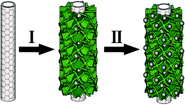 | ||
| Scheme 1 Schematic illustration of the Pt/CNT@TiO2 preparation process. | ||
The hierarchical CNT@TiO2 structure was successfully prepared by a solvothermal method followed by a post annealing process at 400 °C for 2 h. A typical scanning electron microscopy (SEM) image of the product is shown in Fig. 1a. The as-prepared CNT@TiO2 sample displays a one-dimensional carpenterworm-like structure. The diameter of the CNT@TiO2 structure is increased to ∼300 nm compared with that of the original CNT samples (∼150 nm, see ESI, Fig. S1†). The detailed morphology and structure of CNT@TiO2 were further studied by transmission electron microscopy (TEM). As can be seen in Fig. 1b, the TiO2 NSs appearing as a “hairy” structure are formed homogeneously along the longitudinal axis of CNTs. With a closer examination (inset of Fig. 1b), the TiO2 NSs are of hundreds of nanometres in width and only a few nanometres in thickness, with a relatively dense packing around the CNTs.55,56
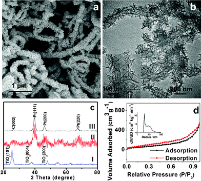 | ||
| Fig. 1 SEM (a) and TEM (b) images of CNT@TiO2.The inset of (b) shows the corresponding CNT@TiO2 hierarchical structure. (c) XRD patterns of CNT@TiO2 and the corresponding Pt catalyst (samples I: CNT@TiO2, II: Pt/CNT@TiO2, III: Pt/CNT). (d) N2 adsorption desorption isotherms of CNT@TiO2, The inset shows the pore size distribution calculated by the Barrett–Joyner–Halenda (BJH) method from the desorption branch. | ||
The constituent crystalline phases of the samples were analyzed by X-ray diffraction (XRD), and the result is shown in Fig. 1c. It is clear from pattern I that all the diffraction peaks can be assigned to anatase TiO2 (JCPDS 21-1272). The peak at about 2θ = 26° corresponding to (002) plane of CNTs almost overlaps with the (101) peak of anatase TiO2, making it difficult to discern from the current diffraction pattern. The content of CNTs in the hybrid materials was determined by thermogravimetric analysis (TGA), with the results shown in Fig. S2.† Apparently, the product shows the significant weight loss at ∼550 °C, which can be attributed to the combustion of the CNT backbone. Up to a temperature of 750 °C, the CNT@TiO2 sample shows a total weight loss of 44%.
Nitrogen adsorption/desorption measurements were also carried out to analyze the porous structure of the as-prepared CNT@TiO2 sample. Typical N2 adsorption isotherms are presented in Fig. 1d. A hysteresis loop can be observed between the relative pressure of 0.3 and 0.9, indicating the presence of mesopores in the product. As a result, the heterogeneous CNT@TiO2 with the hierarchical structure exhibits a large apparent specific surface area (SBET) of 170 m2 g−1 calculated by the Brunauer–Emmett–Teller (BET) method. Furthermore, the pores in the sample have a relatively narrow size distribution, mostly in the range of 4–20 nm, as shown in the inset of Fig. 1d.
SEM images (Fig. 2a, 2b) of Pt/CNT@TiO2 show that the CNT@TiO2 support remains the original one-dimensional hierarchical morphology. The Pt nanoparticles appear as the bright spots that are distributed uniformly on the surface of CNT@TiO2. The uniform distribution of Pt nanoparticles was further verified by TEM examination. As shown in Fig. 2c and d, it is evident that Pt nanoparticles with an average size of ∼3 nm are deposited uniformly on the CNT@TiO2 support (Fig. 2c, d and Fig. S3†). With the lower (20 wt%) Pt loading on CNT@TiO2, the structure of support can be seen more clearly (see ESI, Fig. S4†). The crystal interplane distance of Pt (111) is revealed by high-resolution TEM (HRTEM) to be 0.22 nm (Fig. 2e). The fast Fourier transform (FFT) pattern of face centered cubic Pt (111) is shown as the inset of Fig. 2e. The selected area electron diffraction (SAED) gives a pattern of bright spots arranged in coaxial rings (Fig. 2f), confirming the formation of Pt nanoparticles. The elemental mapping images of the as-prepared Pt/CNT@TiO2 nanocatalyst clearly demonstrate the uniform distributions of all the elements including Pt, Ti, C and O (see ESI, Fig. S5 and S6†).
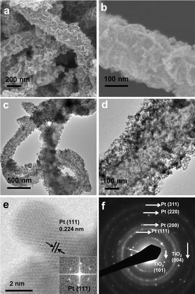 | ||
| Fig. 2 SEM (a, b) and TEM (c, d) images of Pt/CNT@TiO2 electrocatalysts. (e) HRTEM image of Pt/CNT@TiO2 showing the interplanar distance of Pt{111}. Inset shows the FFT pattern, corresponding to the Pt{111}. (f) SAED pattern of Pt/CNT@TiO2. | ||
The Pt composition in the nanocatalysts was also confirmed through XRD (Fig. 1c). Both catalysts (Pt/CNT and Pt/CNT@TiO2) show three Pt peaks at 2θ = 39.8, 46.2 and 67.4° corresponding to the (111), (200) and (220) planes, respectively. XRD results indicate that Pt nanocrystals manifest the face centered cubic (fcc) crystal structure which is in agreement with the above SAED pattern. The average particle size of Pt nanocrystals was estimated to be about 3.8 nm for Pt/CNT and 2.8 nm for Pt/CNT@TiO2 from the Scherrer's equation. It is consistent with the TEM images (Fig. 2) and the particle size distribution analysis (see ESI, Fig. S3†). Compared with Pt/CNT, the lower peak intensity of Pt/CNT@TiO2 might be ascribed to the smaller particle size.
The electrocatalytic activities were evaluated using the cyclic voltammetry (CV) technique. As shown in Fig. 3a, the CV profiles of Pt electrocatalysts exhibit hydrogen adsorption/desorption as well as oxides formation and reduction peaks, which are characteristic of a polycrystalline platinum electrode. The Pt/CNT@TiO2 nanocatalyst shows a slightly higher current density (4.3 mA cm−2) than Pt/CNT (4.1 mA cm−2), but the electrochemical active surface area (ESA) of both samples is nearly the same (∼70 m2 g−1, see ESI, Fig. S7 & S8†). In general, highly dispersed Pt nanocrystals with small size are important for their activity and stability.57 It was suggested that the high electrochemical activity of Pt/CNT@TiO2 could be attributed to the hierarchical nanostructured CNT@TiO2 support.58 Specifically, the large surface area (∼170 m2 g−1) could provide enough sites for loading of Pt nanoparticles with small size of ∼3 nm (Fig. 2 and ESI, Fig. S3–S5†), and the well-developed mesoporous structure (with pore size of 4–20 nm, Fig. 1d) could provide the channels for the rapid materials exchange during the reaction process. Furthermore, the “hairy” TiO2 NSs on the surface of CNTs would prevent them from forming large aggregates or bundles.
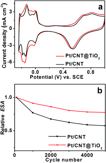 | ||
| Fig. 3 (a) Cyclic voltammograms of Pt/CNT and Pt/CNT@TiO2. The Pt loading on the electrode is 0.2 mg cm−2, and the potential sweep rate is 20 mV s−1. (b) The normalized electrochemical surface area (ESA) plots for the Pt/CNT and Pt/CNT@TiO2 electrocatalysts. | ||
In this CNT@TiO2 structure, the CNT backbone serves as the sufficient electrical conductor for the Pt nanocatalysts. In the absence of CNTs, there will be no characteristic hydrogen adsorption/desorption region for the Pt/TiO2 NSs (see ESI, Fig. S9†). This implies that Pt/TiO2 has poor catalytic activity likely because of the low conductivity of TiO2. However, the electrochemical results reveal that there is no large difference between the initial ESA of Pt/CNT and that of Pt/CNT@TiO2 (Fig. 3, and ESI, Fig. S7†). It was recently suggested that the increased activity of the Pt/CNT@TiO2 nanocatalyst is not caused by the increase in the catalytic area of Pt nanoparticles, but the addition of conductive CNT.59 Previous methods to improve the conductivity of Pt/metal oxides catalysts are to add conductive polymers or CB, which will most likely jeopardize the catalytic activity and/or stability.12,32,51,52,59 In the present nanocatalyst system, the CNT backbone provides good conductivity for the rapid electron transfer, thus the Pt/CNT@TiO2 has high ESA and catalytic activity.
The accelerated potential cycling tests (APCT) were conducted to evaluate the stability of these Pt nanocatalysts and the normalized ESA is present in Fig. 3b. After 5000 cycles, the ESA of Pt/CNT@TiO2 and Pt/CNT was retained at 78% and 57%, respectively. The APCT result reveals that the Pt/CNT@TiO2 nanocatalyst has a better stability than Pt/CNT, both of which show significantly improved stability compared to conventional Pt/CB (only 9% remained).28 In general, materials dissolution is thought to be the main factor influencing the stability of electrocatalysts,25,60 and the support degradation has a more significant effect than Pt dissolution on the stability of electrocatalysts.61–64 The ultrahigh stability of Pt/CNT@TiO2 could be attributed to the inherently excellent mechanical resistance and stability of TiO2 and CNTs in acidic and oxidative environments, strong metal-support interaction between Pt nanoparticles and the CNT@TiO2 support.59,65 Specifically, the hybrid CNT@TiO2 has high crystallinity because it was obtained after the heat treatment at 400 °C in air (see experimental). TGA results (see ESI, Fig. S2†) also indicate that the Pt/CNT@TiO2 only shows a weight loss above 450 °C, implying a good thermal stability of the nanocomposite. Moreover, it is evident from the XRD, SEM and TEM results that the CNT@TiO2 support is stable and remains the original morphology and structure even treated in the acidic environment at 140 °C for loading of the Pt nanocatalysts (Fig. 1, 2 and ESI, Fig. S4†). Furthermore, because of the strong metal-support interaction between Pt nanoparticles and the CNT@TiO2 support, Pt nanoparticles would be anchored on the TiO2 surface. As a result, their migration and agglomeration could be largely prevented.66 All these lead to the significantly enhanced stability of Pt nanocatalysts supported on CNT@TiO2.
Fig. 4 shows the CV curves for methanol (1M) electro-oxidation in a 0.5 M H2SO4 solution at a scan rate of 10 mV s−1. The forward peak current densities are ∼71 mA cm−2 for Pt/CNT@TiO2 and ∼25 mA cm−2 for Pt/CNT, confirming the greater catalytic activity of Pt/CNT@TiO2 than that of Pt/CNT (Fig. S7†). Chronoamperometric measurements were also carried out to investigate the electrochemical stability of Pt nanocatalysts for methanol oxidation. In Fig. 4b, the current density of methanol oxidation on the Pt/CNT@TiO2 nanocatalyst decreases slowly throughout the test, whereas the decay on the Pt/CNT nanocatalyst is much faster. The more gradual decay of current density implies that the Pt/CNT@TiO2 has a better anti-poisoning capability than Pt/CNT. The initial current drop may be due to the poisoning effect of CO-like intermediate species generated by the continuous oxidation process on the surface of nanocatalysts.35,67,68 The subsequent current density of Pt/CNT@TiO2 is higher than that of Pt/CNT throughout the measurement up to 1200 s, indicating that the Pt/CNT@TiO2 nanocatalyst is more active and stable than Pt/CNT for the methanol electro-oxidation. The stability result is consistent with the CV measurement (Fig. 3b). The higher current density and stability can be attributed to the beneficial effect of the TiO2 support.69 Because of the higher oxygen adsorption capacity of CNT@TiO2, hydroxyl groups can be easily produced on TiO2 surface, thus increasing the hydrophilicity of CNT@TiO2. This can facilitate the oxidation of the poisonous CO-like intermediates into CO2 and minimize the surface oxidation of Pt (Pt–OH formation) nanocatalysts.67,68,70,71 Therefore, the Pt/CNT@TiO2 has significantly improved catalytic activity and stability, and is more efficient for the electro-oxidation of methanol than Pt/CNT.
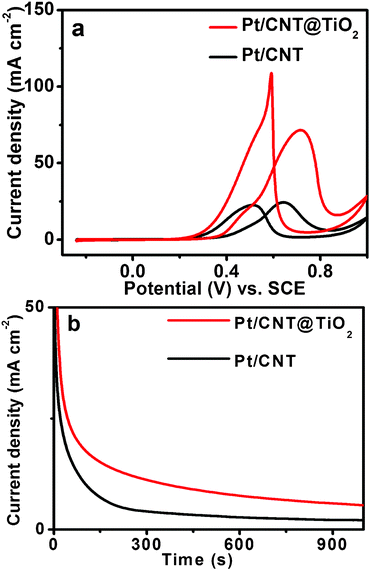 | ||
| Fig. 4 (a) Cyclic voltammograms of methanol oxidation on Pt/CNT and Pt/CNT@TiO2catalysts in 0.5M H2SO4 + 1M CH3OH solution, with the potential sweep rate of 10 mV s−1. (b) Chronoaperometry curves of Pt/CNT and Pt/CNT@TiO2 in 0.5 M H2SO4 + 1 M CH3OH solution recorded at 0.75 V. | ||
In summary, we have designed high-stability Pt electrocatalysts using hierarchical CNT@TiO2 structures composed of TiO2 nanosheets graphed on the CNT backbone as the support. The as-prepared Pt/CNT@TiO2 electrocatalysts manifest high electrocatalytic activity with greatly improved stability compared to conventional CNT or CB-supported Pt electrocatalysts. This could be ascribed to a possible synergetic effect of CNT and TiO2. In this designed electrocatalyst, TiO2 displays anti-corrosion and anti-poisoning functions for improved catalytic performance, while the CNT backbone provides a good conductivity for rapid electron transfer. The hybrid Pt/CNT@TiO2 electrocatalyst is a promising candidate to improve the reliability and stability for fuel cell applications. The design of Pt/CNT@TiO2 electrocatalysts with high activity and stability may provide some insights into further development of high-activity and high-stability Pt electrocatalyst for large scale use in low-temperature fuel cells.
Acknowledgements
X. Wang is grateful to the Ministry of Education (MOE) and the National Research Foundation (NRF) of Singapore for their funding support through the academic research fund AcRF Tier-2 (MOE2009-T2-2-024) and competitive research program (CRP, 2009NRF-CRP 001-032), respectively.References
- R. F. Service, Science, 2002, 296, 1222–1224 CrossRef CAS.
- G. Brumfiel, Nature, 2003, 422, 104–104 CrossRef CAS.
- R. Bashyam and P. Zelenay, Nature, 2006, 443, 63–66 CrossRef CAS.
- T. S. Ahmadi, Z. L. Wang, T. C. Green, A. Henglein and M. A. El-Sayed, Science, 1996, 272, 1924–1925 CAS.
- B. C. H. Steele and A. Heinzel, Nature, 2001, 414, 345–352 CrossRef CAS.
- H. P. Liang, H. M. Zhang, J. S. Hu, Y. G. Guo, L. J. Wan and C. L. Bai, Angew. Chem., Int. Ed., 2004, 43, 1540–1543 CrossRef CAS.
- R. Borup, J. Meyers, B. Pivovar, Y. S. Kim, R. Mukundan, N. Garland, D. Myers, M. Wilson, F. Garzon, D. Wood, P. Zelenay, K. More, K. Stroh, T. Zawodzinski, J. Boncella, J. E. McGrath, M. Inaba, K. Miyatake, M. Hori, K. Ota, Z. Ogumi, S. Miyata, A. Nishikata, Z. Siroma, Y. Uchimoto, K. Yasuda, K.-i. Kimijima and N. Iwashita, Chem. Rev., 2007, 107, 3904–3951 CrossRef CAS.
- H. A. Gasteiger and N. M. Marković, Science, 2009, 324, 48–49 CrossRef CAS.
- K. J. J. Mayrhofer and M. Arenz, Nat. Chem., 2009, 1, 518–519 CrossRef CAS.
- A. Chen and P. Holt-Hindle, Chem. Rev., 2010, 110, 3767–3804 CrossRef CAS.
- M. Tada, S. Murata, T. Asakoka, K. Hiroshima, K. Okumura, H. Tanida, T. Uruga, H. Nakanishi, S.-i. Matsumoto, Y. Inada, M. Nomura and Y. Iwasawa, Angew. Chem., Int. Ed., 2007, 46, 4310–4315 CrossRef CAS.
- Z. Z. Jiang, Z. B. Wang, D. M. Gu and E. S. Smotkin, Chem. Commun., 2010, 46, 6998–7000 RSC.
- E. Antolini, Mater. Chem. Phys., 2003, 78, 563–573 CrossRef CAS.
- H. R. Colón-Mercado, H. Kim and B. N. Popov, Electrochem. Commun., 2004, 6, 795–799 CrossRef.
- V. R. Stamenkovic, B. S. Mun, M. Arenz, K. J. J. Mayrhofer, C. A. Lucas, G. Wang, P. N. Ross and N. M. Markovic, Nat. Mater., 2007, 6, 241–247 CrossRef CAS.
- R. Srivastava, P. Mani, N. Hahn and P. Strasser, Angew. Chem., Int. Ed., 2007, 46, 8988–8991 CrossRef.
- S. C. Zignani, E. Antolini and E. R. Gonzalez, J. Power Sources, 2008, 182, 83–90 CrossRef CAS.
- S. Chen, P. J. Ferreira, W. Sheng, N. Yabuuchi, L. F. Allard and Y. Shao-Horn, J. Am. Chem. Soc., 2008, 130, 13818–13819 CrossRef CAS.
- G. Gupta, D. A. Slanac, P. Kumar, J. D. Wiggins-Camacho, X. Wang, S. Swinnea, K. L. More, S. Dai, K. J. Stevenson and K. P. Johnston, Chem. Mater., 2009, 21, 4515–4526 CrossRef CAS.
- Y. Shao, J. Liu, Y. Wang and Y. Lin, J. Mater. Chem., 2009, 19, 46–59 RSC.
- K. J. J. Mayrhofer, K. Hartl, V. Juhart and M. Arenz, J. Am. Chem. Soc., 2009, 131, 16348–16349 CrossRef CAS.
- J. Greeley, I. E. L. Stephens, A. S. Bondarenko, T. P. Johansson, H. A. Hansen, T. F. Jaramillo, J. Rossmeisl, I. Chorkendorff and J. K. Nørskov, Nat. Chem., 2009, 1, 552–556 CrossRef CAS.
- Y. Zhou, K. Neyerlin, T. S. Olson, S. Pylypenko, J. Bult, H. N. Dinh, T. Gennett, Z. Shao and R. O'Hayre, Energy Environ. Sci., 2010, 3, 1437–1446 CAS.
- J. S. Yu, S. Kang, S. B. Yoon and G. Chai, J. Am. Chem. Soc., 2002, 124, 9382–9383 CrossRef CAS.
- T. Hyeon, S. Han, Y. E. Sung, K. W. Park and Y. W. Kim, Angew. Chem., Int. Ed., 2003, 42, 4352–4356 CrossRef CAS.
- Y. Shao, G. Yin and Y. Gao, J. Power Sources, 2007, 171, 558–566 CrossRef CAS.
- B. Y. Xia, J. N. Wang, X. X. Wang, J. J. Niu, Z. M. Sheng, M. R. Hu and Q. C. Yu, Adv. Funct. Mater., 2008, 18, 1790–1798 CrossRef CAS.
- B. Y. Xia, J. N. Wang, S. J. Teng and X. X. Wang, Chem.–Eur. J., 2010, 16, 8268–8274 CrossRef CAS.
- S.-Y. Huang, P. Ganesan, S. Park and B. N. Popov, J. Am. Chem. Soc., 2009, 131, 13898–13899 CrossRef CAS.
- D. Wang, C. V. Subban, H. Wang, E. Rus, F. J. DiSalvo and H. D. Abrunña, J. Am. Chem. Soc., 2010, 132, 10218–10220 CrossRef CAS.
- Y. Q. Wang, Z. D. Wei, B. Gao, X. Q. Qi, L. Li, Q. Zhang and M. R. Xia, J. Power Sources, 2011, 196, 1132–1135 CrossRef CAS.
- S. Y. Huang, P. Ganesan and B. N. Popov, Appl. Catal., B, 2011, 102, 71–77 CrossRef CAS.
- Y. Y. Song, Z. D. Gao and P. Schmuki, Electrochem. Commun., 2011, 13, 290–293 CrossRef CAS.
- B. Park and E. J. Cairns, Electrochem. Commun., 2011, 13, 75–77 CrossRef CAS.
- A. Kowal, M. Li, M. Shao, K. Sasaki, M. B. Vukmirovic, J. Zhang, N. S. Marinkovic, P. Liu, A. I. Frenkel and R. R. Adzic, Nat. Mater., 2009, 8, 325–330 CrossRef CAS.
- W. Du, Q. Wang, C. A. LaScala, L. Zhang, D. Su, A. I. Frenkel, V. K. Mathur and X. Teng, J. Mater. Chem., 2011, 21, 8887–8892 RSC.
- B. Viswanathan, Catal. Today, 2009, 141, 52–55 CrossRef CAS.
- J. Zhao, W. Chen and Y. Zheng, Mater. Chem. Phys., 2009, 113, 591–595 CrossRef CAS.
- Y. Y. Chu, Z. B. Wang, Z. Z. Jiang, D. M. Gu and G. P. Yin, Adv. Mater., 2011, 23, 3100–3104 CrossRef CAS.
- L. Cao, F. Scheiba, C. Roth, F. Schweiger, C. Cremers, U. Stimming, H. Fuess, L. Chen, W. Zhu and X. Qiu, Angew. Chem., Int. Ed., 2006, 45, 5315–5319 CrossRef CAS.
- S. H. Huang, D. Susanti, D. S. Tsai, Y. C. Hsieh, Y. S. Huang and W. H. Chung, Langmuir, 2008, 24, 2785–2791 CrossRef CAS.
- H. Huang, D. Y. C. Leung and D. Ye, J. Mater. Chem., 2011, 21, 9647–9652 RSC.
- K. Kimura, H. Einaga and Y. Teraoka, Catal. Today, 2011, 164, 88–91 CrossRef CAS.
- X. Chen and S. S. Mao, Chem. Rev., 2007, 107, 2891–2959 CrossRef CAS.
- M. Gratzel, Nature, 2001, 414, 338–344 CrossRef CAS.
- C. V. Subban, Q. Zhou, A. Hu, T. E. Moylan, F. T. Wagner and F. J. DiSalvo, J. Am. Chem. Soc., 2010, 132, 17531–17536 CrossRef CAS.
- H. Song, X. Qiu, F. Li, W. Zhu and L. Chen, Electrochem. Commun., 2007, 9, 1416–1421 CrossRef CAS.
- E. Formo, E. Lee, D. Campbell and Y. Xia, Nano Lett., 2008, 8, 668–672 CrossRef CAS.
- S. Shanmugam and A. Gedanken, Small, 2007, 3, 1189–1193 CrossRef CAS.
- S.-E. Jang and H. Kim, J. Am. Chem. Soc., 2010, 132, 14700–14701 CrossRef CAS.
- J. H. Choi, K. W. Park, H. K. Lee, Y. M. Kim, J. S. Lee and Y. E. Sung, Electrochim. Acta, 2003, 48, 2781–2789 CrossRef CAS.
- M. K. Debe, A. K. Schmoeckel, G. D. Vernstrom and R. Atanasoski, J. Power Sources, 2006, 161, 1002–1011 CrossRef CAS.
- S. Ding, J. S. Chen and X. W. Lou, Adv. Funct. Mater., 2011, 21, 4120–4125 CrossRef CAS.
- B. Y. Xia, J. N. Wang and X. X. Wang, J. Phys. Chem. C, 2009, 113, 18115–18120 CAS.
- J. S. Chen, Y. L. Tan, C. M. Li, Y. L. Cheah, D. Luan, S. Madhavi, F. Y. C. Boey, L. A. Archer and X. W. Lou, J. Am. Chem. Soc., 2010, 132, 6124–6130 CrossRef CAS.
- J. S. Chen, H. Liu, S. Z. Qiao and X. W. Lou, J. Mater. Chem., 2011, 21, 5687–5692 RSC.
- A. T. Bell, Science, 2003, 299, 1688–1691 CrossRef CAS.
- D. R. Rolison, Science, 2003, 299, 1698–1701 CrossRef CAS.
- Z. Z. Jiang, Z. B. Wang, Y. Y. Chu, D. M. Gu and G. P. Yin, Energy Environ. Sci., 2011, 4, 2558–2566 CAS.
- S. Sun, G. Zhang, D. Geng, Y. Chen, R. Li, M. Cai and X. Sun, Angew. Chem., Int. Ed., 2011, 50, 422–426 CrossRef CAS.
- A. Kongkanand, S. Kuwabata, G. Girishkumar and P. Kamat, Langmuir, 2006, 22, 2392–2396 CrossRef CAS.
- Z. Chen, M. Waje, W. Li and Y. Yan, Angew. Chem., Int. Ed., 2007, 46, 4060–4063 CrossRef CAS.
- K. J. J. Mayrhofer, J. C. Meier, S. J. Ashton, G. K. H. Wiberg, F. Kraus, M. Hanzlik and M. Arenz, Electrochem. Commun., 2008, 10, 1144–1147 CrossRef CAS.
- F. A. de Bruijn, V. A. T. Dam and G. J. M. Janssen, Fuel Cells, 2008, 8, 3–22 CrossRef CAS.
- R. Kou, Y. Shao, D. Mei, Z. Nie, D. Wang, C. Wang, V. V. Viswanathan, S. Park, I. A. Aksay, Y. Lin, Y. Wang and J. Liu, J. Am. Chem. Soc., 2011, 133, 2541–2547 CrossRef CAS.
- Y. Bai, W. Li, C. Liu, Z. Yang, X. Feng, X. Lu and K. Y. Chan, J. Mater. Chem., 2009, 19, 7055–7061 RSC.
- S. J. Yoo, T. Y. Jeon, K. S. Lee, K. W. Park and Y. E. Sung, Chem. Commun., 2010, 46, 794–796 RSC.
- D. Eder, Chem. Rev., 2010, 110, 1348–1385 CrossRef CAS.
- E. Formo, Z. Peng, E. Lee, X. Lu, H. Yang and Y. Xia, J. Phys. Chem. C, 2008, 112, 9970–9975 CAS.
- M. Arenz, K. J. J. Mayrhofer, V. Stamenkovic, B. B. Blizanac, T. Tomoyuki, P. N. Ross and N. M. Markovic, J. Am. Chem. Soc., 2005, 127, 6819–6829 CrossRef CAS.
- J. M. Macak, P. J. Barczuk, H. Tsuchiya, M. Z. Nowakowska, A. Ghicov, M. Chojak, S. Bauer, S. Virtanen, P. J. Kulesza and P. Schmuki, Electrochem. Commun., 2005, 7, 1417–1422 CrossRef CAS.
Footnote |
| † Electronic supplementary information (ESI) available: Detailed experimental procedures, TGA, TEM, EDX pattern and elemental mapping images, as well as more electrochemical tests. See DOI: 10.1039/c1ra00587a |
| This journal is © The Royal Society of Chemistry 2012 |
