The alcohol-mediated reduction of CO2 and NaHCO3 into formate: a hydrogen transfer reduction of NaHCO3 with glycerine under alkaline hydrothermal conditions†
Zheng
Shen
ac,
Yalei
Zhang
*a and
Fangming
Jin
*b
aState Key Laboratory of Pollution Control and Resources Reuse, Key Laboratory of Yangtze River Water Environment of MOE, College of Environmental Science and Engineering, Tongji University, Shanghai, 200092, China. E-mail: zhangyalei@tongji.edu.cn;
bSchool of Environmental Science and Engineering, Shanghai Jiao Tong University, Shanghai 200240, China. E-mail: fmjin@sjtu.edu.cn
cState Key Laboratory of Catalysis Dalian Institute of Chemical Physics, Chinese Academy of Sciences, Dalian, 116023, China.
First published on 1st December 2011
Abstract
A hydrothermal method for the hydrogen-transfer reduction of CO2 or NaHCO3 is presented. This process uses glycerine as a reducing agent, which is ultimately converted to lactate, and can convert NaHCO3 into formate in about a 90% yield with respect to the initial amount of glycerine.
If carbon dioxide, a stable carbon end product of metabolism and other combustions, could be effectively reduced into useful organic products, it would provide an abundant, low-value carbon source to be recycled and reused.1 Significant efforts have been devoted to exploring technologies for CO2 transformation in which high free energy content substances (such as hydrogen, unsaturated compounds, small-membered ring compounds and organometallics) are required to compensate for the high thermodynamic stability and low energy level of CO2.2 In 1935, Farlow and Adkins reported the first direct hydrogen-transfer reduction of carbon dioxide to formic acid using H2 as a reductant and Raney nickel as a catalyst.3 Since then, the hydrogenation of carbon dioxide to form formic acid or formate salts has been widely investigated using homogenous or heterogeneous metal catalysts.4Formic acid is an important chemical feedstock and is used as a synthetic precursor and a commercial product in the leather, agriculture and dye industries. In addition, formic acid could be used as a raw material for hydrogen production and has the potential to power fuel cells to generate electricity and run automobiles.5 However, the production of CO2-derived formic acid is not widely used in industrial chemical processes because the reductant, H2, is currently produced from reactions of crude oil-derived methane with water. Therefore, the development of an alternative substance that can reduce CO2 is highly desirable.
Hydrothermal processes have been attracting increasing attention for use in organic chemical reactions because high-temperature water (HTW) is an environmentally benign solvent compared to organic solvents and has remarkable properties as a reaction medium.6 For example, HTW has a lower dielectric constant, fewer and weaker hydrogen bonds, and a higher isothermal compressibility than ambient liquid water.6a The solubility of most gases in liquid water initially decreases as the temperature is increased above ambient temperature, but a minimum solubility is soon reached, after which the gas solubility increases. For example, the minimal solubility of CO2 occurs at around 150 °C.6d Moreover, many organic reactions under ambient conditions only proceed in the presence of acidic/basic or metallic catalysts; however, these reactions can occur in HTW in the absence of an added catalyst.7
There is increasing interest in performing CO2 reductions in HTW8 because in this medium, H2 can be produced from metal or alcohol compounds. Horita and Berndt reported that CO2 is converted to CH4 by H2, which is formed under hydrothermal conditions (≤400 °C, ≤100 MPa) in a process catalysed by a hydrothermally formed nickel–iron alloy. In this system, H2 is produced during the conversion of olivine into serpentine and magnetite.8a It has also been found that formic acid can be hydrothermally produced from CO2 with Fe-powder and/or Ni-powder.8b–e He et al. have used iron nanoparticles not only as reducing agents but also as catalysts to transform CO2 into formic acid and acetic acid.8e For these metal reducing agents, however, the reactivity in HTW is low, and the yield of formic acid was less than 3%. Our recent research showed that in HTW, NaHCO3 is reduced to formate when isopropanol is used as a reducing agent.8f Based on this initial study, a higher yield of formate (about 70%) was obtained with isopropanol as a reducing agent than with metal reducing agents. Accordingly, it is likely that industrial applications of CO2 reduction would use abundant alcohol compounds as reducing materials.
Glycerine, namely 1,2,3-propanetriol, is a potentially important biorefinery feedstock and is a byproduct of biodiesel production. It is produced during the transesterification of vegetable oils or animal fats.9 In our previous study,10 we reported that glycerine is efficiently converted to lactic acid under alkaline hydrothermal conditions. In addition, H2 is produced in almost the same yield as lactic acid. Lactic acid is receiving attention as a material for producing biodegradable lactic acid polymers.11 We now report that NaHCO3 (as a source of CO2) is converted to a formate salt when glycerine is used as a reducing agent in HTW. Glycerine is converted to lactate under these reaction conditions. The effect of reaction conditions was also investigated in detail, e.g.NaHCO3 quantity, NaOH concentration, reaction temperature and time.
Glycerine (99%), NaHCO3 (99%) and NaOH (96%) were obtained from Wako Pure Chemical Industries, Osaka, and used as test materials. In this study, NaHCO3 was used as a CO2 resource to simplify operations and to allow for an accurate quantification of CO2.8d The schematic drawing of the experimental set-up can be found elsewhere.12 In addition to two experiments that studied the effect of reactor materials, most experiments were carried out in a batch reactor made of SUS 316 with an internal volume of 5.7 cm3, as has been previously described.12 Briefly, the desired amount of NaHCO3 (CO2 source), glycerine (reductant) and NaOH, if required, were loaded in a batch reactor and ultimately occupied 70% of the total reactor volume. The Glycerine concentration, NaOH concentration and NaHCO3 quantity were 0.33 M, 0–2.5 M and 0–1.76 g, respectively. After loading, the reactor was immersed in a salt bath, which had been preheated to the desired reaction temperature (300 °C). During the reaction, the reactor was shaken horizontally to enhance mixing and heat transfer. All experiments were performed with degassed water and in a reactor purged with nitrogen. After the predetermined reaction time (0–120 min), defined as the elapsed time during which the reactor was kept in the salt bath, the reactor was removed from the salt bath and cooled in a cold-water bath. The actual reaction time is shorter than the apparent reaction time because it took about 15 s to raise the temperature of the reaction medium from 20 to 300 °C. The reaction pressure was about 9 MPa in all experiments because they were performed at 300 °C and at a water fill of 70%.
After cooling, liquid and gaseous samples were collected for analysis. After being passed through a 0.45 mm filter, liquid samples were analysed by 1H-NMR and HPLC. 1H-NMR spectra were recorded on a JEOL JNM-LA500 spectrometer operating at 400 MHz. HPLC analyses were performed on two KC-811 (Shodex) columns with a RI detector and a UV detector (210 nm). The average value from HPLC analysis of at least three samples with less than 10% relative error was used to provide a quantitative estimation of the products.
First, a set of comparative experiments with glycerine and 0.25 M NaOH with or without dry ice (CO2 source) were carried out at 300 °C to determine whether CO2 could be reduced to formate under these conditions. In our previous studies, 300 °C was found to be an optimal temperature for hydrothermal reactions with glycerine.8f,10cHPLC traces of the reaction mixture are shown in Fig. 1. When one compares Fig. 1(a) to Fig. 1(b), it is clear that a large amount of formic acid was formed. The product yields and the remaining amounts of glycerine are detailed in Table 1. The product yield is defined as the percentage of the mole of products relative to the initial moles of glycerine reducing agent. As shown in Table 1 (a) and (b), the addition of dry ice resulted in a rapid increase in the formate yield and a relative decrease in H2 yield, but no substantial change is observed in the lactate yield. These results show that CO2 can be reduced to formate by glycerine under hydrothermal alkaline reaction conditions.
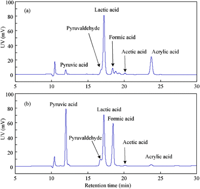 | ||
| Fig. 1 HPLC chromatograms of solutions after reaction of glycerine without or with dry ice (temp.: 300 °C; reaction time: 60 min; glycerine: 0.33 M; NaOH: 0.25 M; a: 0 g dry ice; b: 0.44 g dry ice). | ||
| a | b | c | d | |
|---|---|---|---|---|
| a 0.4 g NaOH. b 0.4 g NaOH and 0.44 g dry ice. c 0.84 g NaHCO3. d 1.06 g Na2CO3 (temp.: 300 °C; reaction time: 60 min; glycerine: 0.33 M). | ||||
| Lactate yield | 80.1% | 82.6% | 81.2% | 59.6% |
| Formate yield | 0.05% | 79.8% | 78.1% | 55.8% |
| Hydrogen yield | 84.5% | 4.0% | 3.8% | 3.1% |
| Pyruvate yield | 0.64% | 2.5% | 2.3% | 1.7% |
| Remaining glycerine | 16.0% | 14.1% | 15.2% | 36.7% |
In the next series of experiments, NaHCO3 was used as a CO2 source for several reasons. First, the use of NaHCO3 simplifies the experiments and allows for the accurate quantification of CO2.8d In addition, when CO2 is in alkaline conditions, it is readily converted to NaHCO3, so it is necessary to study the reduction process of NaHCO3 to enable the recycling of CO2 in future industrial applications. The results in Table 1 show that when NaHCO3 is used as a CO2 source, the product yields are comparable to or slightly lower than the yields obtained when dry ice is used as a CO2 source. Next, a series of experiments were performed to optimise reaction conditions by varying NaHCO3 quantity, NaOH concentration, reaction temperature and time. Because it has been reported that the addition of a base improves the reaction,13 and the conversion of glycerine into lactate is a base-catalysed reaction,10 the effect of NaOH concentration on the reduction process was determined.
The effects of NaHCO3 quantity and NaOH concentration on the glycerine-mediated reduction of NaHCO3 reduction under hydrothermal alkaline conditions are illustrated in Fig. 2 and Fig. 3, respectively. As shown in Fig. 2, the yields of both formate and lactate increase with higher quantities of NaHCO3. The curves show a clear increase when the initial NaHCO3 amount is 0.33 g or the mole ratio of NaHCO3 to glycerine is about 3, but the curves flatten when the NaHCO3 amount is 0.88 g or the ratio of NaHCO3/glycerine is 8. The results indicate that the initial quantity of NaHCO3 or the ratio of NaHCO3/glycerine is an important factor on the glycerine-mediated reduction of NaHCO3. This shows that glycerine is a stronger reductant because the optimal NaHCO3/isopropanol ratio is 12 on the hydrogen-transfer reduction of NaHCO3 with isopropanol.8fFig. 3 shows that an increase in NaOH concentration leads to a decrease in the formate yield, but the lactate yield is almost the same with the higher NaOH concentration. This may be because more NaHCO3 is converted to Na2CO3 at higher NaOH loadings. As shown in Table 1, the product yields when Na2CO3 is used as a CO2 source are lower than the yields when NaHCO3 is used. The lactate yield is relatively unchanged because the addition of NaOH does not substantially change the pH value of the solution.
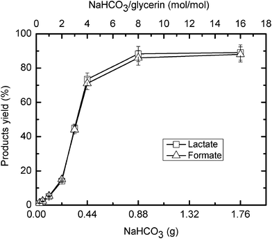 | ||
| Fig. 2 Effect of NaHCO3 quantity on the hydrogen-transfer reduction of NaHCO3 with glycerine (temp.: 300 °C; reaction time: 90 min; glycerine: 0.33 M). | ||
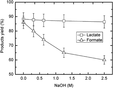 | ||
| Fig. 3 Effect of NaOH concentration on the hydrogen-transfer reduction of NaHCO3 with glycerine (temp.: 300 °C; reaction time: 90 min; glycerine: 0.33 M; NaHCO3: 0.88 g). | ||
The influence of reaction temperature and time were also studied at the optimal NaHCO3/glycerine ratio of 8. It can be seen in Fig. 4 that although the yields of formate and lactate at 260 °C or 280 °C were very low, the yields of both compounds increased when the reaction was held at 300 °C for extended reaction times. Under optimal conditions, a formate yield of about 90% was obtained, which is almost the same as the yield of lactate. These results show that NaHCO3 can be readily reduced and converted to formate by glycerine under alkaline hydrothermal conditions; under these conditions, glycerine is converted to lactate. It should be noted that the yield of formate from NaHCO3 reduction with glycerine as a reducing agent is considerably higher than the yield of formate with isopropanol in HTW.8f
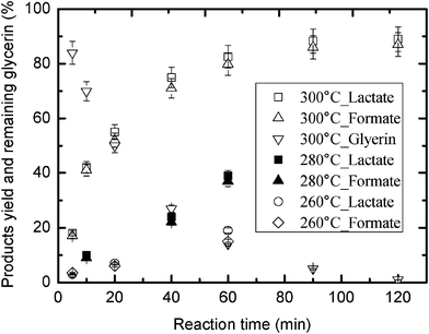 | ||
| Fig. 4 Effect of reaction temperature and time on the hydrogen-transfer reduction of NaHCO3 by glycerine (glycerine: 0.33 M; NaHCO3: 0.88 g). | ||
In order to investigate the catalysis effect of reactor materials on the hydrogen-transfer reduction of NaHCO3 with glycerine under hydrothermal alkaline conditions, we performed a series of experiments with a Teflon-line batch reactor with or without the addition of a small amount of SUS316 scrap.7f,10c After 24 h at 250 °C with 0.33 M glycerine and 0.88 g NaHCO3, the results showed that the formate and lactate yields with or without pieces of SUS316 were almost the same. Thus, it is likely that water molecules are acting as a catalyst for the hydrogen-transfer reduction of NaHCO3. To prove this, we carried out two anhydrous experiments with glycerine and dry ice at 300 °C with diethylamine or NaOH as a base, and we found that neither formate nor lactate was produced. However, both formate and lactate were detected by HPLC analysis in a hydrous experiment with glycerine and dry ice at 300 °C when diethylamine was used as a base. These results indicate that H2O other than NaOH may catalyse the reaction of the hydrogen-transfer reduction of NaHCO3 with glycerine.
Finally, the reaction pathway on the hydrogen-transfer reduction of NaHCO3 with glycerine was studied. As shown in Fig. 1, a small amount of pyruvaldehyde was detected. Pyruvaldehyde is likely an intermediate product, which undergoes a benzilic rearrangement to ultimately form lactic acid. This is a known conversion in sugar chemistry and has also been observed in hydrothermal reactions at 300 °C.7d,14 Although a detailed mechanism for the hydrogen-transfer reduction of NaHCO3 with glycerine cannot yet be deduced, an outline of a potential pathway is provided in Scheme 1; this pathway is based on the proposed mechanism for the hydrogen-transfer reduction of NaHCO3 with isopropanol8f and takes into account the same yields of formate and lactate, the catalytic role of water molecules, and the presence pyruvaldehyde.
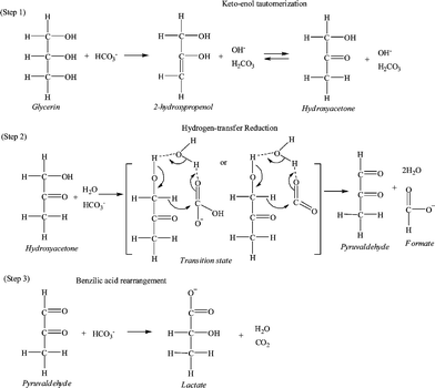 | ||
| Scheme 1 The proposed pathway of the hydrogen-transfer reduction of NaHCO3 with glycerine. | ||
In the first step, glycerine is dehydrated to produce 2-hydroxypropenol in E2 mechanism via a base attacking at the hydrogen of C–2 and then OH− elimination of C–1. Subsequently, hydroxyacetone is formed by keto–enol tautomerization of the produced 2-hydroxypropenol. In the second step, two hydrogen bonds may be formed among three molecules (hydroxyacetone, H2O, and HCO3− or CO2 from NaHCO3), which makes the carbonyl-carbon on HCO3− or CO2 and the hydride ion on the hydroxyacetone even more positive. Next, the hydride ion attacks the carbonyl-carbon, and a cyclic transition state may be formed. Finally, pyruvaldehyde and formate are formed, and a water molecule is regenerated after an intramolecular hydride shift. In the third step, pyruvaldehyde undergoes a benzilic acid rearrangement to form the lactate salt. In the proposed pathway, water molecules make a hydrogen-bond ring network with the substrate molecules, and the eight-membered ring transition state greatly lowers the energy for bond cleavage and formation. Similar water-catalysed mechanisms have been proposed in which hydrogen bonding between the substrates and water molecules forms a ring transition state in the reaction.7a,b,e,f
It is interesting that the peak of pyruvic acid in Fig. 1 (b) increased greatly compared to that in Fig. 1 (a). As shown in Table 1 (a) and (b), pyruvate yield increased to 2.5% from 0.64% by adding 0.44 g CO2. This finding suggests that in addition to the consecutive oxidation of pyruvaldehyde to form it,14apyruvic acid may be mainly obtained from hydrogen-transfer reduction of lactic acid and CO2 because the 2-hydroxyl group in lactic acid seems to act as that in isopranol.8f As a side reaction, this reaction pathway for production of pyruvic acid is shown in Scheme 2.
 | ||
| Scheme 2 The proposed pathway for production of pyruvic acid as a side reaction. | ||
In summary, we report a hydrothermal method for the hydrogen-transfer reduction of CO2 or NaHCO3 that offers some significant advantages over existing methods. The reported method uses glycerine as a reducing agent and permits the conversion of NaHCO3 into formate in about a 90% yield with concomitant production of a lactate salt. Another interesting aspect of this system is the simultaneous conversion of waste glycerine into lactic acid, which can be an intermediate for biodegradable polymers. The present work should accelerate studies for the industrial application of CO2 in which abundant alcohol compounds are used as reducing agents.
Acknowledgements
The authors gratefully acknowledge the financial support provided by the National Natural Science Foundation of China (Nos. 21006074, 20976139, 21077078), the National Key Technology R&D Program of China (Nos. 2009BAC62B02, 2009AA05Z405, 2009AA0639030), the Foundation of Key Laboratory of Yangtze River Water Environment of MOE in China (No. YRWEY1007), the Project of Shanghai Science and Technology Commission of China (Nos. 11QH1402600, 10230712400, 09JC1413900), the National Sparking Plan Project (No. 2010GA680011), the Research and Development Project of Ministry of Housing and Urban-Rural Development (No. 2011-K7-70), the Foundation of State Key Laboratory of Pollution Control and Resources Reuse of China (No. PCRRF11010), the Fundamental Research Funds for the Central Universities and the Science Foundation of China Postdoctor (No. 2011M500838).References
- (a) T. J. Marks, Chem. Rev., 2001, 101, 953 CrossRef; (b) T. Sakakura, J. C. Choi and H. Yasuda, Chem. Rev., 2007, 107, 2365 CrossRef CAS; (c) D. J. Darensbourg, Chem. Rev., 2007, 107, 2388 CrossRef CAS; (d) C. M. Rayner, Org. Process Res. Dev., 2007, 11, 121 CrossRef CAS; (e) M. Mikkelsen, Energy Environ. Sci., 2010, 3, 43–81 RSC.
- (a) D. H. Gibson, Chem. Rev., 1996, 96, 2063 CrossRef CAS; (b) T. Aida and S. Inoue, Acc. Chem. Res., 1996, 29, 39 CrossRef CAS; (c) P. G. Jessop, F. Jo and C. C. Tai, Coord. Chem. Rev., 2004, 248, 2425 CrossRef CAS; (d) G. A. Olah, Angew. Chem., 2005, 117, 2692 CrossRef; (e) N. Eghbali and C.-J. Li, Green Chem., 2007, 9, 213 RSC; (f) T. Ohishi, M. Nishiura and Z. Hou, Angew. Chem., 2008, 120, 5876 CrossRef.
- M. W. Farlow and H. Adkins, J. Am. Chem. Soc., 1935, 57, 2222 CrossRef CAS.
- (a) F. Gassner, J. Chem. Soc., Chem. Commun., 1993, 1465 RSC; (b) P. G. Jessop, J. Am. Chem. Soc., 1996, 118, 344 CrossRef CAS; (c) P. Munshi, J. Am. Chem. Soc., 2002, 124, 7963 CrossRef CAS; (d) P. G. Jessop, Chem. Rev., 2004, 248, 2425 CAS; (e) S. Ogo, Dalton Trans., 2006, 4657 RSC; (f) A. Urakawa, Chem.–Eur. J., 2007, 13, 3886 CrossRef CAS; (g) Y. Himeda, Organometallics, 2007, 26, 702 CrossRef CAS.
- (a) M. Weber, J. Electrochem. Soc., 1996, 143, 158 CrossRef; (b) N. Akiya and P. E. Savage, AIChE J., 1998, 44, 405 CrossRef CAS; (c) J. Yu and P. E. Savage, Ind. Eng. Chem. Res., 1998, 37, 2 CrossRef CAS; (d) C. Rice, J. Power Sources, 2002, 111, 83 CrossRef CAS; (e) S. Uhm, S. T. Chung and J. Lee, J. Power Sources, 2008, 178, 34 CrossRef CAS.
- (a) R. W. Shaw, Chem. & Eng. News, 1991, 69, 26 CAS; (b) N. Akiya and P. E. Savage, Chem. Rev., 2002, 102, 2725 CrossRef CAS; (c) M. Watanabe, Chem. Rev., 2004, 104, 5803 CrossRef CAS; (d) S. E. Hunter and P. E. Savage, AIChE J., 2008, 54, 516 CrossRef CAS.
- (a) H. Takahashi, S. Hisaoka and T. Nitta, Chem. Phys. Lett., 2002, 363, 80 CrossRef CAS; (b) T. Arita, Tetrahedron Lett., 2003, 44, 1083 CrossRef CAS; (c) B. Kuhlmann, E. M. Arnett and M. Siskin, J. Org. Chem., 1994, 59, 3098 CrossRef CAS; (d) F. M. Jin, Chem. Lett., 2004, 33, 126 CrossRef CAS; (e) Z. Shen, J. Zhejiang Univ., Sci., A, 2009, 10, 1631 CrossRef CAS; (f) Z. Shen, Ind. Eng. Chem. Res., 2010, 49, 6255 CrossRef CAS.
- (a) J. Horita and M. E. Berndt, Science, 1999, 285, 1055 CrossRef; (b) H. Takahashi, J. Mater. Sci., 2008, 43, 2487 CrossRef CAS; (c) H. Takahashi, J. Mater. Sci., 2006, 41, 1585 CrossRef CAS; (d) B. Wu, Catal. Today, 2009, 148, 405 CrossRef CAS; (e) C. He, Org. Lett., 2010, 12, 649 CrossRef CAS; (f) Z. Shen, Green Chem., 2011, 13, 820 RSC; (g) F. Jin, et al. , Energy Environ. Sci., 2011, 4, 881 RSC.
- (a) A. Behr, J. Eilting, J. Leschinski and F. Lindner, Green Chem., 2008, 10, 13 RSC; (b) Y. G. Zheng, X. L. Chen and Y. C. Shen, Chem. Rev., 2008, 108, 5253 CrossRef CAS.
- (a) H. Kishida, Chem. Lett., 2005, 34, 1560 CrossRef CAS; (b) H. Kishida, F. M. Jin, T. Moriya and H. Enomoto, Kagaku Kogaku Ronbunshu, 2006, 32, 535 CrossRef CAS; (c) Z. Shen, Ind. Eng. Chem. Res., 2009, 48, 8920 CrossRef CAS.
- W. Amass, A. Amass and B. Tighe, Polym., 1998, 47, 89–144 CAS.
- (a) F. Jin, A. Kishita, T. Moriya and H. Enomoto, J. Supercrit. Fluids, 2001, 19, 251 CrossRef CAS; (b) F. Jin, T. Moriya and H. Enomoto, Environ. Sci. Technol., 2003, 37, 3220 CrossRef CAS.
- (a) Y. Inoue, Chem. Lett., 1976, 863 CrossRef CAS; (b) K. Kudo, N. Sugita and Y. Takezaki, Nippon Kagaku Kaishi, 1977, 302 CrossRef CAS; (c) H. Hashimoto and Y. Inoue, Japan Kokai Tokkyo Koho, 1978, 7612 Search PubMed.
- (a) M. Ai and K. Ohdan, Bull. Chem. Soc. Jpn., 1999, 72, 2143 CrossRef CAS; (b) F. Jin and H. Enomoto, Energy Environ. Sci., 2011, 4, 382 RSC.
Footnote |
| † Electronic supplementary information (ESI) available. See DOI: 10.1039/c1ra00886b |
| This journal is © The Royal Society of Chemistry 2012 |
