On the formation of aggregates in silica–rhodamine 6G type II hybrids†
Carlo M.
Carbonaro
*ab,
Pier Carlo
Ricci
a,
Stefania
Grandi
c,
Marco
Marceddu
b,
Riccardo
Corpino
ab,
Marcello
Salis
a and
Alberto
Anedda
ab
aDepartment of Physics, University of Cagliari, sp n°8 km 0.700, 09042, Monserrato, Italy. E-mail: cm.carbonaro@dsf.unica.it; Fax: +39 070 510171; Tel: +39 070 6754823
bC. G. S. c/o Department of Physics, University of Cagliari, sp n°8 km 0.700, 09042, Monserrato, Italy
cCNR–IENI c/o Department of Chemistry, University of Pavia, 16 v. Taramelli, 27100, Pavia, Italy
First published on 6th January 2012
Abstract
The spectroscopic features of dye aggregates in organic–inorganic Rhodamine 6G–silica hybrids are investigated in sol–gel prepared type II bulk and thick film samples in the 10−4–10−3 mol l−1 concentration range. No aggregates are observed in film samples irrespective of the dye concentration and the spectroscopic features are ascribed to fluorescent monomers. On the contrary, by means of excitation and emission fluorescence measurements and the analysis of fluorescence decay kinetics the formation of fluorescent aggregates is reported in bulk samples and the geometry of the formed aggregates at the silica surface is discussed on the single exciton theory framework. Beside the distribution of a single emitting specie observed in bulk samples and individuated as oblique J dimers, the analysis of the excitation spectra indicate also the presence of “dark” monomer units. An energy transfer mechanism is hypothesized to explain the interaction of the monomer–dimer pair.
Introduction
By means of sol–gel technique organic–inorganic hybrids, both as bulk and film samples, can be easily engineered to address specific requirements in numerous technological fields, from the health care to the environmental control.1–3 A large content of chosen dye molecules can be introduced within porous inorganic matrix characterized by large specific surface area allowing to exploit the concentration effect to increase the performances of the designed hybrid. The main drawback is the formation of organic aggregates, the extent of which strongly depends on the host–guest interaction: indeed the presence of the external potential, represented by the porous surface, is the leading force in the concentration dependent formation of molecular aggregates. The final chemical–physical properties of the synthesized hybrid depend on the interaction among the dye molecules and the porous surface so that the possibility to control this interaction and, consequently, the formation of aggregates is a technological challenge.4In the last decades fluorescent dyes were introduced in mesoporous silica matrix aiming to realize luminescent materials for photonic applications.5–13 The silica-based hybrid model here investigated contains Rhodamine 6G (Rh6G), a well studied Xanthene dye known for its high quantum yield and its laser tunability in the 550–600 nm.14 To synthesize the desired hybrids there are two main routes: the impregnation of sol–gel prepared transparent porous silica matrix by means of alcoholic solutions containing the chosen dye (post-doping method) or the so-called “one-pot” synthesis, where the dye molecules are introduced at the sol stage of the sol–gel technique (pre-doping method). The host–guest interaction in pre- and post-doping synthesized hybrids is via electrostatic bonds and the formed hybrids are classified as type I. Recently we have shown the possibility, within the one-pot synthesis, to design a specific precursor of the Rh6G and to obtain type II hybrids where the host–guest interaction is realized through covalent bonds.15 Type II hybrids showed chemical physical properties that promote them as good candidates for fluorescence applications: in particular the main features of these hybrids, as compared to type I, are the almost total lack of leaching, even at very large dye concentration, and their larger photostability. Both these characteristics are valuable in view of possible applications in photonics, as active media for solid state dye laser, or as fluorescent probe in the biological field. Besides, a third required property is the brightness of the material, here achieved by increasing the dye concentration up to 10−3 mol l−1. However, large dye content causes aggregation phenomena of dye molecules, urging a deeper characterization of the spectroscopic features of type II samples concerning this aspect. Indeed the optical properties of Rh6G–silica type I hybrid are well documented,5–11,16–20 and typically interpreted within the framework of the single exciton theory.21–22 Aggregation phenomena were also reported in parent systems where the dye molecules were introduced within layered clays showing the formation of different types of aggregates.23–28 The formation of fluorescent dimers are reported in the 10−5–10−4 mol l−1 concentration range and above this threshold the transition to non-fluorescent aggregates was observed.5–11 The formation of dimers can be deduced from the absorption and emission properties of the system: as compared to monomer species, non-fluorescent H dimers are characterized by a blue shifted absorption band (called H–band) with respect to the monomer absorption band and fluorescent J dimers are characterized by a red shifted emission band with respect to the monomer emission band (from the so called J–band). The configuration of H dimers is a coplanar sandwich arrangement with an angle between the monomer transition moments and the silica surface larger than 54.7°. By contrast, J dimers display both a coplanar sandwich configuration or an oblique head-to-tail configuration with the reference angle smaller than 54.7°.21,22,29,30
The configuration adopted by fluorescent J dimers depends on the host–guest interaction29–32 and can be discriminated by the excitation properties: oblique J dimers have two allowed singlet–singlet electronic transitions to both the excited states (H and J bands), red and blue shifted with respect to the excitation band of the monomer emission, while in coplanar J dimers a single red shifted excitation band is observed. By means of optical spectroscopy investigation one can assess the presence of different aggregates in the system under study and exploit their luminescent properties for specific applications: the formation of different kind of J dimers allows, in principle, to extend the wavelength and time tunability of the luminescent system.5–11 For example, the presence of J aggregates of polymethine dyes was exploited to produce laser active media.33 Thus the possibility to control the aggregation state of Rh6G in dye-doped silica hybrids represents a target for a larger technological application of these systems. Typically the aggregation of Xanthene dyes in sol–gel silica is realized with oblique J dimers but for Rhodamine 101, where coplanar J dimers were observed because of its molecular structure.10 It was also reported that coplanar J dimers can be induced in Rhodamine 110-silica hybrids by decreasing the specific surface area of the host matrix.8 In the mentioned studies the investigated samples were type I hybrids. In the present paper we studied the formation of aggregates in Rh6G–silica type II hybrids in the 10−4–10−3 mol l−1 concentration range, that is just within the expected limit of the transition from J to H dimers. The aim of the work is to characterize the geometry of the aggregates in these systems, to analyze the transition from fluorescent to non fluorescent dimers and to exploit the possibility of controlling the formation of aggregates by post synthesis bleaching techniques. The aggregation effect is discussed by comparing thick film and bulk type II hybrids.
Results and discussion
The fluorescent properties of J dimers in Rh6G-silica samples allow to investigate and discuss their spectroscopic properties in the framework of the exciton theory by recording the PL and PLE spectra and by analyzing the decay time of the recorded emissions. PL spectra of the hybrid samples are reported in Fig. 1 and Fig. 2, recorded at different dye concentration (fixed excitation) and excited at different excitation wavelength (fixed dye concentration). As previously reported for type I silica–Rh6G hybrids, a spectral shift of the PL emission is recorded as a function of the dye concentration: as the dye concentration increases the emission peak of the PL spectra (λexc = 337 nm) displays a bathocromic shift of about 5 nm (Fig. 1). The figure reports an enlarged view of the normalized PL peak, the whole PL spectrum of the S2 samples is reported in the inset for completeness. The figure also reports the geometric and molecular structure of Rh6G (H white, C gray, O red, N blue). | ||
| Fig. 1 Enlarged view of normalized PL spectra of type II hybrids at different Rh6G concentration, excited at 337 nm. Inset: whole PL spectrum of S2 samples. In the middle geometric and molecular structure of Rh6G (H white, C gray, O red, N blue). | ||
![Enlarged view of normalized PL spectra of type II hybrids at different excitation wavelengths for the S2 samples ([Rh6G] = 5.0 × 10⁻⁴ mol l−1). In the middle: sketch of dimer geometry at silica surface. Inset: energy level scheme of monomer and oblique J dimer (solid lines are excitations, dashed line emissions)](/image/article/2012/RA/c2ra00830k/c2ra00830k-f2.gif) | ||
| Fig. 2 Enlarged view of normalized PL spectra of type II hybrids at different excitation wavelengths for the S2 samples ([Rh6G] = 5.0 × 10⁻⁴ mol l−1). In the middle: sketch of dimer geometry at silica surface. Inset: energy level scheme of monomer and oblique J dimer (solid lines are excitations, dashed line emissions) | ||
By recording the PL emission excited a different excitation wavelengths, the emission peak undergoes spectral shift (Fig. 2, the spectra refer to S2 samples, [Rh6G] = 5.0 × 10⁻⁴ mol l−1; similar results also hold for the other samples): a bathocromic shift of about 6 nm is detected in the PL spectrum when decreasing the excitation wavelength from 533 to 471 nm. However when exciting at 337 nm the emission peak shifts back to 559 nm. In the figure a schematic picture of the dimer aggregates is also reported, to sketch the geometry of (a) H dimer, (b) coplanar J dimer, (c) oblique J dimer. According to the exciton theory, the simplified energy level scheme reported on the top of the figure refers to the monomer and the oblique J dimer (solid lines are excitation transitions, dashed lines emission transitions): as discussed in the introduction, in the case of non fluorescent H dimer the absorption transition to the H band is the only allowed transition, while in the case of oblique fluorescent J dimer the transitions to and from the J band are also observed.
The spectroscopic features of Rh6G molecules in the monomer form are well known: the main absorption peak (S0–S1 transition) is peaked at 530 nm, with a vibronic shoulder around 500 nm.14 The emission band is peaked at about 550 nm. The decay time of the fluorescence is about 3.8 ns when the dye is hosted in silica matrix because of the reduced mobility with respect to the ethanol solution (decay time 3.0 ns).9,34 A second excitation channel in the UV range (300–360 nm) is related to the S0–S2 transition.
In Table 1 the spectroscopic features of the investigated samples under UV excitation are reported. We can observe that the emission properties of Rh6G monomers are retrieved in the film samples where no spectral shift was recorded by changing the excitation wavelength nor the dye concentration (see ESI, Fig. S1†). These results were somehow expected since the absorption spectra of the film samples do show increase with dye content without spectral modification.17 The observed spectral shift in bulk samples as a function of the Rh6G concentration (at fixed excitation wavelength) or as a function of the excitation light source (at fixed concentration) can be related to the presence of different emitting species whose emission and excitation peaks are red and blue shifted respectively as compared to that of the monomer ones, that is it calls for the formation of fluorescent dimers. A different possible explanation is the re-absorption effect due to the large dye concentration range investigated, even though the front-face geometry applied to record the emission spectra should largely reduce this effect.5–11,36
| Sample | λ em (nm)–FWHM (nm) | τ (ns) | QY |
|---|---|---|---|
| S1 | 557–39 | 5.53 | 0.71 |
| S2 | 559–43 | 5.46 | 0.52 |
| S3 | 560–40 | 5.26 | 0.22 |
| S4 | 561–44 | 4.17 | 0.21 |
| Film | 553–43 | 3.15 | 0.95 |
In order to ascertain the right interpretation of the reported data we carried out PLE measurements on S1 and S4 samples (Fig. 3, [Rh6G] = 1.4 × 10⁻⁴ and 1.6 × 10⁻³ mol l−1, respectively) by recording the excitation spectra along the whole emission profile. The figure reports the contour plots in the 520–640 nm emission range. The spectra extracted from the reported plots are shown in the ESI (Fig. S2†). In Fig. S2 the PLE spectrum of a film sample recorded by monitoring the 550 nm emission is also reported for comparison, showing the expected monomeric excitation band at 530 nm and the vibronic shoulder at about 500 nm. By comparison, the PLE spectrum of the S1 sample at 550 nm displays a broader excitation band also peaked at about 530 nm with a large shoulder below 500 nm whose relative intensity increases and its spectral position blue shifts by monitoring emissions of increasing wavelengths. In addition the peak of the main excitation band red shifts and the band displays a larger bandwidth for larger emission wavelengths. These spectral changes are better displayed by the S4 sample where the two excitation channels even undergo a clear spectral separation as the monitored emission increases.
 | ||
| Fig. 3 Contour plot of PLE spectra of S1 and S4 samples in the 520–640 nm emission wavelength range. The PLE spectra at different emissions extracted form the present plots are reported in the ESI (Fig. S2†) together with the spectrum of a film sample (λem = 550 nm) for comparison. | ||
The PLE data are in good agreement with the recorded absorbance spectra reported in Fig. 4 where the broadening of the main excitation and the increase of the blue absorption band by increasing the dye concentration is shown.
 | ||
| Fig. 4 Normalized absorbance spectra of S1 and S4 samples in the 400–600 nm range. | ||
These experimental findings can be interpreted according to the exciton theory and taking into account the dye concentration range under investigation: the recorded fluorescent properties can be ascribed to the presence of fluorescent J dimers and the observation of two excitation channels, red and blue shifted with respect to the monomer peak, allows to identify these J dimers as oblique ones.
To further proceed in the characterization of the emission properties of type II Rh6G–silica hybrids we carried out TR-PL measurements. Fig. 5 reports the emission spectra recorded at different time delays from the zero time excitation pulse, namely 3.2 and 12.5 ns after the excitation pulse, respectively: since the two spectra do not show spectral changes we can deduce that the observed emission is related to a single emitting species. Indeed, as reported in the inset of the figure, the time decay of the PL intensity can be successfully fitted with a single exponential decay. The fitting results were calculated by applying the fitting procedure to the PL intensity integrated over the whole spectral range and are reported in Table 1 (square correlation factor R2 > 0.98). The estimated decay time of bulk samples decreases as the dye concentration increases, indicating the increase of the nonradiative pathways: within the single exciton theory framework it can be interpreted as the fingerprint of the formation of non fluorescent H dimers beside the fluorescent J dimers. The increasing presence of nonradiative pathways is also confirmed by the emission quantum yield (QY) estimated by comparison with ethanolic solution of Rh6G of comparable dye concentration (see ESI†).35 On the contrary, the estimated decay time of the monomeric PL emission recorded in thick film samples keeps constant irrespective of the dye concentration, as expected, and was calculated to be about 3.2 ns. One should note that the calculated value of the decay time is smaller than the one estimated for bulk samples and also of the one reported for fluorescent Rh6G monomer in type I bulk samples.9 This finding indicates a less restricted environment for the dye molecules, even though a more compacted matrix should be expected in thick film samples because of the fast gelation procedure. Comparable results were also obtained with type I thick film samples (here not reported) suggesting that a more compacted matrix is able to isolate one molecule from the others even in the large concentration range investigated, allowing to preserve monomer emitting species in these samples.
 | ||
| Fig. 5 Upper panel: PL spectra of S4 samples recorded at different time delay from the excitation pulse. Inset: Decay time plot of S1 and S4 samples. Lower panel: calculated lifetime at different emission wavelengths (the dotted line is the calculated value for the integrated PL intensity). The excitation light was 337 nm | ||
One should bear in mind that the detected spectroscopic characteristics are related to a distribution of emitting fluorescent J dimers on the silica surface (aggregates of larger units are not considered). Indeed the calculated decay times are to be regarded as mean values, since the discrimination among the contribution of different emitting species was unsuccessful: the whole set of decay times was fitted with a single exponential decay, a clear indication of a continuous distribution of aggregates with comparable average decay time. This is further confirmed by the analysis reported in the lower panel of Fig. 5 where the calculated decay times at different emission wavelength along the emission profile are reported. The following procedure was applied: the PL intensity of the emission band recorded by the streak camera was integrated over a small wavelength window (about 7 nm) to collect the decay plot at different emission wavelengths. The decay profiles were fitted by a single exponential law and the calculated decay times are reported as a function of the emission wavelength. The dotted line is the value calculated by fitting the whole PL spectrum and reported in Table 1. As indicated by the plot reported in the figure, the estimated values are scattered in the 520–640 emission range around the lifetime mean value evaluated for the integrated signal with maximum deviation within 10% of this value, confirming a distribution of emitting J dimers.
Since PLE spectra displayed blue and red excitation channels, TR-PL measurements were carried out also at 471 nm, 533 nm and 575 nm. The calculated decay times are reported in Table 2 (square correlation factor R2 > 0.95), the details of the fitting procedure are summarized in the ESI.† When exciting at 471 nm the emission band was merely detectable for the samples with the larger dye concentration because of the large absorption and no attempt was performed to fit the data. The same also holds for the S1 and S2 samples when exciting at 575 nm but for the opposite reason, that is the negligible absorption at this excitation wavelength (see Fig. 4). In the whole set of experiments the fitting procedure disclosed a single exponential decay, indicating the presence of a single emitting specie.
| Sample | λ exc = 337 nm | λ exc = 471 nm | λ exc = 533 nm | λ exc = 575 nm |
|---|---|---|---|---|
| S1 | 5.53 | 4.59 | 2.67 | — |
| S2 | 5.46 | 4.21 | 3.45 | — |
| S3 | 5.26 | 4.05 | 3.47 | 4.83 |
| S4 | 4.17 | — | 3.22 | 4.23 |
In addition the decrease of the estimated decay time as the dye concentration increases is recorded for all the excitations but for the S1 samples under 533 nm excitation, an indication of the increasing contribution of nonradiative centres. The different values obtained for the lifetimes can be interpreted in terms of a distribution of emitting J dimers with slightly different spectroscopic features: by exciting at different excitation wavelengths we preferentially excite a specific sub-group of the distribution, thus recording the reported spectral and lifetime variations. Indeed the definition of the adsorption surface in porous media is non trivial and a large distribution of J dimers with slightly different spectroscopic features should be expected.
It was reported in the literature that the geometric distribution of J dimers can be modified in Rhodamine 110 doped sol–gel glass by reducing the specific surface area (SSA) or by thermal treatment in the case of Rh6G type I hybrids.8,37 One can hypothesize that post synthesis treatments, such as the water rinsing typically applied to eventually remove Rh6G molecules non grafted at the silica surface, could also modify the geometry of the emitting species, since it can change both the porosity and the SSA or the residual content of trapped solvent within the pores.17 In Fig. 6 the contour plots of the PLE spectra recorded in S4 samples after the water rinsing procedure are reported in the 520–640 nm emission wavelength range. The spectra extracted from the reported plots are shown in the ESI (Fig. S3†), together with the PLE spectra of S2 samples after water rinsing procedure and the PLE spectrum of a film sample (λem = 550 nm) for comparison. As compared to PLE spectra of the as synthesized hybrids (Fig. 3) we can observe that the procedure does not affect the excitation profiles in the case of the lowest dye concentration (S1, see Fig. S3†) but largely affect the samples with the largest one (S4). Indeed in this case the broad PLE channel around 550 nm is replaced by a narrower band peaked at about 570 nm and the spectral separation between the two main excitation channels is largely increased. The water rinsing treatment was applied to the samples to verify the efficiency of the type II synthesis to realize a covalent bond between the dye molecules and the silica surface. The PLE spectra showed that the post synthesis procedure largely affect the samples with largest concentration, suggesting a large reorganization of the emitting centres. Almost no effects were recorded in the samples with the smallest dye concentration, where no leached molecules were detected in the rinsed water, while the leaching effect in S4 samples was estimated of about 5% of the pristine dye concentration.15
 | ||
| Fig. 6 Contour plot of PLE spectra of S4 samples in the 520–640 nm emission wavelength range after water rinsing post synthesis treatment. The PLE spectra at different emissions extracted from the present plot are reported in the ESI (Fig. S3†) together with the spectrum of a film sample (λem = 550 nm) for comparison. | ||
In order to better analyze the effect of the water rinsing procedure, we performed a spectral subtraction to put in evidence the contribution removed by the post synthesis procedure. The PLE spectra of S4 samples before and after the rinsing treatment are compared for a specific emission wavelength, namely 620 nm (Fig. 7a), and the result of their spectral subtraction is reported together with the PLE spectrum of monomer species recorded in the film samples (Fig. 7b): the difference spectrum is very similar to the PLE spectrum recorded in film samples calling for the presence of monomers at least in the raw S4 hybrids. In addition the performed analysis indicates that the post synthesis procedure removes the contribution of not grafted monomers. Indeed it was reported in the literature that, in order to obtain the true excitation spectrum of dimers, the spectral subtraction of the monomer contribution, previous a normalization to the monomer excitation peak, should be performed.9,31,32 The result is reported in Fig. 8 for the S4 samples before and after the water rinsing treatment: the obtained excitation spectrum is the same in both cases. The analysis assumes that the monomer excitation contribution is present in both the samples and shows that the two samples only differ for a different relative contribution of monomers. The PLE spectra reported in Fig. 8 can be further analyzed in the framework of the exciton theory to extract information on the geometry of the emitting oblique J dimers. The angle and the distance between the monomer transition moments of oblique fluorescent dimers, α and R (expressed in Å) respectively, can be evaluated by means of the following equations:9,31,32,38
| tan2 (α/2) = A1/A2 | (1) |
| U = (v1 − v2)/2 | (2) |
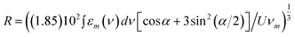 | (3) |
 | ||
| Fig. 7 PLE spectra of S4 samples before and after the rinsing treatment, at 620 nm (a), spectral difference between the S4 PLE spectra and PLE spectrum of film samples (b). | ||
 | ||
| Fig. 8 PLE spectra of S4 sample before and after water rinsing treatment after subtraction of monomer PLE spectrum previously normalized to the monomer excitation peak (see text for details). | ||
A Gaussian fit procedure with two Gaussian bands (R2 > 0.92) was applied, in the energy space, to the PLE spectra reported in Fig. 8 and to the PLE spectra of S1 samples subjected to the same spectral subtraction, in order to evaluate the relative contribution of the two excitation channels and their spectral separation. The distance between the monomer units was calculated by estimating the molar absorption coefficient integral from the film samples. The calculated values according to eqn 1–3 are listed in Table 3, data between brackets refer to the PLE spectra recorded by monitoring the 550 nm emission. Since the blue and red excitation bands undergo an increasing spectral separation by monitoring increasing emission wavelengths in the 550–620 nm range (Fig. 3 and Fig. 6), by applying the Gaussian fitting procedure to the respective PLE spectra a distribution of the geometric parameters is obtained, as reported in Table 3, confirming the presence of a distribution of emitting J dimers. In particular one can observe that the distance between monomer units decreases by increasing both the dye concentration or the monitored emission wavelength while the angle increases almost up to the 70° magic angle typically expected for the formation of oblique fluorescent aggregates.9,21,22 In addition, the calculated R distance and the splitting between the two excitation bands are quite larger than the values reported in comparable type I hybrids.9,11,38 The reported results can be also compared to the ones of hybrid silica-based systems where Rhodamine B and Nile Red nanoparticles were embedded.39,40 Indeed in the present case the porous surface is covered by organic moieties to which the Rh6G molecules are covalently bonded instead of silanol groups as in type I systems. From this point of view the surrounding environment sensed by the dye molecules looks like the one of embedded dye nanoparticles. Indeed in those systems the formation of oblique J dimers was reported and claimed as a pre-requisite for the supramolecular architecture. However, in the present case, the decrease of the QY indicates also the formation of nonradiative pathways, such as H dimers, which prevents the enhancement of the emission observed in the nanoparticle cases: because of the covalent bond the growth of highly fluorescent nanoparticles is precluded.
| Sample | ν 1 (cm−1) | ν 2 (cm−1) | U (cm−1) | α (°) | R (Å) |
|---|---|---|---|---|---|
| S1 | 21149 (20829) | 18159 (18298) | 1495.0 (1265.5) | 58.1 (42.7) | 14.9 (15.1) |
| S4 | 22467 (21048) | 17934 (19291) | 2266.5 (1378.5) | 65.9 (45.4) | 13.3 (14.8) |
We would like to stress that the present interpretation is based on the assumption that the dimers are the only kind of aggregates in the examined samples and, accordingly, the PLE spectra were fitted with only two Gaussian bands. The quality of the fitting procedure could be increased by introducing at least another band in the 450–500 nm range, an indication that the proposed interpretation could be oversimplified and the presence of different geometries of the dimers, like the fluorescent twisted H-type dimers, trimers or higher order of aggregates and the possibility of energy transfer mechanism among different species should be also considered, as further indicated by the large decrease of the estimated quantum yield as the dye concentration increases.23–28,31,32,41 Indeed also the calculated α values are below the 70° magic angle, suggesting that a more elaborate model could be considered. However, from the data reported and the proposed analysis we can deduce two important conclusions: first, irrespective of the dye concentration within the investigated range, the film samples do show the presence of only the monomer units, with no signs of aggregation; second, in the bulk samples the recorded emission features pertain only to J dimers but the excitation spectra indicate also the presence of monomers. We have already discussed that, due to the fast gelation procedure applied to prepare the samples, a more compacted structure is obtained in the films: the expected reduction of specific surface area affects the distribution of the molecules allowing a larger separation between the monomer units and hampering the formation of dimers. Concerning the bulk samples, the question is: if monomers are also present in bulk samples, as evidenced by the PLE spectra, why their emission is not observed? Indeed the reported decay times were successfully fitted with a single exponential decay suggesting that a single emitting specie is observed, and the latter is recognized as fluorescent oblique J dimers. One could question that the expected decay times of monomers and dimers are quite similar and the resolution among two closely spaced lifetimes could be a very difficult attempt. Indeed we carried out the fitting procedure by forcing the presence of two exponential decays but we could not increase the accuracy of the fit results, nor by fixing the dimer decay time to the value obtained by exciting within the H band, neither by leaving the monomer and dimer decays as free parameters in order to perform a time resolved area normalized emission spectroscopy analysis to assess the feasibility of a two emitting centres model.42,43 Another possible explanation is that monomer and dimer form a donor–acceptor pair where the monomer undergoes an efficient Förster–like energy transfer to the dimer center.35 In this case the monomer radiative rate (krad = 1/τrad) should be smaller than the monomer to dimer energy transfer rate (kT): as a consequence the decay time of the monomer in the presence of the dimer should be largely reduced, down to a contribution non detectable over the scale of the lifetime of the dimers. We can estimate the Förster radius from the overlapping between the monomer excitation band and the dimer emission one,35 and we get a value of about 10 nm, a borderline value within the typical Förster radius range (typically 3–8 nm).35 However, one can check the soundness of the energy transfer hypothesis by evaluating the efficiency of the energy transfer. The monomer to dimer mean distance can be estimated of about 3 nm, as deduced from the dye concentration and the porosity of the samples: since the distance is below the Förster radius the efficiency is very close to 1 and the donor (that is monomer) emission would not be observable. From the calculated efficiency one can retrieve the donor to acceptor energy transfer rate obtaining a value of about kT ≈ 103krad, which strongly supports the hypothesis of the efficient energy transfer between monomers and dimers.
A final comment pertains to the possibility of dimer to monomer transformation: this kind of transition was previously observed in type I systems, for example under thermal treatment20 or by laser irradiation,19 thanks to the weaker silica–dye electrostatic bond and to the larger mobility of the dye molecules. The reported results do show the presence of fluorescent dimer even after the “low energy” rinsing treatment: the strength of the covalent bond could possibly require a higher energy treatment to show the transition, such as, for example, laser irradiation, a result which would be addressed by dedicated experiments.
Conclusions
The aggregation phenomenon of Rhodamine 6G molecules in type II silica based hybrids was investigated in bulk and thick film samples in the 10−4–10−3 mol l−1 concentration range. Irrespective of the dye concentration, film samples do not show any sign of aggregates, their spectroscopic features being related to the presence of only monomer units. On the other side, a distribution of fluorescent J dimers were observed in bulk samples and the analysis in the framework of the single exciton theory allows to disclose them as fluorescent oblique J dimers. Bulk samples were also subjected to a post synthesis water rinsing treatment and the analysis of the excitation spectra before and after the treatment indicate that, beside the distribution of fluorescent J dimers, there is also the contribution of “dark” monomers: a Förster-like energy transfer mechanism is proposed to explain the interaction between the monomers and dimers.Experimental section
Materials
Sol–gel prepared type II Rh6G-silica bulk hybrids with dye concentration in the 1.4 × 10⁻⁴–1.6 × 10⁻³ mol l−1 were investigated (Table 4). The synthesis procedure was reported elsewhere,15 and is based on a two step process where the perchlorate salt of Rh6G is grafted to prepare the precursor for the sol–gel synthesis. The precursor was obtained by mixing Rhodamine 6G perchlorate with 3-isocyanatepropyltriethoxysilane (1![[thin space (1/6-em)]](https://www.rsc.org/images/entities/char_2009.gif) :1 ratio) in acetonitrile. The reaction was verified by FTIR spectra following the formation of the uric group.15 A 10% error in the estimated dye content is allowed. As previously reported, the specific surface area is about 440 m2 g−1 and the pore size is about 1.8 nm. A set of samples was washed in distilled water three times for at least 1 day each time, to eliminate some not-grafted Rh6G, before the drying under room conditions (labelled with “W”). Finally, a set of type II thick samples were prepared by spin-coating method (estimated thickness 2 μm) in the same dye concentration range.
:1 ratio) in acetonitrile. The reaction was verified by FTIR spectra following the formation of the uric group.15 A 10% error in the estimated dye content is allowed. As previously reported, the specific surface area is about 440 m2 g−1 and the pore size is about 1.8 nm. A set of samples was washed in distilled water three times for at least 1 day each time, to eliminate some not-grafted Rh6G, before the drying under room conditions (labelled with “W”). Finally, a set of type II thick samples were prepared by spin-coating method (estimated thickness 2 μm) in the same dye concentration range.
| Sample ID | S1 | S2 | S3 | S4 |
|---|---|---|---|---|
| [Rh6G] (mol l−1) | 1.4 × 10⁻⁴ | 5.0 × 10⁻⁴ | 1.1 × 10⁻³ | 1.6 × 10⁻³ |
The dye distribution is homogeneous, no differences in the spectroscopic features were detected when sampling different points of the same sample.
Instruments and methods
To carry out time resolved photoluminescence (TR-PL) measurements we excited the samples in the picosecond to nanosecond time range with fs light pulses generated by a kilohertz ultrafast Optical Parametric Amplifier (Spectra Physics OPA-800C) pumped at 800 nm by a kilohertz Ti:Sapphire Regenerative Amplifier System (Spectra Physics Hurricane, pulse energy > 750 microJ, pulse width < 130 fs). The excitation wavelength can be varied from 300 nm up to 10 μm. The PL signal was detected with a Hamamatsu streak camera (Model C5680) coupled to a EG&G spectrograph for the spectral and time resolved measurements (overall system time response shorter than 4 ps, spectral resolution 1 nm). Excitation of PL (PLE) spectra were carried out in the 400–600 nm range, the excitation light was provided by a 100 W tungsten lamp and dispersed through an Arc-Spectra-Pro 275 monochromator (excitation spectral bandwidth 2 nm). The PL spectra were recorded with a photonic multichannel analyzer (Hamamatsu PMA-11), with an emission spectral resolution of 1 nm. Steady state PL measurements were also carried out by exciting the samples with laser lines of an Ar ion laser (INNOVA 90C-4) and acquiring the PL signal with the detection system previously described. All the emission measurements were carried out in the “front face mode” by collecting the PL signal in the backward direction in order to minimize the reabsorption effects,35 as reported for comparable systems.5–11 The spectra were corrected for the optical transfer function of the adopted measurement system.
Absorbance measurements were carried out by exciting the samples with a 100 W tungsten lamp and recording the transmitted signal with the photonic multichannel analyzer (Hamamatsu PMA-11, spectral resolution 1 nm).
Acknowledgements
One of the authors (C.M. Carbonaro) is grateful for the “Young Researchers” grant of the University of Cagliari. This work was partially funded by the R Autonoma della Sardegna trough PO-FSE Sardegna 2007-2013, L.R.7/2007 “Promozione della ricerca scientifica e dell'innovazione tecnologica in Sardegna”, “Borse Giovani Ricercatori” (supporting M. Marceddu.)References
- M. Hartmann and D. Jung, J. Mater. Chem., 2010, 20, 844–857 RSC.
- Y. Kim, C.-H. Kim, Y. Lee and K.-J. Kim, Chem. Mater., 2010, 22, 207–211 CrossRef CAS.
- N. K. Mal, M. Fujiwara and Y. Tanaka, Nature, 2003, 421, 350–353 CrossRef CAS.
- L. Malfatti, T. Kidchob, D. Aiello, R. Aiello, F. Testa and P. Innocenzi, J. Phys. Chem. C, 2008, 112, 16225–16230 CAS.
- D. Avnir, D. Levy and R. Reisfeld, J. Phys. Chem., 1984, 88, 5956–5959 CrossRef CAS.
- R. Reisfeld, R. Zusman, Y. Cohen and M. Eyal, Chem. Phys. Lett., 1988, 147, 142–147 CrossRef CAS.
- F. del Monte and D. Levy, J. Phys. Chem. B, 1998, 102, 8036–8041 CrossRef CAS.
- F. del Monte and D. Levy, J. Phys. Chem. B, 1999, 103, 8080–8086 CrossRef CAS.
- F. del Monte, J. D. Mackenzie and D. Levy, Langmuir, 2000, 16, 7377–7382 CrossRef CAS.
- F. del Monte, M. L. Ferrer and D. Levy, Langmuir, 2001, 17, 4812–4817 CrossRef CAS.
- M. L. Ferrer, F. del Monte and D. Levy, Langmuir, 2003, 19, 2782–2786 CrossRef CAS.
- A. V. Deshpande and U. Kumar, J. Lumin., 2008, 128, 1121–1131 CrossRef CAS.
- A. V. Deshpande and U. Kumar, J. Lumin., 2010, 130, 839–844 CrossRef CAS.
- K. H. Drexage, in Topics in Applied Physics, Vol 1. (ed. F.P. Schafer), Springer, Berlin, 1973, Ch. 4 Search PubMed.
- S. Grandi, C. Tomasi, P. Mustarelli, F. Clemente and C. M. Carbonaro, J. Sol-Gel Sci. Technol., 2007, 41, 57–63 CrossRef CAS.
- A. Anedda, C. M. Carbonaro, F. Clemente, R. Corpino, S. Grandi, A. Magistris and P. C. Mustarelli, J. Non-Cryst. Solids, 2005, 351, 1850–1854 CrossRef CAS.
- C. M. Carbonaro, A. Anedda, S. Grandi and A. Magistris, J. Phys. Chem. B, 2006, 110, 12932–12937 CrossRef CAS.
- A. Anedda, C. M. Carbonaro, R. Corpino, P. C. Ricci, S. Grandi and P. C. Mustarelli, J. Non-Cryst. Solids, 2007, 353, 481–485 CrossRef CAS.
- C. M. Carbonaro, F. Meinardi, P. C. Ricci, M. Salis and A. Anedda, J. Phys. Chem. B, 2009, 113, 5111–5116 CrossRef CAS.
- P. Innocenzi, H. Kozuka and T. Yoko, J. Non-Cryst. Solids, 1996, 201, 26–36 CrossRef CAS.
- E. G. McRae and M. Kasha, J. Chem. Phys., 1958, 28, 721–722 CrossRef CAS.
- M. Kasha, H. R. Rawls and M. A. El-Bayoumi, Pure Appl. Chem., 1965, 11, 371–392 CrossRef CAS.
- F. Lopez Arbeloa, T. Lopez Arbeloa and I. Lopez Arbeloa, J. Colloid Interface Sci., 1997, 187, 105–112 CrossRef.
- V. Martınez-Martınez, F. Lopez Arbeloa, J. Banuelos Prieto and I. Lopez Arbeloa, J. Phys. Chem. B, 2005, 109, 7443–7450 CrossRef.
- V. Martınez-Martınez and F. Lopez Arbeloa, Chem. Mater., 2006, 18, 1407–1416 CrossRef.
- J. Bujdak and N. Iyi, J. Phys. Chem. B, 2006, 110, 2180–2186 CrossRef CAS.
- A. Czímerová, L. Jankovic and J. Bujdák, J. Colloid Interface Sci., 2011, 357, 322–330 CrossRef.
- V. Martınez-Martınez, C. Corcostegui, J. Banuelos Prieto, L. Gartzia, S. Salleres and I. Lopez Arbeloa, J. Mater. Chem., 2011, 21, 269–276 RSC.
- K. Kemnitz, N. Tamai, I. Yamazaki, N. Nakashima and K. Yoshihara, J. Phys. Chem., 1986, 90, 5094–5101 CrossRef CAS.
- K. Kemnitz and Y. Yoshihara, J. Phys. Chem., 1991, 95, 6095–6104 CrossRef CAS.
- P. Bojarski, A. Matczuk, C. Bojarski, A. Kawski, B. Kuklinski, G. Zurkowska and H. Diehl, Chem. Phys., 1996, 210, 485–499 CrossRef CAS.
- P. Bojarski, Chem. Phys. Lett., 1997, 278, 225–232 CrossRef CAS.
- V. V. Egorov and M. V. Alfimov, Phys.-Usp., 2007, 50, 985–1029 CAS.
- M. S. Quinn, M. S. Al-Ajeel and F. Al-Bahrani, J. Lumin., 1985, 33, 53–61 CrossRef CAS.
- J. R. Lakowicz, in Principles of Florescence Spectroscopy, 2nd edition, Kluwer Academic/Plenum Publishers, New York, 1999, Ch. 13 Search PubMed.
- D. Oelkrug in Topics in Fluorescence Spectroscopy, Volume 4 (ed. J.R. Lakowicz), Plenum Press, New York 19948 Search PubMed.
- C. M. Carbonaro, J. Photochem. Photobiol., A, 2011, 222, 56–63 CrossRef CAS.
- M. J. Tapia Estévez, F. Lopez Arbeloa, T. Lopez Arbeloa, I. Lopez Arbeloa and R. A. Schoonheydt, Clay Miner., 1994, 29, 105–113 Search PubMed.
- M. L. Ferrer and F. del Monte, J. Phys. Chem. B, 2005, 109, 80–86 CrossRef CAS.
- M. C. Gutierrez, M. J. Hortiguela, M. L. Ferrer and F. del Monte, Langmuir, 2007, 23, 2175–2179 CrossRef CAS.
- A. Synak, L. Kulak, S. Rangelowa-Jankowska, B. Grobelna, A. Kubicki and P. Bojarski, Chem. Phys., 2011, 382, 47–51 CrossRef CAS.
- A. S. R. Koti, M. M. G. Krishna and N. Periasamy, J. Phys. Chem. A, 2001, 105, 1767–1771 CrossRef CAS.
- A. S. R. Koti and N. Periasamy, J. Chem. Phys., 2001, 115, 7094–7099 CrossRef CAS.
Footnote |
| † Electronic supplementary information (ESI) available: Supporting figures. See DOI: 10.1039/c2ra00830k |
| This journal is © The Royal Society of Chemistry 2012 |