Electrosynthesis of conducting mixed-valence 9,9′-dimethyl-3,3′-bicarbazyl rectangular nanotubes†
Katsuyoshi
Hoshino
*a,
Kazuki
Takizawa
a,
Minako
Kubo
b,
Katsuyuki
Murashiro
b,
Nobuyuki
Aoki
a,
Yuichi
Ochiai
a and
Hyuma
Masu
c
aGraduate School of Advanced Integrated Science, Chiba University, 1-33 Yayoi-cho, Inage-ku, Chiba 263-8522, Japan. E-mail: k_hoshino@faculty.chiba-u.jp; Fax: +81-43-290-3478; Tel: +81-43-290-3478
bIchihara Research Center, JNC Petrochemical Corp., 5-1 Goikaigan, Ichihara, Chiba 290-8551, Japan
cChemical Analysis Center, Chiba University, 1-33 Yayoi, Inage-ku, Chiba 263-8522, Japan
First published on 4th April 2012
Abstract
A low-molecular-mass molecule with no long alkyl chain, a mixed-valence 9,9′-dimethyl-3,3′-bicarbazyl, is self-assembled into highly-regular straight micro/nanotubes by the one-step electro-oxidation of its precursor, 9-methylcarbazole, in methanol without templates. The driving force of the tube formation is investigated.
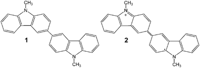
Supermolecular nanotubes and nanowires, which are formed by the self-assembly of low-molecular-mass organic molecules, are elegant architectures consisting of various intermolecular forces such as a CT interactions, π–π stacking, hydrogen bonding, van der Waals interactions, hydrophobic interactions, etc.1 These architectures can be modified into electric conductive architectures with various functions, which can be applied to components of organic molecular electronics by applying a doping treatment.2 In general, the nanotube and nanowire structures are prepared using an amphiphilic molecule, which has a rigid core and a long alkyl chain group. Bulky and complex molecules are mainly used as the starting material although they are called low-molecular-mass organic molecules. However, recently, the formations of the nano-fiber-structure, though not highly regular structures, from a low-molecular-mass organic gelator3 and mixed-valence tetrathiafulvalene,4 both of which have no long alkyl chain group, were reported. In particular, the latter was a nanofiber with an electric conductivity of about 10−2 S cm−1. In this communication, we report that highly-regular and electrically-conductive mixed-valence rectangular straight micro/nanotubes were formed using 9,9′-dimethyl-3,3′-bicarbazyl (1) and 9,9′-dimethyl-3,3′-bicarbazylium perchlorate (2), which were prepared by the electrochemical oxidation of 9-methylcarbazole. These well-ordered molecular arrays are expected to become important modules for the integration of molecular circuits, since the carbazole molecule, which is a building block of 1 and 2, is an attention-getting and important building block of new devices such as organic photovoltaic devices, secondary batteries, hole transport materials for organic light emitting diodes, organic field-effect transistors, transparent conductive materials, electrochromic devices, etc.5
Films composed of 1 and 2 were prepared on an indium-tin-oxide (ITO)-coated glass plate (10 Ω sq−1) by the controlled-potential electro-oxidation of 10 mM 9-methylcarbazole dissolved in a methanol solution containing tetrabutyl-ammonium perchlorate (TBA+ClO4−) under an N2 atmosphere. The working ITO electrode and the counter Pt plate were immersed in the main compartment of the electrolysis cell. The auxiliary compartment, which is separated from the main one by a sintered glass frit, had an immersed KCl agar bridge connected to the reference saturated calomel electrode (SCE). The electro-oxidation at + 1.1 V vs. SCE produced green-colored layers on the ITO. The electrical charge (Q) applied was typically 30 mC cm−2. The value of the applied potential (1.1 V) was determined by the linear sweep voltammetry of 9-methylcarbazol carried out before the above-mentioned experiment (Fig. S1, ESI†) (The electrode oxidation reaction of 9-methylcarbazol proceeded at a more anodic potential than 1.0 V vs. SCE, and a film with a more uniform morphology was formed at the lower potential). The identification of the chemical structure of these films (Figs. S2–S7, ESI†) was based on FT-IR, LDI-TOFMS, XPS, 1H NMR, ESR and UV-vis measurements. The molar ratio of 1 and 2 in the film was determined to be 1![[thin space (1/6-em)]](https://www.rsc.org/images/entities/char_2009.gif) :
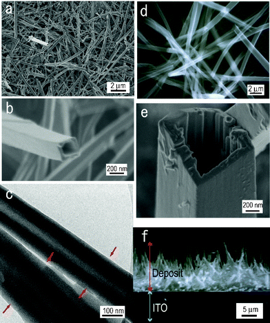
:![[thin space (1/6-em)]](https://www.rsc.org/images/entities/char_2009.gif) 1 by the XPS analysis. Part a in Fig. 1 shows the low-magnification FE-SEM image of the film prepared by the electrolytic oxidation of 9-methylcarbazol at 20 °C. Based on this image, it is understood that the film has a 1-dimensional (1D) structure consisting of a large number of fibers with diameters of 80–300 nm and a length of over 5 μm, and that the fiber has a rectangular straight tube structure, as shown in the magnified FE-SEM image (b) and TEM image (c) of a piece of these fibers. Part f shows the cross sectional SEM image of the film. Though most nanotubes seemed to be oriented diagonally to the substrate, some tubes were oriented perpendicularly to the substrate. Structures with similar sizes and shapes were obtained by the electrolytic oxidation at 10 °C and 40 °C. Parts d and e, respectively, show the SEM image and FE-SEM image of the tube structure obtained by the electrolytic oxidation at −10 °C. Thick and long 1D tubes with diameters of 400 nm to over 1 μm and a length of tens of microns were formed. Structures with similar sizes and shapes were obtained by the electrolytic oxidation at 0 °C and −20 °C. The difference in such shapes due to the difference in the electrolytic temperature is attributable to the difference in the rate of the electrolytic oxidation. In the case of −10 °C, an electrolysis time of 120 s was required in order to apply an electrical charge of 30 mC cm−2. This is about twice the time at 20 °C (62 s). The formation of the 1D rectangular straight micro/nanotube structure was examined using other solvents under the same experimental conditions as that in methanol. For acetonitrile, dichloromethane, and γ-butyrolactone, their electrolytic deposits dissolved and their films could not be formed. In the case of ethanol, the 1D tube structure was not observed though a film-shaped deposit was obtained.
1 by the XPS analysis. Part a in Fig. 1 shows the low-magnification FE-SEM image of the film prepared by the electrolytic oxidation of 9-methylcarbazol at 20 °C. Based on this image, it is understood that the film has a 1-dimensional (1D) structure consisting of a large number of fibers with diameters of 80–300 nm and a length of over 5 μm, and that the fiber has a rectangular straight tube structure, as shown in the magnified FE-SEM image (b) and TEM image (c) of a piece of these fibers. Part f shows the cross sectional SEM image of the film. Though most nanotubes seemed to be oriented diagonally to the substrate, some tubes were oriented perpendicularly to the substrate. Structures with similar sizes and shapes were obtained by the electrolytic oxidation at 10 °C and 40 °C. Parts d and e, respectively, show the SEM image and FE-SEM image of the tube structure obtained by the electrolytic oxidation at −10 °C. Thick and long 1D tubes with diameters of 400 nm to over 1 μm and a length of tens of microns were formed. Structures with similar sizes and shapes were obtained by the electrolytic oxidation at 0 °C and −20 °C. The difference in such shapes due to the difference in the electrolytic temperature is attributable to the difference in the rate of the electrolytic oxidation. In the case of −10 °C, an electrolysis time of 120 s was required in order to apply an electrical charge of 30 mC cm−2. This is about twice the time at 20 °C (62 s). The formation of the 1D rectangular straight micro/nanotube structure was examined using other solvents under the same experimental conditions as that in methanol. For acetonitrile, dichloromethane, and γ-butyrolactone, their electrolytic deposits dissolved and their films could not be formed. In the case of ethanol, the 1D tube structure was not observed though a film-shaped deposit was obtained.
 | ||
| Fig. 1 (a) FE-SEM image of the film on the ITO prepared by the electro-oxidation of 10 mM 9-methylcarbazole in methanol at 20 °C and 1.1 V vs. SCE (Q = 30 mC cm−2). (b) FE-SEM image of a single nanotube, the same sample as in (a). (c) TEM image of the nanotube prepared by the procedure in (a). (d) SEM image of the deposits prepared by the same method as in (a) except for the electrolysis temperature, −10 °C. (e) FE-SEM image of a single nanotube, the sample as in (d). (f) SEM image of the cross sectional view of the deposits prepared by the same method as in (a) except for Q, 100 mC cm−2. | ||
As already described, when a highly regular structure, such as the nanotube and nanowire, is formed, the combined action of various intermolecular forces and structural properties often becomes the driving force of the ordered structure formation. For instance, there are reports of a combination of π–π stacking interactions and van der Waals interactions between the alkyl chains,6 a combination of π–π stacking interactions and charge transfer interactions,4b a combination of π–π stacking interactions, charge transfer interactions and counter ion effect,4a a combination of π–π stacking interactions and secondary bonding forces,3a a combination of π–π stacking interactions and ion-ion interactions,1fetc. Taking into account these reports, the following three molecular structure characteristics can be enumerated as factors that generate the driving force for forming the 1D rectangular straight micro/nanotubes consisting of 1 and 2 (abbreviated as 1–2). The first structural characteristic is the π–π stacking interactions derived from the aromatic segment in 1–2, and these interactions are considered to play a significant role in forming the stacks of 1–2. The second structural characteristic is the existence of the methyl group, which is considered able to control the dissolution and association characteristics of 1–2. The third structural characteristic is the type of anion species, which is also supposed to influence the dissolution and association characteristics of 1–2. These three structural characteristic factors were examined in the following sections.
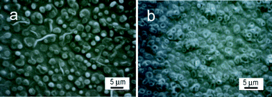
First of all, the electrolytic oxidations of 1-methylpyrrole and 1-methylindole, which are analogues of 9-methylcarbazol and have a shorter aromatic segment, were done in relation to the examination of the first factor. The films were deposited under the same electrolysis conditions for 9-methylcarbazole except for the electrolytic oxidation potential, the applied electrical charge and the raw material concentration (1.1 V and 200 mC cm−2 for 25 mM 1-methylpyrrole, 1.0 V and 70 mC cm−2 for 10 mM 1-methylindole). As for the electrolysis of the former, a granular structure or bowl-like structure was observed (Fig. 2a), and as for the electrolysis of the latter, a thick and short imperfect tube structure like barnacles was formed (Fig. 2b). These results suggest the longer the length of the aromatic segment, the more the π–π stacking interactions increase, and the more a regular structure is formed.
 | ||
| Fig. 2 SEM images of the deposits on the ITO prepared by the electro-oxidation of (a) 1-methylpyrrole and (b) 1-methylindole in methanol at 20 °C. | ||
Next, in order to study the second factor, the electrolytic oxidation of 9H-carbazole, 9-ethylcarbazole and 9-octylcarba-zole, which are analogues of 9-methylcarbazole and have a different length alkyl group bound to the N-position, was done. The films were deposited under the same electrolysis conditions as for the 9-methylcarbazole. However, a mixed solvent of methanol and water (1![[thin space (1/6-em)]](https://www.rsc.org/images/entities/char_2009.gif) :
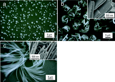
:![[thin space (1/6-em)]](https://www.rsc.org/images/entities/char_2009.gif) 3 vol. ratio) was used for the electro-oxidation of 9-ethylcarbazole because its electrolysis product dissolved in the solvent without water. As for 9H-carbazole, a structure that contained minute spherical particles deposited on a smooth film was obtained (Fig. 3a). As for 9-octylcarbazole, a structure like a rose flower was formed, and its structure was found to be an aggregate of plates based on the magnified image (upper right image of Fig. 3b). A fibrous structure shown in Fig. 3c was formed by the electrolytic oxidation of 9-ethylcarbazole. It was found that the fiber has a tubular structure based on the magnified FE-SEM image of the tip of the fiber (refer to the upper right image). The structural order of the product material increased in the order of: N–H (spheroidal) < N–C8H17 (tabular) < N–C2H5 (fibrous tube-shaped) < N–CH3 (straight tube-shaped). These results suggest that the substituent at the N-position controls the association and dissolution characteristics of the electrolytic products, and that it is also the factor of the regular structure formation.
3 vol. ratio) was used for the electro-oxidation of 9-ethylcarbazole because its electrolysis product dissolved in the solvent without water. As for 9H-carbazole, a structure that contained minute spherical particles deposited on a smooth film was obtained (Fig. 3a). As for 9-octylcarbazole, a structure like a rose flower was formed, and its structure was found to be an aggregate of plates based on the magnified image (upper right image of Fig. 3b). A fibrous structure shown in Fig. 3c was formed by the electrolytic oxidation of 9-ethylcarbazole. It was found that the fiber has a tubular structure based on the magnified FE-SEM image of the tip of the fiber (refer to the upper right image). The structural order of the product material increased in the order of: N–H (spheroidal) < N–C8H17 (tabular) < N–C2H5 (fibrous tube-shaped) < N–CH3 (straight tube-shaped). These results suggest that the substituent at the N-position controls the association and dissolution characteristics of the electrolytic products, and that it is also the factor of the regular structure formation.
 | ||
Fig. 3 SEM images of the deposits on the ITO prepared by the electro-oxidation of (a) 9H-carbazole, (b) 9-octylcarbazole, and (c) 9-ethylcarbazole at 20 °C. Solvent: (a) and (b), methanol; (c), mixed solvent of methanol and water (1![[thin space (1/6-em)]](https://www.rsc.org/images/entities/char_2009.gif) : :![[thin space (1/6-em)]](https://www.rsc.org/images/entities/char_2009.gif) 3 vol. ratio). The figures inserted in parts b and c show the corresponding FE-SEM images. 3 vol. ratio). The figures inserted in parts b and c show the corresponding FE-SEM images. | ||
Next, the electrolytic oxidation of 9-methylcarbazole was done using TBA+BF4−, TBA+PF6− and Li+ClO4− as supporting electrolytes in order to examine the third factor. The film was deposited under the same electrolysis conditions when TBA+ClO4− was used. When the electrolysis was done using TBA+BF4− at temperatures of 20 °C and −10 °C, similar nanotubes to those obtained by electrolysis using TBA+ClO4− at 20 °C were obtained. On the other hand, when TBA+PF6− was used, though the nanotubes were also produced at each electrolysis temperature, the produced nanotubes interlocked with each other, and a structure similar to the nanotubes embedded in a flat film was obtained. When Li+ClO4− was used at each electrolysis temperature, the same structure as when using TBA+ClO4− was formed (Fig. S8, ESI†). Based on these results, it can be concluded that the driving force of the 1–2 nanotube formation is the π–π stacking interactions and the structural characteristic properties of the substituent at the N-position and counter anionic species in 2.
The electric conductivity of a single 1–2 nanotube measured in a two terminal configuration7 (Fig. S9, ESI†) was 2.3 × 10⁻⁵ S cm−1. Considering that the value involves the contribution from the contact resistance between the nanotube and electrodes, it can be considered electrically conductive.
The organic 1D rectangular straight micro/nanotube obtained in this study can be applied to the development of various energy and image devices already described. We are currently exploring the mechanism of the 1–2 nanotube formation (Fig. S10, ESI†), and have started to study a chemical mass production method of nanotubes and the development of their applications. The results will be separately reported.
Acknowledgements
The authors thank Prof. H. Seki and Dr M. Imanari for help with the 1H NMR, FD-MS, and ESR analyses. Our thanks are extended to JEOL for the ESR measurements. This work was partially supported by a Grant-in-Aid for Scientific Research (C) from JSPS to K. H. (21605003).References
- (a) M. Hasegawa and M. Iyoda, Chem. Soc. Rev., 2010, 39, 2420 RSC; (b) L. Zang, Y. Che and J. S. Moore, Acc. Chem. Res., 1997, 30, 402 CrossRef; (c) P. Batail, Chem. Rev., 2004, 104, 4887 CrossRef CAS; (d) K. Balakrishnan, A. Datar, W. Zhang, X. Yang, T. Naddo, J. Huang, J. Zuo, M. Yen, J. S. Moore and L. Zang, J. Am. Chem. Soc., 2006, 128, 6576 CrossRef CAS; (e) T. Naddo, Y. Che, W. Zhang, K. Balakrishnan, X. Yang, M. Yen, J. Zhao, J. S. Moore and L. Ling Zang, J. Am. Chem. Soc., 2007, 129, 6978 CrossRef CAS; (f) B. E. Hamaoui, L. Zhi, W. Pisula, U. Kolb, J. Wu and K. Müllen, Chem. Commun., 2007, 2384 RSC.
- (a) J. Kong, N. R. Franklin, C. Zhou, M. G. Chapline, S. Peng, K. Cho and H. Dai, Science, 2000, 287, 622 CrossRef CAS; (b) J. P. Hill, W. Jin, A. Kosaka, T. Fukushima, H. Ichihara, T. Shimomura, K. Ito, T. Hashizume, N. Ishii and T. Aida, Science, 2004, 304, 1481 CrossRef CAS; (c) J. Sly, P. Kasák, E. Gomar-Nadal, C. Rovira, L. Górriz, P. Thordarson, D. B. Amabilino, A. E. Rowan and R. J. M. Nolte, Chem. Commun., 2005, 1255 RSC; (d) K. Nakano, M. Nishimura, T. Tamachi, Y. Kuwatani, H. Miyasaka, T. Nishinaga and M. Iyoda, J. Am. Chem. Soc., 2006, 128, 16740 CrossRef; (e) M. Williams-Harry, A. Bhaskar, G. Ramakrishna, T. Goodson, M. Imamura, A. Mawatani, K. Nakano, H. Enozawa, T. Nishinaga and M. Iyoda, J. Am. Chem. Soc., 2008, 130, 3252 CrossRef CAS; (f) J. Puigmarí-Luís, E. Laukhina, Á. P. del Pino, J. Vidal-Gancedo, C. Rovira and D. B. Amabilino, Angew. Chem., Int. Ed., 2007, 46, 238 CrossRef; (g) D. Canevet, M. Salle, G. Zhang, D. Zhang and D. Zhu, Chem. Commun., 2009, 2245 RSC.
- (a) B.-K. An, D.-S. Lee, J.-S. Lee, Y.-S. Park, H.-S. Song and S. Y. Park, J. Am. Chem. Soc., 2004, 126, 10232 CrossRef CAS; (b) B.-K. An, S. H. Gihm, J. W. Chung, C. R. Park, S.-K. Kwon and S. Y. Park, J. Am. Chem. Soc., 2009, 131, 3950 CrossRef CAS.
- (a) K. Tanaka, T. Kunita, F. Ishiguro, K. Naka and Y. Chujo, Langmuir, 2009, 25, 6929 CrossRef CAS; (b) K. Naka, D. Ando, X. Wang and Y. Chujo, Langmuir, 2007, 23, 3450 CrossRef CAS.
- (a) J.-F. Martin, M. Leclerc, D. Adés and A. Siove, Macromol. Rapid Commun., 2005, 26, 761 CrossRef; (b) K. Hoshino, N. Yazawa, Y. Tanaka, T. Chiba, T. Izumizawa and M. Kubo, ACS Appl. Mater. Interfaces, 2010, 2, 413 CrossRef CAS.
- Y. Homma, E. Isomura, H. Enozawa, M. Hasegawa, M. Takase, T. Nishinaga and M. Iyoda, Tetrahedron Lett., 2010, 51, 679 CrossRef.
- (a) G. A. O'Brien, A. J. Quinn, D. A. Tanner and G. Redmond, Adv. Mater., 2006, 18, 2379 CrossRef CAS; (b) Q. Tang, L. Jiang, Y. Tong, H. Li, Y. Liu, Z. Wang, W. Hu, Y. Liu and D. Zhu, Adv. Mater., 2008, 20, 2947 CrossRef CAS.
Footnote |
| † Electronic Supplementary Information (ESI) available: Experimental details and characterization data for 1–2. See DOI: 10.1039/c2ra01029a/ |
| This journal is © The Royal Society of Chemistry 2012 |

