Effects of VC-LiBOB binary additives on SEI formation in ionic liquid–organic composite electrolyte†
Yongxin
An
ab,
Pengjian
Zuo
a,
Chunyu
Du
a,
Yulin
Ma
a,
Xinqun
Cheng
a,
Jianyi
Lin
*b and
Geping
Yin
*a
aState Key Laboratory of Urban Water Resource and Environment, School of Chemical Engineering and Technology Harbin Institute of Technology, NO.92 West-dazhi street, Harbin, China. E-mail: yingeping2006@yahoo.com.cn; Fax: (+86)-0451-86413707
bInstitute of Chemical and Engineering Sciences, Agency for Science, Technology and Research, Singapore. E-mail: Lin_jianyi@ICES.A-star.edu.sg
First published on 16th March 2012
Abstract
A safe electrolyte based on an ionic liquid–organic composite with binary additives was prepared. The stable solid electrolyte interphase (SEI) forms on the surface of a carbon anode by addition of vinylene carbonate (VC) and lithium bis(oxalato) borate (LiBOB) binary additives in ionic liquid–organic electrolyte mixture. The stable SEI effectively prevents the co-intercalation of PP13+ cations, thus leading to an obvious improvement in the performance of the cell.
Introduction
Li-ion batteries are widely used as the power source for consumer electronics, such as mobile phones and portable computers due to their high voltage and high energy density.1–3 Especially, they attract increasing attention for application in electric and hybrid electric vehicles because they are light, compact, relatively cheap and safe.4,5 However, Li-ion batteries have several drawbacks, including thermal runway which may be caused by the burning of commonly used LiPF6–organic carbonate solution electrolyte and capacity loss caused by the reactions of the electrolyte with the surface of electrode materials. To improve the safety and stability of Li-ion batteries, the development of more suitable electrolytes and additives which can stabilize the electrolyte–electrode interfaces is underway.6,7 Ionic liquids (ILs) as an emerging class of electrolytes have been widely investigated in recent years. ILs are non-volatile, non-flammable, highly conductive, environmentally compatible and can safely operate in a wide temperature range. This unique combination of favorable properties makes ILs very promising materials as stable and safe electrolyte media in lithium batteries.8–13 Ionic liquids consisting of imidazolium-based cations have been widely studied because of their low viscosity and high ionic conductivity. For example the ionic conductivity of 1-ethyl-3-methylimidazolium bis(trifluoromethylsulfonyl)imide (EMI-TFSI) is as high as 10−2 S cm−1 at room temperature.14,15 However these ILs cannot be commercialized due to a poor cathodic stability limit associated with the reactivity of imidazolium-based cations with low voltage anode materials such as lithium or graphite. Thus one of the challenges is to widen the cathodic stability window of the ILs to remove the safety hazards. Recently, some useful results were obtained by the optimization of the IL cation with safer and more reliable properties, for example, pyrrolidinium (PY) and piperidinium (PP) cations which have lower stable reductive potential (−0.3V vs. Li/Li+) than that (1.5 V vs. Li/Li+) of a typical imidazolium family16,17 (the structure of the IL and additive is shown in Fig. S1 in the ESI†). However, the high viscosity of these ILs results in a lower ion conductivity than conventional organic electrolyte. Moreover, the surface electrolyte interface (SEI) formed with ILs composed of PP (or PY) cation and TFSI anion cannot passivate the surface of a graphite-based anode. Hence further efforts should be devoted to solve these problems. Recent reports have shown that the addition of an appropriate organic electrolyte in the ionic liquid can gain better performance without losing safety.18,19Vinylene carbonate (VC) and lithium bis(oxalato) borate (LiBOB) are promising additives for the SEI film formation, which can passivate the surface of a graphite anode effectively with an improved capacity retention, especially in propylene carbonate (PC) and ILs20,21 (the mechanism and SEM images of additive forming SEI are shown in Fig. S2 and Fig. S3 in the ESI†). VC has been a widely used additive for SEI formation in the past decade, and cells using VC addition can get better cycle performance and coulombic efficency,22,23 but the cell suffers from largely irreversible capacity loss during the 1st cycle. LiBOB as a promising and advantageous lithium salt for lithium ion batteries has many advantages compared with LiPF6, including superior thermal stability, increased safety and high temperature cycle performance of the cell.24 Furthermore, the voltage of the LiBOB formed SEI on the carbon anode during the first cycle is 1.75 V,25,26 higher than that of the VC formed SEI (~1 V), that can partly restrain the VC decomposition and thus improve the 1st coulombic efficiency of the cell (the CV and cycle plots of the Li/C cell using only VC-containing mixed electrolyte are shown in Fig. S4 in the ESI†). The SEI formed with the binary additives showed better performance than that with a single additive.27
In this paper, we proposed a mixed electrolyte, containing 50 vol% ionic liquid (i.e. PP13-TFSI), 45 vol% organic electrolyte (i.e. 1 M LiPF6 in 1![[thin space (1/6-em)]](https://www.rsc.org/images/entities/char_2009.gif) :
:![[thin space (1/6-em)]](https://www.rsc.org/images/entities/char_2009.gif) 1 v/v ethylene carbonate/diethyl carbonate), 5 vol% VC, and 2 wt% LiBOB (i.e. 2% mass of the solvents). VC and LiBOB were added as binary additives to facilitate the SEI formation on the anode while the organic solution electrolyte was added to reduce the IL's viscosity and to increase their conductivity. The use of IL was shown to improve the non-flammability and reliability of the system. The SEI formation was characterized and confirmed by cyclic voltammetry, impedance electrochemical measurements, scanning electron microscope (SEM) and X-ray photoelectron spectroscopy (XPS).
1 v/v ethylene carbonate/diethyl carbonate), 5 vol% VC, and 2 wt% LiBOB (i.e. 2% mass of the solvents). VC and LiBOB were added as binary additives to facilitate the SEI formation on the anode while the organic solution electrolyte was added to reduce the IL's viscosity and to increase their conductivity. The use of IL was shown to improve the non-flammability and reliability of the system. The SEI formation was characterized and confirmed by cyclic voltammetry, impedance electrochemical measurements, scanning electron microscope (SEM) and X-ray photoelectron spectroscopy (XPS).
Results and discussion
Fig. 1a shows the thermogravimetric curves of different electrolytes. There is only a little weight loss in pure ionic liquid PP13-TFSI below 400 °C, which confirms the good thermal stability. 1 M LiPF6/EC-DEC electrolyte is thermally unstable, with 90% weight loss being found below 250 °C. The poor thermal stability of the conventional organic electrolytes may cause flaming, smoking or thermal runaway of the Li ion cells. When adding 50 vol% IL to the organic electrolyte, the thermal stability of organic electrolyte is well improved.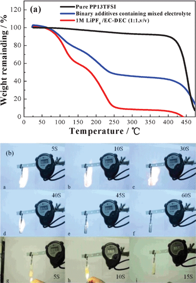 | ||
Fig. 1 (a) TG curves of different electrolytes, (b) burning tests of organic electrolyte 1 M LiPF6 in EC–DEC (1![[thin space (1/6-em)]](https://www.rsc.org/images/entities/char_2009.gif) : :![[thin space (1/6-em)]](https://www.rsc.org/images/entities/char_2009.gif) 1, v/v) (from a to f), and ionic liquid–organic electrolyte–binary-additives composite, i.e. a mixture of PP13TFSI + 1 M LiPF6 in ethylene carbonate–diethyl carbonate (EC–DEC) (1 1, v/v) (from a to f), and ionic liquid–organic electrolyte–binary-additives composite, i.e. a mixture of PP13TFSI + 1 M LiPF6 in ethylene carbonate–diethyl carbonate (EC–DEC) (1![[thin space (1/6-em)]](https://www.rsc.org/images/entities/char_2009.gif) : :![[thin space (1/6-em)]](https://www.rsc.org/images/entities/char_2009.gif) 1, v/v) + binary additives (from g to i). 1, v/v) + binary additives (from g to i). | ||
Fig. 1b demonstrates the burning of the electrolytes. The traditional organic electrolyte, i.e.1 M LiPF6 in EC–DEC (1![[thin space (1/6-em)]](https://www.rsc.org/images/entities/char_2009.gif) :
:![[thin space (1/6-em)]](https://www.rsc.org/images/entities/char_2009.gif) 1, v/v), was ignited instantaneously, caught fire, and kept the flame for more than 60 s. In contrast, the mixed IL–electrolyte–additives composite electrolyte, i.e. PP13-TFSI + 1 M LiPF6 in EC–DEC (1
1, v/v), was ignited instantaneously, caught fire, and kept the flame for more than 60 s. In contrast, the mixed IL–electrolyte–additives composite electrolyte, i.e. PP13-TFSI + 1 M LiPF6 in EC–DEC (1![[thin space (1/6-em)]](https://www.rsc.org/images/entities/char_2009.gif) :
:![[thin space (1/6-em)]](https://www.rsc.org/images/entities/char_2009.gif) 1, v/v) + binary additives (VC + LiBOB), did not ignite during the burning test. This is a very important characteristic for battery safety and the ionic liquid played an important role in the non-flaming of the mixed electrolyte.
1, v/v) + binary additives (VC + LiBOB), did not ignite during the burning test. This is a very important characteristic for battery safety and the ionic liquid played an important role in the non-flaming of the mixed electrolyte.
The SEI formation is proven by the cyclic voltammograms of the hard-carbon/graphite-composite//Li cell with two different electrolytes in Fig. 2. As expected, the additive-free system in Fig. 2a shows a strong irreversible cathodic peak at ~0.25 V, which is attributed to the insertion of ionic liquid cation PP13+ to the carbon electrode.
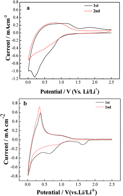 | ||
| Fig. 2 Cyclic voltammogram plots of a hard-carbon/graphite composite//Li cell using (a) the additive-free electrolyte, and (b) the binary-additives-containing mixed electrolyte at a scan rate 0.02 mV s−1. | ||
In contrast, in VC-LiBOB containing electrolyte (Fig. 2b), the cathodic peaks are observed at 0.8 V and 1.75 V in the first cycle, corresponding to the decomposition of VC and LiBOB respectively to form SEI film. The clear anodic peak is obtained at ~0.25 V, which is the potential of Li+ extraction from active materials. Therefore, a reversible lithium insertion–extraction couple is proposed in the mixed electrolyte containing binary additives.
The electrochemical impedance spectroscopy (ESI) is widely used to investigate electrolyte–electrode interactions, such as the electrochemical lithium intercalation reaction in carbonaceous material within the carbonate electrolyte and the subsequent formation of SEI films. The Nyquist spectra of the Li//hard-carbon/graphite composition cells using mixed electrolyte without (a) and with (b) VC-LiBOB binary additives are shown in Fig. 3. The inset in Fig. 3a plots the equivalent circuit of the impedance data measured for the Li//carbon cells. Here Re represents the Ohmic resistance which includes electrolyte solution resistance, electric contacts resistance and ion conductive resistance and its value is obtained from the intercept (close to the origin of the coordinate) at the X-axis in high angular frequency. The semicircle in the high frequency range corresponds to the surface film resistance (Rf) while the semicircle in the middle frequency range reflects the charge transfer resistance (Rct). The sloping line in the lower frequency represents lithium-ion diffusion resistance in bulk electrode.28,29
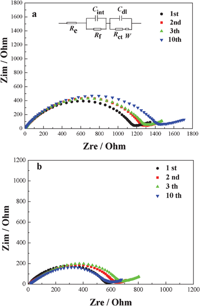 | ||
| Fig. 3 Impedance spectra of the Li//hard-carbon/graphite composition half-cells using mixed electrolyte without (a) and with (b) binary additives recorded at 0.01 V. | ||
Table 1 gives the Rf values of first 10 cycles in different electrolyte-system by computer simulations (Z-Plot).
| Cycle number | Impedance (Ω) for the cell without additives in the electrolyte | Impedance (Ω) for the cell with binary additive in the electrolyte |
|---|---|---|
| 1 | 113.1 Ω | 84.8 Ω |
| 2 | 120.7 Ω | 72.4 Ω |
| 3 | 145.9 Ω | 69.7 Ω |
| 10 | 163.9 Ω | 68.4 Ω |
The Rf value of the cell using mixed electrolyte without additive increases from 113.1 Ω to 163.9 Ω after 10 cycles, this implies that the SEI film is unstable with the electrolyte without additives, which leads to the continuous reaction between the electrode and electrolyte. The Rf value of the cell with the binary additives decreases from 84.8 Ω to 69.7 Ω after 3 cycles, then stabilize to 68.4 Ω after 10 cycles. This is attributed to the formation of a stable SEI of higher conductivity, which effectively reduces the interface resistance between the electrolytes and electrode.
Fig. 4 shows the surface morphologies of the hard-carbon/graphite composite electrode after 1 cycle in PP13-TFSI/1M-LiPF6/EC-DEC mixed electrolyte without (a, b) and with binary additives (c, d). As can be seen, the electrode surface without additives is covered with a poor SEI film with exfoliation, which results in an increase in the Rf and Rct values of the cell. The electrode using the mixed electrolyte containing binary additives is covered with a continuous and conformal film, which is significantly different from the electrode without additives. These results confirm that addition of 2 wt% LiBOB and 5 vol% VC formed compact and stable SEI film. The SEI film prevents the surface of electrode from the direct contact with the electrolyte solution and the co-intercalation of PP13+ during the course of charge–discharge cycles.
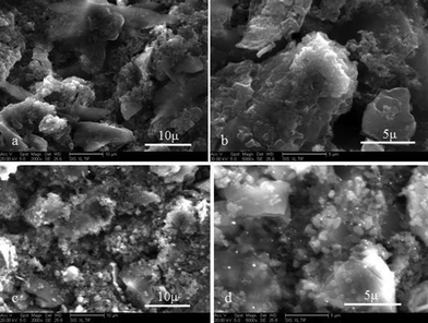 | ||
| Fig. 4 SEM images of the hard-carbon/graphite anode using mixed electrolyte without (a, b) and with binary additives (c, d) after 1 cycle. The images a and c are obtained from the pristine electrode while b and d are from the electrodes after 1 charge–discharge cycle. | ||
To understand the effects of binary additives on the formation of SEI film, the surface components of the electrode after 1 cycle were investigated by XPS.30,31
Fig. 5 presents the XPS spectra of the surface layers formed in different electrolytes. The C1s spectra in Fig. 5(a, b) are for the anode materials using the electrolyte without and with the additives respectively. The C 1s peaks between 282 and 292 eV were deconvoluted to three components. The peak at 284.7 eV is assigned to bulk graphite, while the peak at 286 eV is assigned to the carbon with an ether linkage (from the polymeric decomposition products), and the peak at 289 eV is assigned to carbonyl moieties (semicarbonate). When LiBOB and VC are present in the mixed electrolyte, the C1s spectrum in Fig. 5b (with binary additives) consists of twin peaks (first and third) of comparable abundance, with the second peak corresponding to a polyether-like carbon shouldered under the first peak, which is due to the participation of VC and LiBOB in SEI formation.32 Without the VC additive the third C1s component is rather weak due to little interaction with conventional carbonates.
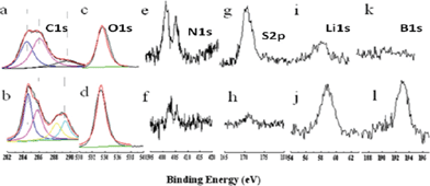 | ||
| Fig. 5 XPS spectra of C1s, O1s, N1s, S2p, Li1s B1s for anode samples that have been cycled in mixed electrolyte without (a, c, e, g, i, k) and with binary additives (b, d, f, h, j, l), respectively. | ||
In addition to the XPS C1s spectra, the most obvious difference between mixed electrolytes with/without binary additives was noted in S 2p (Fig. 5e) and N 1s (Fig. 5f) spectra. In a mixed electrolyte without additives, the S 2p and N 1s signals show a high intensity, while they are rather weak in the spectra with the binary additives. Ionic liquid anion TFSI− is the only source of elemental sulphur and nitrogen, the serious decomposition and co-intercalation of ionic liquid was thought to occur in mixed electrolyte without additives. In contrast, very little decomposition of the ionic liquid was detected in binary additives containing the mixed electrolyte.
Pronounced B 1s peak at 193 eV and Li 1s at 59 eV appear at SEI layers formed in the mixed electrolyte containing LiBOB (Fig. 5j and 5l). They are not evident or not observable in the mixed electrolyte without additives, confirming that the additive LiBOB indeed took part in the formation of a SEI film.
The surface elemental concentrations of SEI with different electrolytes are collected in Table 2 for comparison. The concentration of C, O, and Li is higher in mixed electrolyte containing binary additives than the additive-free sample while the concentration of F, N and S is lower in mixed electrolyte with binary additives than the additive-free sample, both of which have positive effects on the SEI layer.
| Entry | C | O | F | N | S | Li | B |
|---|---|---|---|---|---|---|---|
| a The mixed electrolyte without additive. b The mixed electrolyte containing 2 wt% LiBOB. c The mixed electrolyte containing 5 vol% VC. d The mixed electrolyte containing 2 wt% LiBOB +5 vol%VC. | |||||||
| 1a | 29.45 | 28.26 | 17.52 | 5.37 | 3.29 | 10.83 | 0 |
| 2b | 29.44 | 39.47 | 9.89 | 2.44 | 1.66 | 14.11 | 2.99 |
| 3c | 37.85 | 38.25 | 8.76 | 1.26 | 0.96 | 12.66 | 0 |
| 4d | 34.04 | 43.73 | 3.04 | 0.69 | 0.22 | 15.86 | 2.17 |
The cycle performance of hard-carbon/graphite//Li cells with/without the binary additives at different current rates are shown in Fig. 6a. It can be seen that capacity of the cell using the binary additives in the mixed electrolyte is about 300 mA h g−1 at a discharge rate of 0.1 C (~0.03 mA cm−2), higher than 250 mA h g−1 for the cell without the additives. When the discharge rates are increased from 0.1 C to 0.2 C, the capacity of the cell containing binary additives decreases from 305 mA h g−1(0.1 C), 275 mA h g−1 (0.15 C) to 200 mA h g−1 (0.2 C). The cell without the additive decreased from 250 mA h g−1(0.1 C), 200 mA h g−1(0.15 C) to 150 mA h g−1 (0.2 C). Both voltage and the capacity of the cell with binary additives are found to be kept at relatively higher values than additive-free cells. At 0.2 C rate, the battery containing the binary additives keeps 67.8% of discharge capacity of 0.1 C, while the cell using the additive-free mixed electrolyte is only 59% of the capacity retention of discharge rate 0.1 C. (The voltage–capacity plots of the cell using mixed electrolyte with/without binary additive are shown in Fig. S5 in the ESI.†) The coulomb efficiency of the 2nd cycle is 98.3% that of the first cycle. The sufficiently small irreversibility is observed for the cell with binary additive, even after 20 cycles. This effect is attributed to the SEI formed by the binary additives, which stabilized the structure of the anode during charge–discharge cycles.
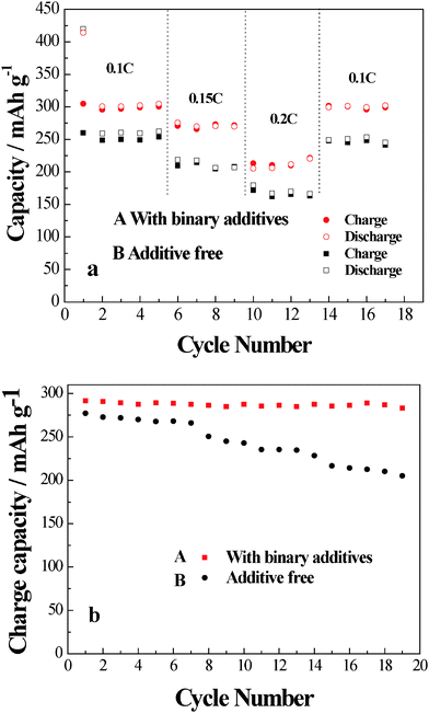 | ||
| Fig. 6 (a) The cycle performance of hard carbon-graphite/Li cells using mixed electrolyte with (A)/without (B) binary additives at different charge–discharge rate. (b) The cycle performance of hard carbon-graphite/Li cells using mixed electrolyte with (A)/without (B) binary additives at 50 °C. | ||
It can be seen in Fig. 6b that the reversible capacity shows a little reduction with increasing the cycle number and the retention of rate capacity at 50 °C is improved greatly in the mixed electrolyte with binary additives. The rate capacity of the cell with binary additives loses only 2.8% capacity in 20 cycles at 0.1 C charge–discharge rate, while the cell with the additive-free mixed electrolyte loses 26.3% capacity. This result clearly shows the excellent cycle performance of the cell using the binary additive containing mixed electrolyte at 50 °C. The improvement of the capacity retention may be related to the stable SEI film formed by binary additives.
It is worth mentioning that the Li/LiFePO4 cell using mixed electrolyte containing the binary additive also showed the acceptable reversible capacity and coulombic efficiency (the cycle performance of the Li/LiFePO4 cell using a binary additive is shown in Fig. S6 in the ESI†).
Experimental
Thermal and burning tests
The thermal properties of the electrolyte were measured with thermogravimetric analysis instrument (TG, Netzsch ST447F5) from 25 to 400 °C at the rate of 5 °C min−1 under argon atmosphere.For the burning tests, fiberglass wicks (2 cm × 4 cm) were first immersed in the electrolyte, absorbing about 1 g of electrolyte. A lighter was used to ignite one end of the fiber. After 10 s, the lighter was removed from the underneath of the fiberglass wicks, the electrolyte was judged to be nonflammable if the electrolyte was never ignited during the testing, or if the ignition of electrolyte ceased when the lighter was removed. Each electrolyte was tested three times.
Cell preparation and electrochemical measurements
As an anode material, hard carbon has many merits (including good rate capability and safety). Especially, hard carbon is stable during charge–discharge cycling in PC and IL-based electrolytes. But hard carbon suffers from quick capacity fading, especially large irreversible capacity loss during the first cycle, as compared to graphite.In this paper, in order to find compatible anode materials with ionic liquids, we used hard-carbon/graphite composite as active materials. Hard-carbon/graphite composite was prepared by mechanically mixing the hard carbon (Kureha Corp, Japan) with graphite (MAGD, Hitachi chemical) at a mass ratio of 1![[thin space (1/6-em)]](https://www.rsc.org/images/entities/char_2009.gif) :
:![[thin space (1/6-em)]](https://www.rsc.org/images/entities/char_2009.gif) 2 in a planetary ball mill.
2 in a planetary ball mill.
The electrodes of the anode were prepared by casting a slurry containing 80 wt% active materials, 10 wt% acetylene black (AB) and 10 wt% polyvinylydene fluoride (PVDF) on copper foil and dried at 120 °C for 10 h under vacuum, and the electrode was punched into disks with an area of 1.54 cm2 and active material mass of ∼1.5 mg, then they were assembled into a Li//hard-carbon/graphite composition coin cell. The cell was subjected to battery tests (charged–discharged between 1.5 and 0.01 V) at room temperature and 50 °C.
Cyclic voltammetry (CV) was measured on a half cell of Li//electrolytes//hard-carbon/graphite composite cell at a rate of 2 mV s−1 between 0.01 V and 1.5 V. Electrochemical impedance spectroscopy was also measured with the same cell mentioned above at 0.0 1 V (0.01 Hz–105 Hz) by an electrochemical analyzer (CHI604B).
Micrograph and surface characterization techniques
The surface morphology of the electrodes was observed with scanning electron microscopy (Hitachi S-4700). For photoelectron spectroscopy analysis the electrodes were taken out and washed twice with dimethyl carbonate (DMC) solvent and then dried under vacuum overnight. A vacuum sample transporter was used to load the dried samples into the XPS sample chamber from glove box atmosphere. Surface analysis was then conducted on those electrodes with a PHI 5800 XPS system, where a Al Kα excitation source was used. The resolution of the measurement generally falls within 0.3 eV and the elemental carbon peak at 284.4 eV was used as the internal reference to calibrate the energy position.Conclusions
In summary, binary additives (LiBOB and VC) have an important influence on electrochemical properties of the cell using the ionic liquid (PP13-TFSI) and 1 M LiPF6/EC–DEC mixed electrolyte. The formation of stable SEI film by adding the binary additives (LiBOB and VC) was confirmed by cyclic voltammetry, impedance electrochemical measurements, SEM and XPS. The reversible capacity and capacity retention of the Li//hard-carbon/graphite composition cell are improved at room temperature and 50 °C due to the binary additives. The high thermal stability and non-flammability of the cells with binary additives were also confirmed by TGA and burning tests.Acknowledgements
The authors would like to thank the anonymous reviewers and the finance support from the 863 Foundation of China (No.2009AA11A105).References
- T. Ishizu, T. Lojima, T. horiba and M. Yoshikawa, Shin-Kobe Technical Report, 2007, 17, 16–20 Search PubMed.
- M. Armand and J. M. Tarascon, Nature, 2008, 451, 652–657 CrossRef CAS.
- C. Daniel, JOM, 2008, 60(9), 43–48 CrossRef CAS.
- K. Smith and C. Y. Wang, J. Power Sources, 2006, 160, 662–673 CrossRef CAS.
- W. Lu, A. Jansen, D. Dees, P. Nelson, N. R. Veselka and G. Henriksen, J. Power Sources, 2011, 196, 1537–1540 CrossRef CAS.
- S. S. Zhang, J. Power Sources, 2006, 162, 1379–1394 CrossRef CAS.
- F. M. Wang, H. M. Cheng, H. C. Wu, S. Y. Chu, C. S. Cheng and C. R. Yang, Electrochim. Acta, 2009, 54, 3344–3351 CrossRef CAS.
- A. Fernicola, F. Croce, B. Scrosati, T. Watanabe and H. Ohno, J. Power Sources, 2007, 174, 342–348 CrossRef CAS.
- M. Galinski, A. Lewandowski and I. Stepniak, Electrochimica. Acta, 2006, 51 Search PubMed.
- M. Armand, F. Enders, D. R MacFarlane, H. Ohno and B. Scrosati, Nat. Mater., 2009, 8, 621–628 CrossRef CAS.
- P. G. Jessop, Green Chem., 2011, 13, 1319 Search PubMed.
- T. Welton, Green Chem., 2011, 13, 225 RSC.
- P. S. Kulkarni and C. A. M. Afonso, Green Chem., 2010, 12, 1139–1149 RSC.
- S. Seki, Y. Kobayashi, H. Miyashiro, Y. Ohno, A. Usami, Y. Mita, N. Kihira, M. Watanabe and N. Terada, J. Phys. Chem. B, 2006, 110, 10228–10230 CrossRef CAS.
- M. Holzapfel, C. Jost, A. Prodi-Schwab, F. Krumeich, A. Wursig, H. Buqa and P. Novak, Carbon, 2005, 43, 1488 CrossRef CAS.
- H. Sakaebe and H. Matsumoto, Electrochem. Commun., 2003, 5, 594–598 CrossRef CAS.
- H. Matsumoto, H. Sakaebe and K. Tatsumi, J. Power Sources, 2005, 146, 45–50 CrossRef CAS.
- A. Guerfi, M. Dontigny, P. Charest, M. Petitclerc, M. Lagace, A. Vigh and K. Zaghib, J. Power Sources, 2010, 195, 845–852 CrossRef CAS.
- H. Nakagawa, Y. Fujino, S. Kozono, Y. Katayama, T. Nukudaa, H. Sakaebe, H. Matsumoto and K. Tatsumi, J. Power Sources, 2007, 174, 1021–1026 CrossRef CAS.
- Z. Chen, W. Q. Lu, J. Liu and K. Amine, Electrochim. Acta, 2006, 51, 3322–3326 CrossRef CAS.
- W. Q. Lu, Z. H. Chen and H. Joachin, J. Power Sources, 2007, 163, 1074–1079 CrossRef CAS.
- M. Holzapfel, C. Jost and P. Novak, Chem. Commun., 2004, 2098–2099 RSC.
- T. Sato, T. Maruo, S. Marukane and K. Takagi, J. Power Sources, 2004, 138(1–2), 253–261 CrossRef CAS.
- U. Lischka, U. Wietelmann and M. W. German, Pat, DE, 1999, 19829030C1 Search PubMed.
- Y. X. An, P. J. Zuo, X. Q. Cheng, L. X. Liao and G. P. Yin, Electrochim. Acta, 2011, 56, 4841–4848 CrossRef CAS.
- M. S. Ding, K. Xu and T. R. Jow, J. Electrochem. Soc., 2005, 152(1), A132–A140 CrossRef CAS.
- S. Santee, A. Xiao, L. Yang, J. Gnanara and B. L. Lucht, J. Power Sources, 2009, 194, 1053–1060 CrossRef CAS.
- M. Itagaki, S. Yotsuda, N. Kobari, N. Koabari, K. watanabe, S. Kinoshita and M. Ue, Electrochim. Acta, 2006, 51, 1629–1635 CrossRef CAS.
- J. Y. Song, H. H. Lee and Y. Y. Wang, J. Power Sources, 2002, 111, 255–267 CrossRef CAS.
- K. Xu, U. Lee and S. S. Zhang, Electrochem. Solid-State Lett, 2003, 6, A144–A148 CrossRef CAS.
- J. WChoia, G. Cheruvallya and D. S. Kim, J. Power Sources, 2008, 183, 441 CrossRef.
- L. W. Zhao, J. I. Yamaki and M. Egashira, J. Power Sources, 2007, 174, 352–358 CrossRef CAS.
Footnote |
| † Electronic Supplementary Information (ESI) available: The structure of IL and additives, mechanism of VC and LiBOB forming SEI, the first charge–discharge plots of cells, and the cycle performance of Li/LiFePO4 using the binary additives containing mixed electrolyte. See DOI: 10.1039/c2ra01040b/ |
| This journal is © The Royal Society of Chemistry 2012 |
