A new energy conversion technology joining electrochemical and physical principles†
Bin
Zhu
ab,
Rizwan
Raza
ac,
Qinghua
Liu
a,
Haiying
Qin
a,
Zhigang
Zhu
a,
Liangdong
Fan
a,
Manish
Singh
a and
Peter
Lund
b
aDepartment of Energy Technology, Royal Institute of Technology, KTH 10044, Stockholm, Sweden
bDepartment of Applied Physics, Aalto University, 00076 Aalto, Finland
cDepartment of Physics, COMSATS Institute of Information Technology, Lahore 54000, Pakistan
First published on 3rd May 2012
Abstract
We report a new energy conversion technology joining electrochemical and physical principles. This technology can realize the fuel cell function but built on a different scientific principle. The device consists of a single component which is a homogenous mixture of ceria composite with semiconducting materials, e.g. LiNiCuZn-based oxides. The test devices with hydrogen and air operation delivered a power density of 760 mW cm−2 at 550 °C. The device has demonstrated a multi-fuel flexibility and direct alcohol and biogas operations have delivered 300–500 mW cm−2 at the same temperature. Device physics reveal a key principle similar to solar cells realizing the function based on an effective separation of electronic and ionic conductions and phases within the single-component. The component material multi-functionalities: ion and semi-conductions and bi-catalysis to H2 or alcohol (methanol and ethanol) and air (O2) enable this device realized as a fuel cell.
Energy conversion technologies are one of the key issues for this century.1 Based on our latest invention on fuel cells (FC) using only a single-component which can function as electrodes and the electrolyte simultaneously,2 we have further developed the device science and technology consisting of a homogenous mixture with electronic (p–n) and ionic (H+/O2−) conductors with significant enhancement for a power density from 450 mW cm−2 to 760 mW cm−2 at 550 °C. But this new device has realized the FC functions by joining electrochemical and physical principles.
It is well-known that an FC is an electrochemical device that realizes energy conversion from a fuel, e.g. hydrogen, to electricity. A state-of-the-art FC has always had a 3-layer anode-electrolyte-cathode structure since its first discovery in 1839.3 This 3-layer structure is also called a membrane electrode assembly (MEA).4,5 In practical FCs, a current collector of a metal-type conductor has to be added on the anode and the cathode in order to draw sufficient current/power outputs. The MEA structure that is required to provide the necessary functionalities of a FC is complex and needs to be stable and compatible among all components. The interfaces between the electrolyte and the anode and the cathode contribute to major polarization losses.6 The electrolyte has to be dense to prevent gas permeability5 to the opposite sides. The anode and cathode are porous, require hydrogen and oxygen catalysts, as well as sufficient ionic and electronic conductivity to accomplish fuel (e.g. H2) oxidation and oxidant (e.g. O2) reduction, respectively.
We have recently succeeded in the development of a new device structure, a single-component device with homogeneously mixed ionic and semi-conducting materials attached by metal counter electrodes.2,7,8 In this way, a traditional 3-layer with an anode, electrolyte and cathode construction and the use of a dense electrolyte separator can be avoided. Gallagher9 has stated: “This streamlined design should help pave the way towards more cost efficient fuel cells and perhaps even the arrival of the hydrogen economy.”
This single-component was prepared using a mixture of ionic conductors, e.g. Sm3+-doped ceria (SDC)-carbonate composite electrolyte,10 and semiconducting materials, e.g. LiNiCuZn-based oxides, as the one-layer structure. Since the single component or electrolyte-free fuel cell was discovered, the scientific principle has been unclear and more scientific evidences are obviously needed. This is the main focus for this work.
Fig. 1A displays single-component material XRD patterns. It can be seen from Fig. 1A that the SDC is a major phase co-existing with a mixture of individual metal oxides of NiOx and ZnO. Li can be doped into NiOx and ZnO. CuOx was not possible to be identified. This may due to its low content and also doped into Ni and Zn oxides. Further analysis of the ZnO and NiOx can specify their lattice parameters’ slight changes due to the doping. The XRD result indicates that the SDC–LiNiCuZn–oxide single-component is a composite of independent phases. We observed from the SEM analysis that this composite material has a homogenous distribution of all constituent phases, as shown in Fig. 1B. The particle size in the composite is in the range of tens of nanometres up to a couple of hundred nanometres. The attached EDX analysis on a cross section of a SDC–LiNiCuZn pellet in a line scanning mode proves that all elements of materials are homogenously distributed over the sample, see Fig. S1 in the ESI.† It may be understood that both particles of LiNiCuZn– oxide and SDC form a continuously percolating phase in a homogenous mixture, see Fig. S1. It hints at an existence of continuous paths/network for both ionic and electronic (n and p) conductions.
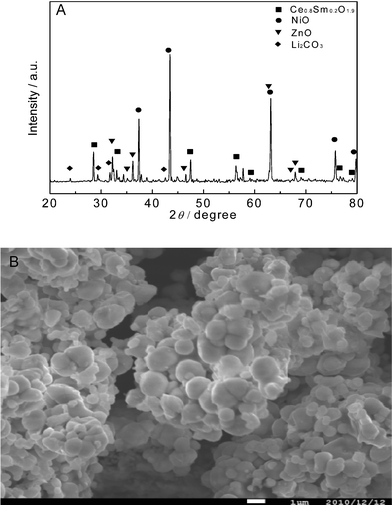 | ||
| Fig. 1 (A) XRD patterns of the as-prepared SDC–LiNiCuZn-oxides composite and NSDC. (B) SEM image of the single-component. | ||
We measured the conductivity (including both electronic (n/p) and ionic conductivity) of the SDC–LiNiCuZn oxide single component. A value of >0.1 S cm−1 at T > 400 °C has been obtained, as shown in Fig. 2. The conductivity is slightly higher in a H2 atmosphere than in air.
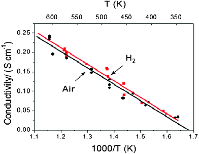 | ||
| Fig. 2 The component material conductivity temperature dependence for the single-component. | ||
NiO normally has a p-type conductivity which can be enhanced by doping, e.g. using Li+ doped NiO.11,12 Usually ZnO displays good n-type conductivity. On the other hand, ZnO may display either electrons or holes in different conditions.13,14 In addition, proton and oxygen ion conduction have been also observed in nickel oxide and zinc oxide.15–21
The single-component device has been demonstrated at both lab and engineering scaled-up devices. Fig. 3A shows a typical device cell voltage and power density versus a current density curve obtained at various temperatures. The OCV is around 1.0 V, i.e. close to the same of a conventional three-component SOFC. A device produced a power density of 594, 697 and 760 mW cm−2 at 520, 540 and 550 °C, respectively. Also, the single component device showed multi-fuel flexibilities being able to be directly operated with hydrocarbon fuels like biogas and alcohol (methanol and ethanol), as shown in Fig. 3B. In initial tests, 350, 480 and 400 mW cm−2 have been achieved respectively for the biogas, methanol and ethanol at 550 °C. We have also demonstrated a larger engineering device with the size of 6 cm × 6 cm (active area 25 cm2). It delivered 10–15 W.
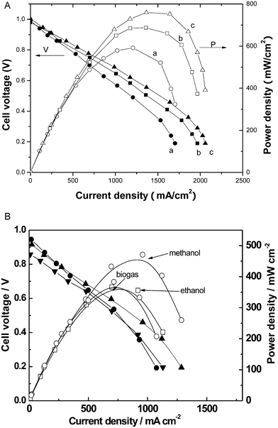 | ||
| Fig. 3 (A) Device performance: voltage and power density versus current density for the single-component device at various temperatures and relevant microstructure. a, b and c are for 520, 540 and 550 °C, respectively. (B) Single-component device performances for hydrocarbon fuels (ethanol, methanol and biogas) at 550 °C. | ||
The device performances were further investigated by varying the fraction of ceria (0, 30, 60, 70 wt%, respectively) to the LiNiCuZn oxides as shown in supplementary Fig. S2.† Even pure LiNiCuZn–oxide (the ceria fraction is 0) did not show a complete short circuit; still an OCV above 0.1 V was observed, and more interestingly a significantly higher current output, more than 200 mA cm−2, was drawn. In fact, despite high electronic conductivity of the pure LiNiCuZn oxide, it has also some ionic (H+ and O2−) conductivity which could be the reason causing no complete short circuit.15–21 More details have been discussed in the ESI.† A conclusion can be made here: the well-balanced electronic and ionic phases and conductivities are very important for the separation of ionic and electronic charges and phases in order to achieve best single-component device performance and to avoid short circuiting problems though the device is constructed by a mixture of electron- and ion-conducting materials. The percolation of ionic and electronic two phases plays a key.
We also studied the component semiconducting properties. Fig. 4 displays the I–V measurement obtained by applying external voltage on the LiNiCuZn -SDC sample in forward bias/mode. After applying a certain bias voltage of ca. 1.1 V, the current increases significantly, indicating semiconducting properties of the material.
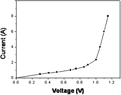 | ||
| Fig. 4 Typical I–V semiconducting curve for the single component. | ||
For the reverse mode, we measured directly device reverse resistance and found that it reached infinite as soon as the device voltage reached above 400 mV under H2–air FC condition. The device showed a one direction current blocking behavior. This is completely different compared to the forward mode (for the FC power delivering) shown in Fig. 4 where a resistance is only at ohm level. These evidences indicate that the single component device exhibits a diode effect for electrons and enables a charge separation in FC operation. This diode effect/junction and the physical principle of p–n junction play a key role for the charge separation to determine a few device functions: (i) no short-circuiting problem; (ii) an internal block to electrons; (iii) non-blocking for ionic passing and transport because a continuous percolating ion phase and conduction paths. These characteristics are obviously different from existing FC science as a pure electrochemical device.
Fig. 5 shows a typical EIS (electrochemical impedance spectra) obtained from the single-component device. The dotted curve shows the experimental results and bold line represents the simulated results. From the equivalent circuit, L (inductance) the effect of the stainless tube is from the testing device. There exist different conductance mechanisms, including electrons, oxygen ions, and protons in the single-component device. In an O2 atmosphere, R1 denotes ohmic resistance mainly caused by oxygen ion and electrons; in this case, the ohmic resistance contains both an electron and ion contribution; R2Q and R3Q denote charge transfer and mass transfer, respectively. In an H2 atmosphere, R1 denotes ohmic resistance for protons, oxygen ions and electrons due to introducing protons from H2;22,23 R2Q and R3Q denote charge transfer and mass transfer, respectively. From the EIS result (Fig. 5), it may be concluded that: (i) proton conductance mixed with electron (in H2) is faster than the oxygen ion conductance mixed with electron (in air) in terms of the ohmic resistance results; (ii) a polarization loss from the cathode condition (air) is also larger than that from the anode (H2); in other words, H2 oxidation is easier to catalyze than O2 reduction. It could be the reduction of Ce4+ in H2 that lead to the difference of EIS makes some complex for analysis; (iii) in addition, the small intercept at the Re Z axis of the semicircle portion in H2 and air indicates that both functional anode and cathode reactions are fast kinetic processes.24,25 This implies that LiNiCuZn-based oxide-SDC materials have a high catalytic activity both for H2 and O2.
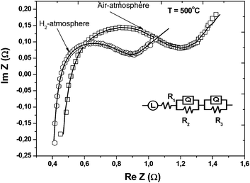 | ||
| Fig. 5 Typical EIS (electrochemical impedance spectra) for the LiNiCuZn oxide-NSDC single-component device in air and H2 at 500 °C, respectively. Experimental data and theoretical simulated results as well as equivalent circuits are included. | ||
Based on the above results joint electrochemical (FC) and physical (solar cell) scientific principles are proposed for the single-component device: (i) an electrochemical FC principle and (ii) a physical p–n junction, same as in a solar cell. In the first case, the device can function as a FC, i.e. in an electrochemical way:
At the H2 contact side:
| H2 → 2H+ +2e− | (1) |
At the air (O2) contact side:
| ½O2 + 2e− → O2− | (2) |
Overall reactions:
| H2 + ½O2 → 2H+ + O2− | (3a) |
| 2H+ + O2− → H2O | (3b) |
| H2 + ½O2 → H2O | (4) |
Thus the single-component device has realized the same function, eqn (4), as a conventional 3-component FC. However, eqn 1–3 (3a and 3b) are different from a conventional FC due to the avoidance of an electrolyte separator in a single-component device. The electron transfer/reaction and electricity generation can be realized directly between the H+ and O2− ions and does not involve ion transportation through a bulk electrolyte separator. While in conventional FCs the ion transport through the electrolyte is critical in order to complete the FC reactions, in the single-component device H+ and O2− ions can diffuse and react on particle surfaces in the mixed electronic (n and p) and ionic conducting materials since both SDC and LiNiZuCu–oxide can conduct O2− and H+ simultaneously. As indicated by Yanjie Xia etc. very recently: “In the single-component fuel cell, ionic transportation process involves movement of O2− ions from the SDC interiors to the surface where the redox reactions occur, a shorter process than that in traditional three-component fuel cells”.26 The use of surface migration of ions in FCs was proposed by van Gool27 before. It is thus possible to use a porous electrolyte to improve the FC performance by making use of the surface migration of proton and oxygen ions.
On the other hand, the physical principle of the device plays a key role in the charge separation and building up a p–n junction. It is unexpected that a device using only a mixed ion and electronic (n and p) component does not cause a short circuit. The charge (electrons and ions) and phase separation (electronic and ionic) phenomena as well as the absence of a short circuiting problem observed in this single-component device deserve further attention. During the H2 and air supply the device voltage and electrical field are built up across the device, as shown in Fig. 6A. The electron and hole separation is driven by the semiconducting material (LiNiCuZn oxide) as shown in Fig. 6B. On the other hand, the ionised particles’ surfaces with H+ and O2− for the ion conductor, SDC of the component may also support and maintain the separation of ionic and electronic phases but in a percolating network with continuous paths for ion conduction. The electrons and holes do not pass through the component, but move to the corresponding counter electrodes (as shown in Fig. 6B) due to the p–n junction. In the H2/fuel and air condition, the single-component device can function as a diode to block the electrons internally. This was observed and discussed above. We find similarities here to the charge separation and construction in a solar cell.28
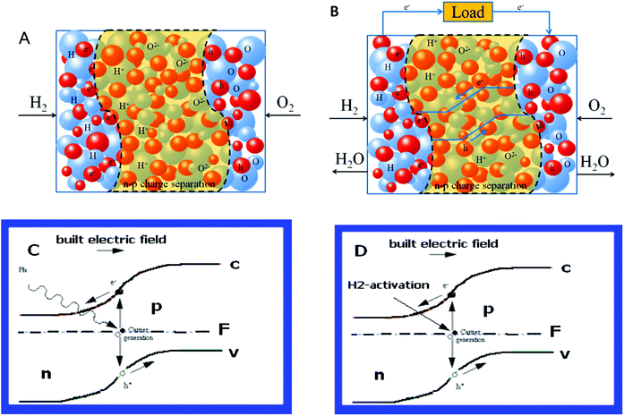 | ||
| Fig. 6 (A) Initiated by the H2 and air (O2) reactions due to bi-catalysis of the component the device sets up the cell voltage and built-in electric field which drives the charge separations for electrons and holes as well as the ionic and electronic phases. (B) The electrons and holes form a junction barrier to support the device function, the open circuit voltage as high as for the fuel cell due to H2–air processes going with the component, the electrons and holes moving towards each counter electrode without passing internally through the component. The ions (H+ and O2−) and electrons/holes contribute to the current output and conduct effectively. (C) & (D) Similarities of scientific principle between the solar cell and the new device, where n: n-type, p: p-type, F: Fermi level, c: conduction band, v: valence band. | ||
Fig. 6C and 6D further present a similarity of scientific principles between the photovoltaic device and this reported device. A solar cell consists basically of a junction formed between n-type and p-type semiconductors, either of the same material (homojunction) or different materials (heterojunction),29,30 in which the Fermi level on either side of the junction cause the valence and conduction bands to bend, i.e. band-bending. These bent bands represent a built-in electric field over the depletion region. If a photon with energy greater than the band gap of the semiconductor passes through the solar cell it may be absorbed by the material. It takes the form of a band-to-band electronic transition, which produces an electron/hole pair. The electron and hole may be separated by the electric field, causing one quantum of charge to flow through an external load.
A difference for the new device is also to use H2/fuel (e.g. alcohol) to activate the device. Fig. 6D presents the same principle but the charge carrier (e−) is activated by H2. When a proton (H+) is formed an electron is produced in the same time. Negative and positive charges are generated on surfaces of the n-type and p-type semiconductors, respectively. The junction between them becomes depleted of charge carriers, i.e. non-conduction, like a p–n junction. Consequently, a cell potential is generated and electric energy can be taken out of the device. The situation is similar to already known resources of photovoltages that can arise from the gradients of both the photoelectric field and the equilibrium densities and mobilities of electrons and holes.31
To support this H2 activation mechanism, we further constructed a device which was blocked on one side using aluminium foil, leaving only one side supplied by H2. In this case we avoid the H2–air FC reaction. Before H2 was supplied, no device voltage was observed. Once H2 was supplied, a device voltage appeared which rapidly reached a significantly high voltage between 600–800 mV in temperatures between 450–580 °C. Sole H2 or protons produced due to component catalyst to H2 activation could produce electrons which made a n–p concentration gradient that drove a device voltage. The situation is similar to already known sources of the photovoltage that can arise from the gradients of both the photoelectric field and the equilibrium densities and mobilities of electrons and holes.31
The same experiment was also completed for the conventional anode/electrolyte/cathode three-component device using also one Al-blocking electrode; no cell voltage was observed with H2 activation. This is reasonable since no p–n junction is formed due to the separation from a pure electrolyte.
Furthermore, we have measured the device by switching H2 and air supplies from both sides, the device showed a completely symmetric response, see Fig. S3.† In this case, Ag paste used on the single component may be suggested to function as the current collector. Thus it is reasonable that the device showed data as symmetric when switching the two electrodes to be either anode or cathode.
Finally, we conducted a durability test for the device discharged under a constant load, see Fig. S4,† water was observed from both sides during operation which proves a continuous conversion of chemical energy of H2 to electricity following the FC reaction mechanism proposed above. We thus present an animation of the single component device working principle in the supplementary video† for a viable model joining FC and p–n junction principles.
Conclusions
To summarize we have made further developments on the single-component device, both scientifically and technologically, with combined electrochemical and physical principles, where the device physics plays a key role to make the device functioning in parallel to FC reactions. Based on a seemingly new scientific principle the single-component possesses both ionic conductivity and semi-conductivity (n and p) as well as efficient catalytic functions for H2 and O2 which integrate the FC functions for the anode, the electrolyte and the cathode into one component with a homogenous mixture and percolating paths/network for both the ionic and electronic phases. Apparently this could be a new energy conversion technology joining FC and solar cell principles to realize the same function as a FC. The new materials and functionalities can make both the design and manufacturing of the device less complicated, which of course is important for a cost reduction of the production and the energy conversion. It is our hope that the results we report may positively effect the development of both advanced fuel cells and solar cells.Acknowledgements
Funding from VINNOVA (Swedish Agency for Innovation Systems) and KIC Innoenergy is highly acknowledged.References
- A. Salvatore, P. Bruce, B. Scrosati, J. M. Tarascon and W. Schalkwijk, Nat. Mater., 2005, 4, 366–377 CrossRef.
- B. Zhu, X. Wang, Y. Ma, R. Raza, H. Qin and L. Fan, Electrochem. Commun., 2011, 13, 225–227 CrossRef CAS.
- W. R. Grove, Phil. Mag. Ser., 1839, 314, 127–130 Search PubMed.
- B. C. H. Steele, J. Mater. Sci., 2001, 36, 1053–1068 CrossRef CAS.
- B. C. H. Steel and A. Heinzel, Nature, 2001, 414, 345–352 CrossRef.
- R. W. James, Nat. Mater., 2006, 5, 541–544 CrossRef.
- B. Zhu, R. Raza, G. Abbas and M. Singh, Adv. Funct. Mater., 2011, 21, 2465 CrossRef CAS.
- B. Zhu, R. Raza, H. Qin, Q. Liu and L. Fan, Energy Environ. Sci., 2011, 4, 2986–2992 CAS.
- H. Gallagher, Materials Views, 2011-05-11 http://www.materialsviews.com/details/news/1058061/The_Economics_of_the_Hydrogen_Economy.html Search PubMed.
- R. Raza, X. Wang, Y. Ma and B. Zhu, Int. J. Hydrogen Energy, 2010, 35, 2684–3688 CrossRef CAS.
- D. Michael, D. B. Buchholz, W. H. Alexander and P. H. C. Robert, Proc. Natl. Acad. Sci. U. S. A., 2008, 8, 2783–2787 Search PubMed.
- H. P. Rooksgyi and M. W. Vernon, J. Appl. Phys., 1966, 17, 1227–1228 Search PubMed.
- S. K. Mandal, A.K. Das and T. K. Nath, Appl. Phys. Lett., 2006, 89, 144105 CrossRef.
- Ü. Özgür, Y. Alivov, C. Liu, A. Teke, M. A. Reshchikov, S. Doğan, V. Avrutin, S-J. Cho and H. Morkoç, J. Appl. Phys., 2005, 98, 041301–041403 CrossRef.
- T. Norby, Solid State Ionics, 1990, 40–41, 857–862 CrossRef CAS.
- L. Chen, L. Li and G. Li, Solid State Ionics, 2008, 179, 712–717 CrossRef CAS.
- S. Tao, Q. Wu, Z. Zhan and G. Meng, Solid State Ionics, 1999, 124, 53–59 CrossRef CAS.
- J. C. Giron, (Paris, FR), United States, Saint-gobain, Vitrage (Courbevoie, FR) 2001, 6277523.
- J. Carrasco and N. Lopez, Phys. Rev. Lett., 2004, 93, 225502 CrossRef CAS.
- H. Saltsburg and D. P. Snowden, Surf. Sci., 1964, 2, 288–297 CrossRef CAS.
- C. Dubois, C. Monty and J. Philibert, Solid State Ionics, 1984, 12, 75–78 CrossRef CAS.
- A. S. V. Ferreira, C. M. C. Soares, F. M. H. L. R Figueiredo and F. M. B. Marques, Int. J. Hydrogen Energy, 2011, 36, 3704–3711 CrossRef CAS.
- X. Wang, Y. Ma, S. Li, B. Zhu and M. Muhammed, J. Power Sources, 2011, 196, 2754–2758 CrossRef CAS.
- A. J. Bard L. R. Faulkner, Electrochemical Methods: Fundamentals and Applications, 2nd edn, 2001, pp. 380–387 (John Wiley & Sons, Inc., New York) Search PubMed.
- G. Grueneberg, W. Vielstich and D. J. G. Ives, Wiley-Interscience: New York, USA, 1965, pp. 374–376.
- Y. Xia, X. Liu, Y. Bai, H. Li, X. Deng, X. Niu, X. Wu, D. Zhou, M. Lv, Z. Wang and J. Meng, RSC Adv., 2012, 2, 3828 RSC.
- W. Gool Van, Philips Res. Repts, 1965, 20, 81–93 Search PubMed.
- B. O. Regan and M. Grätzel, Nature, 1991, 353, 737–740 CrossRef.
- J. Katayama, K. Ito, M. Matsuoka and J. Tamaki, J. Appl. Electrochem., 2004, 34, 687–692 CrossRef CAS.
- S. Maslenikov and M. Fedorov, Russ. Phys. J., 1997, 40, 60–63 CrossRef CAS.
- R. Kishore, Solid-State Electron., 1990, 33, 1049–1054 CrossRef.
Footnote |
| † Electronic supplementary information (ESI) available. See DOI: 10.1039/c2ra01234k |
| This journal is © The Royal Society of Chemistry 2012 |