Non-photobleaching YAG:Ce nanoparticles for optical imaging with blue excitation†
Biao
Dong
a,
Jing
Wang
a,
Jiao
Sun
b,
Sai
Xu
a,
Xue
Bai
a,
Zhenlong
Jiang
a,
Lei
Xia
a,
Liankun
Sun
b and
Hongwei
Song
*a
aState Key Laboratory on Integrated Optoelectronics, College of Electronic Science and Engineering, Jilin University, Changchun 130012, P. R. China. E-mail: hwsong2005@yahoo.com.cn; Fax: 86-431-85155129
bNorman Bethune College of Medicine, Jilin University, Changchun, Jilin Province 130021, China
First published on 14th February 2012
Abstract
Hydrophilic Y3Al5O12 (YAG) and (YxGd1−x)3Al5O12 nanoparticles (NPs) doped with Ce3+ ions were synthesized by a solvothermal method and used for cell-imaging. The crystallite sizes and photoluminescence spectra were tuned by lanthanide ions (Gd3+, Ce3+) doping. Without any surface modification, the YAG:Ce NPs show good water solubility, colloid stability and low toxicity. The intracellular uptake of the YAG:Ce NPs was visualized using a confocal fluorescence microscope under the excitation of a 457 nm laser due to the strong absorption of fluorescent NPs in the blue region. The non-bleaching property was confirmed by comparing with organic dye Alexa488. Overall, we demonstrated that the YAG:Ce NPs can serve as an efficient fluorescence imaging agent with visible light excitation and without photo-bleaching, which shows great foreground in bio-imaging, especially with confocal imaging system for in vitro studies.
1. Introduction
The rapid development of drug delivery, cancer cell diagnostics, and therapeutics is now stimulating researchers to find more efficient biological labels which are more resistant to photo-bleaching, and are nontoxic, biocompatible and monochromatic relative to traditional organic dyes. Various semiconductor quantum dots (QDs, such as CdS, CdSe, CdTe) have been applied in biological analysis due to their unique properties, such as high quantum yields of photoluminescence (PL), broad excitation spectra, and narrow emission bandwidths.1–4 However, these QDs are composed of cadmium salts which can release soluble cadmium after cellular labeling, leading to toxicity, though some reports suggest surface modification of the QDs can address this issue.5 Finding more appropriate luminescent labels that can meet safety requirements is crucial for medical applications.Rare-earth doped nanophosphors should be such an alternative which show a high chemical stability, high quantum yield, low toxicity, and tunable optical properties by varying lanthanide dopants and the host matrix.6–8 Rare-earth luminescent centers can be excited by UV and infrared light to give emission in the visible region.9–10 Up to now, IR-excited rare-earth up-converting nanophosphors (UCNPs) have been proposed to be important biological luminescent labels and have been applied successfully in some research works for bio-imaging in living cells12–16 due to their advantages, such as their non-invasive nature and the relatively deep penetration of NIR radiation, and probable absence of autofluorescence of biological tissues. Besides UCNPs, rare-earth down-converting nanophosphors (DCNPs) can also find applications in the bio-imaging field. However, generally, DCNPs show limitations in bio-imaging, because excitation is generally in the UV region, which may cause damage to the cells and autofluorescence of biological tissues. In this work, nevertheless, yttrium aluminum garnet (Y3Al5O12, YAG) doped with Ce3+ is demonstrated as an new bio-imaging label with good luminescence properties (blue excitation and yellow emission) and biocompatibility, and is a viable alternative to QDs and organic dyes.
YAG:Ce, as a well-known luminescent material, has a rich history and a wide variety of applications.17–19 It has been found to be suitable for converting blue-light emitting diode (LED) radiation into a very broad band yellow emission, which can be used as one of the most common methods for producing white light with a gallium nitride-based blue LED.20–22 Inspired by this notion, it is possible that nanosized YAG:Ce nanoparticles (NPs) can serve as a bio-imaging label when introduced into cells and excited with blue light. In addition, the common microscopy applied in imaging, such as fluorescence microscopy and laser scanning confocal microscopy, are designed to suit the photoconversion mechanism of organic dyes and QDs, which is a Stokes process. Therefore, YAG:Ce NPs, with blue excitation and yellow emission, can offer new opportunities for biological tagging applications.
It is known that YAG:Ce possesses notable chemical and physical properties due to its garnet structure which usually requires prolonged heating at high temperature (around 1600 °C) to overcome the competitive formation of secondary phases.23 In this study, a solvothermal method was chosen to synthesize YAG NPs because it could bring many advantages in control of the particle morphology, size and optical properties. In a closed liquid environment of high temperature and high pressure, it can avoid increase of particle size and aggregation and, in particular for YAG:Ce, the oxidation of Ce3+ to Ce4+.24–27 Furthermore, in bio-imaging water-solubility is an important and required characteristic, and the solvothermal method is a good choice to synthesize hydrophilic NPs without removing organic hydrophilic groups attached on the surface, such as OH− and COO−, in the crystallization process.
Various solvents have been employed in the solvothermal method for the preparation of YAG, such as ammonium hydrogen carbonate,28 oleylamine,29 1,4-butanediol27 and solvent mixtures. In this work, we employed modifications to Nyman's method.27 NPs used for bio-applications should always be subject to surface modification with hydrophilic molecules or polymer to enhance their water solubility. Fortunately, hydroxy groups inherent in the synthesis of our solvothermal YAG NPs lead to good water-solubility and colloidal stability, and the YAG NPs show good cytotoxicity and cell imaging properties.
As a green–yellow biomarker, the luminescence stability and resistance to photo-bleaching of YAG:Ce NPs were also investigated compared with the well-known organic dye Alexa488. The results indicate that YAG:Ce has high luminescence stability and may find broad application in bio-imaging.
2. Experimental section
Synthesis of hydrophilic YAG NPs
Similar to Nyman's protocol,27 YAG:Ce nanocrystals were solvothermally synthesized with some modifications. In a typical synthesis of Y3(1−x)Al5O12:Cex (x = 0.005, 0.01, 0.03, 0.06 and 0.1) and Y3(0.99-x)Gd3xAl5O12:Ce0.01 (x = 0.1, 0.3, 0.6 and 0.99) NPs, corresponding lanthanide acetate hydrates were used. Stoichiometric amounts of yttrium acetate hydrate (Y(CH3COO)3), aluminum isopropoxide (Al(OPri)3), cerium acetate hydrate (Ce(CH3COO)3) and gadolinium acetate hydrate (Gd(CH3COO)3) were mixed and dissolved in 22 ml of a mixed solvent (80 vol% 1,4-butanediol (1,4-BD)–10 vol% diethylene glycol (DEG)–10 vol% ethanol) in a beaker with magnetic stirring for 3 h. Then the mixture was transferred into a 50 ml Teflon-lined autoclave and heated to 240 °C and kept at that temperature for 1–2 days. After cooling to room temperature, a yellowish colloidal solution was obtained. After washing with ethanol and centrifugation (9500 rpm, 10 min), the purified YAG:Ce NPs were readily dispersed into water.Measurements and characterization of YAG:Ce
Transmission electron microscopy (TEM) images and energy-dispersive X-ray (EDX) spectra were taken on a Hitachi H-800 (Hitachi Company) electron microscope equipped with an energy-dispersive X-ray spectrometer. The crystalline structure of samples were characterized by X-ray diffraction (XRD) (Rigaku D/max-rA power diffractometer using Cu-Kα (λ = 1.54178 Å) radiation). The Fourier-transform infrared (FTIR) absorption spectra were measured using a Shimadzu DT-40 model 883 IR Spectrophotometer. Z-Potential measurements were performed using a Zeta sizer NanoZS (Malvern Instruments, USA). Fluorescence spectra were recorded with a Hitachi F-4500 fluorescent spectrometer. For the measurement of the fluorescence dynamics, a FLS-920 single photon spectrometer equipped with a nanosecond flash H2-lamp was employed as excitation and detection source.Bio-experiments
3. Results and discussion
Synthesis and characterization
YAG:Ce and YAG:Gd,Ce NPs were synthesized using a procedure reported by Nyman et al. with some modifications. Generally, the crystallinity of the product can be greatly improved by increasing reaction temperature or pressure in hydrothermal treatment. In this case, for this aim, small amounts of ethanol were added besides 14-BD and DEG solvents to increase the pressure of the autoclave due to its low boiling point. Also, as a small hydroxy molecule it may help to increase the water solubility of YAG NPs. In this solvent system, reaction temperature and time were important and temperature >230 °C and time >24 h were necessary for crystallization (XRD patterns of the samples with different reaction times are shown in Fig. S1, ESI†). The samples prepared at 240 °C and 48 h were chosen for bio-application due to their good crystallization and high luminescent intensity. DEG serving as a co-solvent played an important role in reducing impurities during the synthesis as observed by Nyman,27 In this work, besides DEG, some other hydroxy solvents, such as 1-butanol and 1-hexanol, were also proved to work well for the preparation of YAG NPs (Fig. S1, ESI†). In addition, lanthanide acetate and Al isopropoxide were shown to be essential. When lanthanide trifluoroacetic acid salts, nitrates and aluminum nitrate were employed, only amorphous powders could be obtained, which indicated that organometallic salts in such a reaction system were necessary due to their slow decomposition and, consequently, slow crystallization. Furthermore, an alternative aluminum organometallic salt, aluminum acetylacetonate could be used as the aluminum source and YAG nanocrystals were successfully formed, which confirmed the above results (Fig. S1, ESI†).It is worth stressing that the NPs obtained from these solvents formed a clear, aggregate-free solution in water without any surface modification, because the hydroxy solvents may attach on the surface of the NPs in the formation process and greatly enhanced the water solubility. A TEM image (Fig. 1a) shows well-dispersed spherical YAG:Ce1% NPs prepared from DEG–14-BD–ethanol with a mean diameter of about 15 nm and a relatively narrow size distribution, as plotted in Fig. 1b.
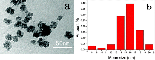 | ||
| Fig. 1 TEM image of YAG:Ce1% NPs (a) and size distribution (b). | ||
From EDX analysis, we determined that final Ce contents in YAG:Ce1% and YAG:Ce6% NPs are 0.65% and 4.48%. This indicated that Ce content in YAG NPs was a little lower than that in the mixture before solvothermal reaction (Fig. S2, ESI†). Oxidation of Ce3+ to Ce4+ was not observed in the solvothermal process, as the 1,4-BD remained colorless, even after extensive heating, even upon diethylene glycol and ethanol addition. Otherwise, the solvent would became dark due to redox reactions.27 The stability of 1,4-BD prevented the change of oxidation state of cerium in this redox-sensitive synthesis. These NPs also showed high chemical stability because they could not be dissolved in aqua regia for weeks.
The XRD patterns of the samples were also studied (Fig. 2a), which revealed that YAG NPs with different Ce3+ doping levels (0.5–10%) had been formed through hydrothermal treatment. All of the diffraction peaks for YAG are characteristic of a pure cubic phase (JCPDS card No. 079-1892). The Ce3+ loading induces sharpening of the XRD peaks, indicating that the grain size increases with increasing Ce3+ content. The variation in the average grain size, calculated from the broadening of the strongest (420) peak using the Scherrer equation, as a function of Ce3+ content is depicted in Fig. 2b. The addition of Ce3+ increases the average YAG crystalline size from about 14 nm with 0.5 mol% doping up to about 21 nm in the 10 mol% sample. The XRD results are in agreement with the observations in TEM studies. Based on the Ce3+ 1 mol% doping, different amounts of Gd3+ ions were doped into the YAG to substitute Y ions (10, 30, 60 and 99 mol%). In Fig. 2c, with different Gd3+ ions loading, the diffraction peaks of the products are all consistent with a garnet structure. An increase of average grain size was also observed with increased Gd3+ loading from the calculations using the Scherrer equation. As the Gd3+ adoption increases from 10 to 30%, the grain size increases slightly from that of YAG:Ce1% NPs. When the doping reaches 60% and when Y3+ ions are all substituted by Gd3+ ions, the grain size increases obviously to ∼22 and ∼36 nm, respectively, Fig. 2d. It is known that Y3Al5O12 (space group Ia3d = Oh10) features Al3+ ions coordinated to nearest-neighboring oxygens with octahedral and tetrahedral point symmetry (a and d sites) and Y3+ ions occupy the dodecahedral c site due to their smaller ionic radius (the ionic radius of Y3+, Gd3+ and Ce3+ are 0.90, 0.94 and 1.03 Å,30 respectively). So the Ce3+ and Gd3+ ions act as substitutional dopants for Y ions in the c sites with D2 local symmetry, with dodecahedral oxygen coordination. The larger radius of Gd3+ and Ce3+ ions can cause a variation in the local lattice structure and, consequently, an expansion distortion effect which may be the reason for the increase of the crystallite sizes. The influence of lanthanide ion substitution on crystallite size comes from two factors: ionic radius and adsorption amount. In this work, because of the bigger ionic radius of Ce3+ ions (1.02 Å), obvious increase of crystallite size can be observed even in low doping levels (≤10 mol%). As to Gd3+, which is a little bigger than Y3+ in ionic radius, the crystallite size does not vary obviously below 30 mol% doping. However, as the doping amount reaches 60% and more, an obvious crystallite size increase occurs due to the large-scale substitution. In addition, the diffraction peak of 420 shifts to smaller angle direction as the amount of Gd3+ ion increases (inset of Fig. 2c), which also indicates that the cell parameters increase, and, consequently, the crystallite size increases.47
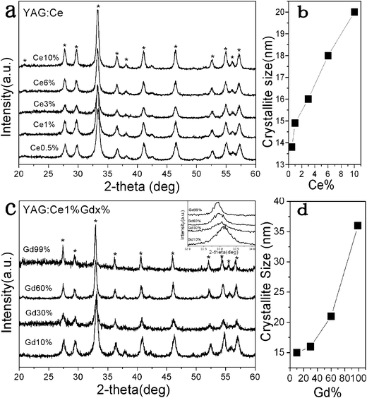 | ||
| Fig. 2 XRD patterns of Y3(1−x)Al5O12:Cex (a) and Y3(0.99−x)Gd3xAl5O12:Ce0.01 NPs (c) and the corresponding average grain sizes calculated from the 420 peak using the Scherrer equation (b) and (d). | ||
IR analysis
Infrared analysis of the YAG NPs with different Ce concentrations and the bulk YAG sample in Fig. 3 shows many hydroxy molecules are attached on the surface of the YAG NPs. The strong band at 3500 cm−1 can be attributed to OH groups of the hydroxyl solvents, which are responsible for the good water solubility. It can be confirmed that the primary molecules on the surface are 1,4-BD, because the bands can correlate with a spectrum of neat 1,4-BD which is not present in the bulk sample.31 In addition, there is no variation in the IR spectra of the YAG NPs prepared with substitution of DEG by butanol and hexanol, which indicates that the 1,4-BD plays an important role in the crystal formation and water-solubility (see Fig. S3, ESI†). The peaks at 1425 and 1570 cm−1 are assigned to carboxyl groups derived from the starting lanthanide acetate.32 These are characteristic of carboxyl groups coordinated to metal ions on the surface of the NPs.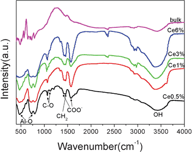 | ||
| Fig. 3 Infrared spectra of YAG:Ce (0.5–6%) NPs from 1,4-butanediol–DEG–ethanol and bulk YAG:Ce powder for comparison. The peaks marked BD correspond to 1,4-butanediol. | ||
Luminescent properties
Fig. 4 shows the photoluminescence (PL) and photoluminescence excitation (PLE) spectra for nano-YAG:Ce NPs synthesized in 1,4-BD–10%-DEG–ethanol. The samples with different Ce3+ doping amount all exhibit a characteristic broad, yellow–green emission originating from the lowest-lying 5d state to the 4f ground state, having a maximum around 530 nm.27,33,34 The PLE spectrum of the yellow band consists of a group of PLE bands, including a blue PLE band at 450 nm corresponding to the transition from the ground state to the lowest-lying 5d state, and an ultraviolet (UV) PLE band corresponding to the upper 5d state, located at 340 nm. The schematic energy level diagram for Ce3+ in YAG in Fig. 5 explains these phenomena well. In the doping scale of 0.5–6 mol% of Ce3+ ions, the sample with 1 mol% doping showed the highest emission intensity, and was chosen for the following bio-experiments.35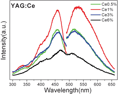 | ||
| Fig. 4 Excitation spectrum and emission spectra of YAG:Ce (0.5–6%) NPs under 450 nm excitation. | ||
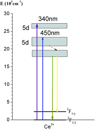 | ||
| Fig. 5 Schematic diagram of energy levels of Ce3+ in YAG. | ||
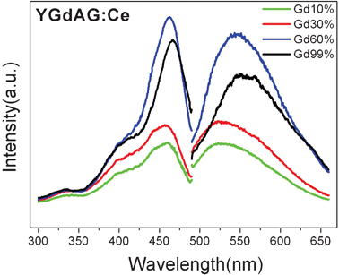
The corresponding spectra of samples with different Gd3+ ion loading into the YAG:Ce1% are also shown in Fig. 6. The PL spectra of YAG:Gd,Ce also consist of one broad band, which is due to two strongly overlapped bands typical of optical transitions from the lowest excited (5d) sublevel to spin–orbit split 4f sublevels 2F5/2 and 2F7/2 in the Ce3+ ions. The PL intensity increases as the Gd3+ ions loading increases and the highest emission intensity is obtained as the Gd3+ concentration reaches 60 mol% for substitution of Y3+ ions. For these samples, the striking feature of the YAG:Gd,Ce emission is a remarkable red shift as the Gd3+ ions loading increases. The normalized spectra are presented in Fig. 7. In respect to maximum position of the sample with a Gd3+ concentration of 10 mol%, the sample with all substitution by Gd3+ (99 mol%) exhibits a redshift for about 30 nm. It is known that the 5d excited state is localized and strongly influenced by the surrounding crystal field. The red shift of the emission implies that the crystal field strength around Ce3+ ion was somewhat increased in a nanosized regime.34,36,37
 | ||
| Fig. 6 Excitation spectrum and emission spectra of Y3(0.99−x)Gd3xAl5O12:Ce0.01 NPs under 450 nm excitation. | ||
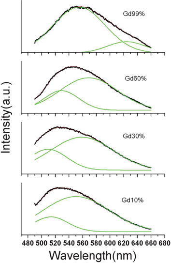 | ||
| Fig. 7 Normalized emission spectra of Y3(0.99−x)Gd3xAl5O12:Ce0.01 NPs fitting with a double-peak Gaussian function. | ||
Due to the spin–orbit interaction, the 4f electronic configuration of Ce3+ has two ground states, 2F5/2 and 2F7/2, and, therefore, the emission always consists of an asymmetric band. So the emission spectra can be dissolved by double Gaussian functions. In Fig. 7, all the emission spectra can be fit well to a double-peak Gaussian function. Because the whole emission spectra red shift as the Gd3+ loading increases, the two peaks both undergo a red shift. However, the proportion of the first peak increases as the Gd3+ loading increases, which indicates that the transitions of the emitting state to the 2F5/2 energy level becomes more effective compared to the upper 2F7/2 energy level. The increase of crystallite size and the enhancement of crystallization may help to activate the transitions to the lower energy level.
The decay dynamics of (Y0.99Ce0.01)3Al5O12 and (Gd0.99Ce0.01)3Al5O12 NPs were monitored at 545 nm (λex = 450 nm). The result showed that they both consisted of a shorter decay time constant τ1 and a longer decay constant τ2. For the two samples, τ1 values were determined to be 14.5 and 15.3 ns, respectively, while τ2 was 65.3 and 66.8 ns, respectively. Therefore, though the position and intensity of Ce3+ emission could be modified by Gd3+ doping, the lifetimes of Ce3+ did not change, suggesting that no energy transfer occurred between Ce3+ and Gd3+.
Luminescent stability and cytotoxicity of colloids
Biological safety is considered to be one of the most important factors to evaluate biomaterials, though toxicity is the least understood feature of NPs when it comes to their application for imaging.38,39 Toxicity of NPs can be due to several factors such as concentration, hydrodynamic size, surface charge and the route of administration. Based on the results published recently cellular uptake of NPs depends on their sedimentation and diffusion velocities in culture medium, which should be considered when performing in vitro studies, especially for large and/or heavy NPs. Therefore, the water solubility is a very important factor in the toxicity of NPs, and emphasis should be given on selecting the right size and biocompatible coatings of NPs. To reduce the toxicity of NPs, such as carbon, gold, silver, manganese, lanthanide based nanomaterials, PEG, chitosan and poly(vinyl alcohol)40,41 have also been employed in the biocompatible coating process to address some of the above issues. However, the linkage of the surfactant and NPs may not be tight because this coating step is always performed in a relatively gentle environment. In this work, however, no surfactant was used because the YAG NPs have inherent water solubility due to the hydroxy groups attached on the surface. In addition, we determined that the zeta potential of YAG:Ce1%, YAG:Ce3% and YAG:Ce6% samples were 27.2, 30.5 and 33.2 mV in water, respectively, and 1.43, 2.28 and 2.46 mV in ethanol. Therefore, the charge repulsion may also help to enhance the dispersibility in water. Consequently, these NPs show good colloid stability in water and biological medium, and thus low toxicity. Fig. 8 shows the emission spectra of the YAG:Ce(1%) colloid with size of 15 nm dispersed in water with a concentration of 2.5 mg ml−1. The emission signal was recorded every hour with excitation of 450 nm from a xenon lamp and a power density of 28 mW cm−2; even over 32 h no change was observed. Luminescence photographs of the YAG:Ce colloids are shown in the upper inset of Fig. 8 and bright green–yellow light could be observed with a filter of 490 nm. The corresponding intensity of the emission monitoring at 536 nm was recorded as a function of time and plotted in the lower inset of Fig. 8. The results also confirmed that the YAG:Ce colloids showed high stability in this measuring period. The luminescence stability of YAG:Ce in DMEM medium was also measured (data not shown), and we obtained the same result as for the stability in water. Note that the concentration of 2.5 mg ml−1 is relatively high for bio-application. We also found that the lower the concentration of the YAG NPs was, the better the stability of the colloids was. A YAG colloidal solution of several hundred μg ml−1 retained stable for several weeks without any precipitate.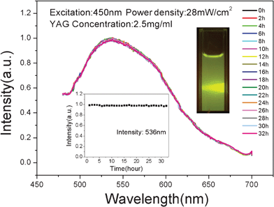 | ||
| Fig. 8 The emission spectra of YAG:Ce(1%) colloid dispersed in water at a concentration of 2.5 mg ml−1. The excitation is at 450 nm and power density is 28 mW cm−2 (Xe lamp, 32 hours without any change in measuring process). Top inset: luminescence photographs of YAG:Ce colloids with a filter of 490 nm. Bottom inset: corresponding intensity of emissions monitoring at 536 nm in this measuring period. | ||
The YAG:Ce NPs were evaluated for their potential application as cellular imaging probes by first examining their cytotoxic effects in a MTT cell proliferation assay (MTT = (3-(4,5-dimethylthiazol-2-yl)-2,5-diphenyltetrazolium bromide, a tetrazole). The viability of cells upon exposure to the YAG:Ce(1%) NPs were assessed by detecting mitochondrial function as shown in Fig. 9. The cytotoxic effect of the NPs on the mitochondrial activity of the cells increased in relation to increasing nanocrystal concentration. For cells exposed to YAG:Ce NPs for 24 h incubation, the NPs began to show a degree of cytotoxicity above 25 μg ml−1. At 300 μg ml−1 more than 90% of the HepG2 cells survived, and at 750 μg ml−1, the cell viabilities were over 70%, which showed the low toxicity of YAG:Ce NPs. Therefore, these NPs without any surface modification can be readily used for further bio-experiments using a concentration of 300 μg ml−1.
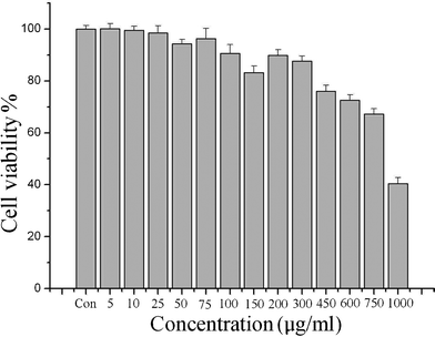 | ||
| Fig. 9 Viability of cells exposed to different concentration of YAG:Ce NPs | ||
Non-photobleaching property of YAG:Ce NPs
As green–yellow biomarkers, besides low toxicity, these YAG:Ce NPs also showed promising nonbleaching property. Fig. 10b presents the luminescent intensity of a cell incubated with the YAG:Ce NPs monitored by a confocal microscope with exciting lasers of 405, 457 and 488 nm. For comparison, the well known green organic dye Alexa488 was employed with the same experimental parameters, plotted in Fig. 10a. The scanning time with these lasers was 600 s and the acquisition time interval was 3 s. The luminescent intensity of the monitoring area of the Alexa488 stained cell showed a rapid decline of 84% in 10 min, while the luminescence bleaching of YAG:Ce was only 24%. The photographs in Fig. 10a and b show the variation of the luminescent intensity of a part of a cell labeled with Alexa488 and YAG:Ce, respectively. A substantial intensity decrease can be seen in the image of the Alexa488 stained cell after laser scanning, while it is nearly unchanged with the YAG:Ce labeled cell after the blue laser irradiation with the same power density. It should be mentioned that after 1 min, Alexa488 showed a 64% decline in luminescent intensity, while it was only 7% for YAG:Ce NPs. Also, if these YAG:Ce NPs are employed for imaging with a fluorescence microscope with excitation of blue light from a mercury lamp, they genuinely are non-bleaching biomarkers. We have detected the luminescent stability of these YAG:Ce NPs under irradiation of monochromatic light of 450 nm for 80 min and no intensity variation can be observed in this period (Fig. S4, ESI†).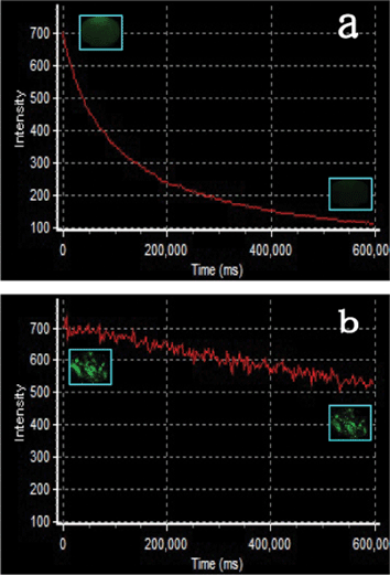 | ||
| Fig. 10 Nonbleaching property test of YAG:Ce biolabels in contrast with Alexa488. The luminescent intensity of a cell incubated with the YAG:Ce NPs and Alexa488 was monitored by a confocal microscope with exciting lasers of 405, 457 and 488 nm. Scanning time: 600 s; acquisition time interval: 3 s. Insets are the first and last images of the cells incubated with Alexa488 and YAG:Ce NPs in the monitoring process. The images are false colored. | ||
Cell imaging
One of the major applications of fluorescent probes in the biological field is labeling cells. Therefore, the biomarkers should be attached on the membrane of the cell or uptaken into the cell to provide internal information. However, many inorganic biomarkers can only achieve the function of finding the position but not imaging the structure of cells because endocytosis could be blocked by poor solubility or large organic molecules used to make NPs hydrophilic.42,43 In this work, the good biocompatibility and low toxicity can help YAG:Ce NPs to image the cell easily. As displayed in Fig. 11a and b, HepG2 cells treated with YAG:Ce NPs for 3 and 6 h show luminescent signals at 500–600 nm (green channel) under 457 nm excitation with a confocal microscope. The overlays of the luminescent image (green channel) and bright field image indicate that emission signal distributions from YAG:Ce are strongly correlated with the profile of HepG2 cells. It also can be seen that the cells with an incubation time of 6 h display strong luminescence in the green channel relative to that of 3 h, suggesting a better internalization of YAG:Ce NPs for the cells as the incubation time increases. Note that the incubation time of 3 h is enough for the cell imaging with YAG:Ce NPs and, furthermore, the oval nucleus can be distinguished by the relative intensity contrast because the YAG NPs can not pass through the nuclear pore complex without nuclear localization signal.44–46 However, if too many YAG NPs were uptaken into the cytoplasm, the nucleus can not be recognized due to the faint luminescent intensity contrast. Moreover, it should be pointed out that no background autofluorescence signal can be found in the luminescent images with such a long wavelength laser excitation, demonstrating that the YAG:Ce is an suitable candidate in bioimaging, especially for confocal imaging systems. Other lasers of 405 and 488 nm which are always equipped in confocal microscope can also be used for excitation of YAG:Ce NPs due to the wide absorption. The imaging function of these NPs were also confirmed with another cancerous cell BC-37 (Fig. S5, ESI†), which indicates the non-specific imaging property of the YAG:Ce NPs. In our work, the one-step synthesised NPs can be easily linked to antibody or target peptides that can bind to specific receptors on or in the cells, due to the groups on the surface, which then can be used to aid early diagnosis of cancer.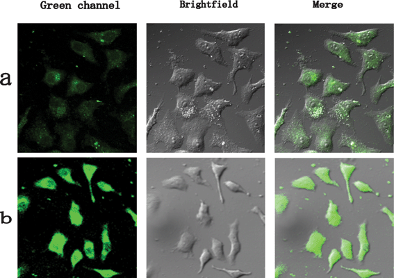 | ||
| Fig. 11 Confocal, bright field, and superimposed images of live HepG2 cells labeled with YAG:Ce NPs with different incubation times. The images are false colored. | ||
4. Conclusion
In summary, we have demonstrated a new green–yellow emissive YAG:Ce NPs for bioimaging with excitation of blue light, to our knowledge, for the first time. Solvothermal synthesis was employed for the formation of YAG:Ce NPs modified with hydroxy groups which render a high dispersibility in water and colloid stability. The crystallite sizes can be controlled by lanthanide ion doping, and, in addition, the emission can also be tuned due to the influence on the crystal field caused by Gd(III) ions. Owing to the small size and low toxicity, the YAG:Ce NPs can be easily uptaken into the cytoplasm of the cells and give luminescent signals recorded by a confocal microscope with high definition which can distinguish the nucleus of cells. It should be mentioned that the NPs can be considered as a candidate material for confocal imaging systems because the common lasers of 405, 457 and 488 nm that are equipped on the confocal microscope can all excite the YAG:Ce NPs effectively. Nonbleaching property was also confirmed in contrast to the green emissive organic dye Alexa488. Therefore, the YAG:Ce NPs with excellent properties can be expected to expand our understanding of biological systems rapidly and show great promise in medical applications such as cancer diagnosis and treatment. Future studies will extend the in vitro experiments demonstrated here to in vivo animal experiments.Acknowledgements
The authors are thankful for the National Science Fund for Distinguished Young Scholars of China (Grant No. 60925018), the National Natural Science Foundation of China (Grant Nos. 51002062, 61177042, and 11174111), Specialized Research Fund for the Doctoral Program of Higher Education (Grant Nos. 964 20100061120046)References
- M. Bruchez, M. Moronne, P. Gin, S. Weiss and A. P. Alivisatos, Science, 1998, 281, 2013 CrossRef CAS.
- W. Chan and S. Nie, Science, 1998, 281, 2016 CrossRef CAS.
- B. Dubertret, P. Skourides, D. J. Norris, V. Noireaux, A. H. Brivanlou and A. Libchaber, Science, 2002, 298, 1759 CrossRef CAS.
- A. M. Smith, H. W. Duan, A. M. Mohs and S. M. Nie, Adv. Drug Delivery Rev., 2008, 60, 1226 CrossRef CAS.
- B. A. Rzigalinski and J. S. Strobl, Toxicol. Appl. Pharmacol., 2009, 238, 280 CrossRef CAS.
- F. Wang and X. G. Liu, J. Am. Chem. Soc., 2008, 130, 5642 CrossRef CAS.
- F. Wang, Y. Han, C. S. Lim, Y. Lu, J. Wang, J. Xu, H. Chen, C. Zhang, M. Hong and X. Liu, Nature, 2010, 463, 1061 CrossRef CAS.
- C. Louis, R. Bazzi, C. A. Marquette, J. L. Bridot, S. Roux, G. Ledoux, B. Mercier, L. Blum, P. Perriat and O. Tillement, Chem. Mater., 2005, 17, 1673 CrossRef CAS.
- F. Wang and X. G. Liu, Chem. Soc. Rev., 2009, 38, 976 RSC.
- F. Auzel, Chem. Rev., 2004, 104, 139 CrossRef CAS.
- D. K. Chatterjee, A. J. Rufaihah and Y. Zhang, Biomaterials, 2008, 29, 937 CrossRef CAS.
- H. S. Qian, H. C. Guo, P. C. Ho, R. Mahendran and Y. Zhang, Small, 2009, 5, 2285 CrossRef CAS.
- M. X. Yu, F. Y. Li, Z. G. Chen, H. Hu, C. Zhan and C. H. Huang, Anal. Chem., 2009, 81, 930 CrossRef CAS.
- H. Hu, M. X. Yu, F. Y. Li, Z. G. Chen, X. Gao and L. Q. Xiong, Chem. Mater., 2008, 20, 7003 CrossRef CAS.
- H. Hu, L. Q. Xiong, J. Zhou, F. Y. Li, T. Y. Cao and C. H. Huang, Chem.–Eur. J., 2009, 15, 3577 CrossRef CAS.
- M. Nyk, R. Kumar, T. Y. Ohulchanskyy, E. J. Bergey and P. N. Prasad, Nano Lett., 2008, 8, 3834 CrossRef CAS.
- S. W. Allison, G. T. Gillies, A. J. Rondinone and M. R. Cates, Nanotechnology, 2003, 14, 859 CrossRef CAS.
- W. H. Chao, R. J. Wu and T. B. Wu, J. Alloys Compd., 2010, 506, 98 CrossRef CAS.
- G. Li, Q. Cao, Z. Li, Y. Huang, Y. Wei and J. Shi, J. Alloys Compd., 2009, 485, 561 CrossRef CAS.
- R. Murota, T. Kobayashi and Y. Mita, Jpn. J. Appl. Phys., 2002, 41, L887 CAS.
- S. Lee and S. Y. Seo, J. Electrochem. Soc., 2002, 149, J85 CrossRef CAS.
- M. L. Saladino, A. Zanotto, D. C. Martino, A. Spinella, G. Nasillo and E. Caponetti, Langmuir, 2010, 26, 13442 CrossRef CAS.
- V. Bachmann, C. Ronda and A. Meijerink, Chem. Mater., 2009, 21, 2077 CrossRef CAS.
- R. Asakura, T. Isobe, K. Kurokawa, T. Takagi, H. Aizawa and M. Ohkubo, J. Lumin., 2007, 127, 416 CrossRef CAS.
- R. Kasuya, T. Isobe and H. Kuma, J. Alloys Compd., 2006, 820, 408 Search PubMed.
- R. Kasuya, T. Isobe, H. Kuma and J. Katano, J. Phys. Chem. B, 2005, 109, 22126 CrossRef CAS.
- M. Nyman, L. E. Shea-Rohwer, J. E. Martin and P. Provencio, Chem. Mater., 2009, 21, 1536 CrossRef CAS.
- X. Li, H. Liu, J. Wang, H. Cui and F. Han, Mater. Res. Bull., 2004, 39, 1923 CrossRef CAS.
- L. T. Su, Tok AIY, Y. Zhao, N. Ng and F. Y. C. Boey, J. Phys. Chem. C, 2009, 113, 5974 CAS.
- M. V. Goldschmidt, Geochemische Verteilungsgesetze Der Elemente, Part V ”Isomorphie Und Polymorphie Der Sesquioxyde. Die Lanthaniden-Kontraktion Und Ihre Konsequenzen, Oslo, 1925 Search PubMed.
- V. D. Noto, V. Miinchow, M. Vinadello, J. C. Collet and S. Lavina, Macromol. Chem. Phys., 2002, 203, 1211 CrossRef.
- C. C. Landry, N. Pappe, M. R. Mason, A. W. Apblett, A. N. Tyler, A. N. MacInnes and A. R. Barron, J. Mater. Chem., 1995, 5, 331 RSC.
- A. Purwanto, W. N. Wang, T. Ogi, I. W. Lenggoro, E. Tanabe and K. Okuyamaa, J. Alloys Compd., 2008, 463, 350 CrossRef CAS.
- Y. Pan, M. Wu and Q. Su, J. Phys. Chem. Solids, 2004, 65, 845 CrossRef CAS.
- H. J. Byun, W. S. Song, Y. S. Kim and H. Yang, J. Phys. D: Appl. Phys., 2010, 43, 195401 CrossRef.
- H. W. Song, P. A. Tanner, Doped Nanomaterials and Nanodevices: Luminescence Properties of Rare Earth Doped Nanophosphors, American Scientific Publishers, 2010 Search PubMed.
- P. D. Rack and P. H. Holloway, Mater. Sci. Eng., 1998, 8, 171 Search PubMed.
- A. Nel, T. Xia, L. Madler and N. Li, Science, 2006, 311, 622 CrossRef CAS.
- J. G. Teeguarden, P. M. Hinderliter, G. Orr, B. D. Thrall and J. G. Pounds, Toxicol. Sci., 2006, 95, 300 CrossRef.
- O. Veiseh, J. W. Gunn and M. Zhang, Adv. Drug Delivery Rev., 2010, 62, 284 CrossRef CAS.
- J. H. Juang, J. J. Wang, C. R. Shen, C. H. Kuo, Y. W. Chien, H. Y. Kuo, Z. T. Tsai and T. C. Yen, Transplant. Proc., 2010, 42, 2104 CrossRef CAS.
- J. Xie, S. Lee and X. Y. Chen, Adv. Drug Delivery Rev., 2010, 62, 1064 CrossRef CAS.
- L. Zhou, J. Yuan and Y. Wei, J. Mater. Chem., 2011, 21, 2823 RSC.
- J. M. de la Fuente and C. C. Berry, Bioconjugate Chem., 2005, 16, 1176 CrossRef CAS.
- L. A. Austin, B. Kang, C. W. Yen and M. A. El-Sayed, Bioconjugate Chem., 2011, 22, 2324 CrossRef CAS.
- A. G. Tkachenko, H. Xie, D. Coleman and D. L. Feldheim, J. Am. Chem. Soc., 2003, 125, 4700 CrossRef CAS.
- A. Hartridge, A. K. Bhattacharya, R. E. Dunin-Borkowski and J. L. Hutchison, J. Nanopart. Res., 2001, 3, 433–441 CrossRef CAS.
Footnote |
| † Electronic Supplementary Information (ESI) available. See DOI: 10.1039/c2ra01283a/ |
| This journal is © The Royal Society of Chemistry 2012 |