Fabrication and morphology dependent magnetic properties of cobalt nanoarrays via template-assisted electrodeposition
Zhigang
Li†
ab,
Yanping
Liu†
a,
Peisheng
Liu
*b,
Weiping
Chen
a,
Shangshen
Feng
a,
Wenwu
Zhong
a and
Chenhui
Yu
b
aDepartment of Physics & Electronic Engineering, Taizhou University, Taizhou, 318000, PR China
bJiangsu Key Laboratory of ASCI Design, Nantong University, Nantong, 226019, PR China. E-mail: psliu@issp.ac.cn
First published on 29th February 2012
Abstract
Pore, dome, hollow-sphere and mesh nanoarrays of cobalt were synthesized by electrodeposition on a self-assembled monolayer polystyrene sphere template. The effects of electrodeposition time and patterned templates on the morphology of cobalt nanoarrays were investigated in detail. Morphology dependent magnetic properties of cobalt nanoarrays were observed due to their special nanostructures. The results show that the nanoarrays with controllable morphology could be obtained which may be applied in biomedicine and advanced optoelectronic devices.
1. Introduction
Ferromagnetic (FM) nanoarrays based on Ni, Fe and Co have attracted much interest lately because their potential application in magnetic memory, sensor devices, spintronics and biomedicine.1–3 Nanoarrays with special morphology have many potential uses in various novel functional nanodevices due to their distinctive structural features and novel properties. For example, sphere-like particles can be identified as potential materials for various applications such as photonic crystals, medical delivery and novel functional devices.4–6 To date, extensive efforts have been devoted to one-dimensional FM nanoarrays, such as nanowires and nanotubes, and the arrays usually exhibit very high longitudinal coercivity,7,8 which is essential for high-density magnetic storage. In a two-dimensional (2D) nanoarray, the physical properties of the arrays are very sensitive to their alignment and morphology.9–10 Therefore, fabrication of 2D nanoarrays with controllable morphology is essential to their potential applications.Monolayer colloidal crystal templates (MCCTs), including hexagonal close-packed (hcp) and non-close-packed (ncp) MCCTs, are widely used in synthesizing 2D nanostructure arrays due to their low cost, flexibility and controllable morphologies.11–13 In a typical MCCT, the colloidal microspheres are arranged in a hexagonal close-packed (hcp) manner. In general, ncp MCCTs can be prepared by a combination of self-assembling and other developed techniques such as reactive ion etching,14 monomer photopolymerization,15 mechanical deformation16etc. However, it is still a challenge to directly fabricate ncp MCCTs with adjustable lattice structure by self-assembling methods without further assistant techniques.
Here we report a facile method for fabricating ncp MCCTs. 2D cobalt nanoarrays with various morphologies were synthesized by electrodeposition on the different patterned MCCTs. The dependence of the deposition parameters and the patterned MCCT on the array morphology was investigated in detail. The results indicate that the morphology could be accurately tuned by the electrodeposition time and the patterned templates used, which provides a facile route to fabricate 2D FM nanoarrays with controllable morphology. The effects of the morphology on the magnetic properties of the nanoarrays are also discussed.
2. Experimental
2.1 Preparation of polystyrene colloidal crystal templates
Ordinary glass substrate slides were first ultrasonically cleaned successively with acetone, ethanol, 98% H2SO4–H2O2 (3![[thin space (1/6-em)]](https://www.rsc.org/images/entities/char_2009.gif) :
:![[thin space (1/6-em)]](https://www.rsc.org/images/entities/char_2009.gif) 1), H2O–NH3·H2O–H2O2 (5
1), H2O–NH3·H2O–H2O2 (5![[thin space (1/6-em)]](https://www.rsc.org/images/entities/char_2009.gif) :
:![[thin space (1/6-em)]](https://www.rsc.org/images/entities/char_2009.gif) 1
1![[thin space (1/6-em)]](https://www.rsc.org/images/entities/char_2009.gif) :
:![[thin space (1/6-em)]](https://www.rsc.org/images/entities/char_2009.gif) 1) and distilled water for 1 h, respectively, and a cleaned glass slide was placed in the center of a Petri dish. Deionized (DI) water was then carefully added into the dish to a level where a convex shape was formed around the periphery of the glass slide but without covering the upper surface of the slide. During the experiment, the temperature of DI water was kept at 30 °C. 5 μL of a 10 wt% colloidal solution of monodisperse polystyrene spheres (diameter 1 μm) (purchased from Duke Corporation, pH ∼ 7) mixed with 10 μL of DI water and 10 μL of ethanol was mixed and dropped and spread freely on the glass slide. Once the suspension contacted the surrounding DI water at the edges of glass slide, it was observed that the PS spheres spread on the water surface rapidly and assembled into 2D arrays in several seconds. Subsequently, a clean indium tin oxide (ITO) substrate was inserted beneath the colloidal crystal monolayer. The hcp MCCT was then lifted from the water surface as a whole and dried at room temperature. The double colloidal crystal templates used in experiments were fabricated by transferring the hcp MCCT two times. In addition, ordered ncp templates can be obtained when the DI water temperature was kept at 20 °C and the pH value is about 6.6. It is noted that the colloidal spheres tend to adopt the ncp arrangement at a relatively lower temperature, and the degree of order of the alignment can be tuned by accurately controlling the temperature of DI water and pH value of the mixed suspension, which provides a facile method for fabricating ncp MCCTs.
1) and distilled water for 1 h, respectively, and a cleaned glass slide was placed in the center of a Petri dish. Deionized (DI) water was then carefully added into the dish to a level where a convex shape was formed around the periphery of the glass slide but without covering the upper surface of the slide. During the experiment, the temperature of DI water was kept at 30 °C. 5 μL of a 10 wt% colloidal solution of monodisperse polystyrene spheres (diameter 1 μm) (purchased from Duke Corporation, pH ∼ 7) mixed with 10 μL of DI water and 10 μL of ethanol was mixed and dropped and spread freely on the glass slide. Once the suspension contacted the surrounding DI water at the edges of glass slide, it was observed that the PS spheres spread on the water surface rapidly and assembled into 2D arrays in several seconds. Subsequently, a clean indium tin oxide (ITO) substrate was inserted beneath the colloidal crystal monolayer. The hcp MCCT was then lifted from the water surface as a whole and dried at room temperature. The double colloidal crystal templates used in experiments were fabricated by transferring the hcp MCCT two times. In addition, ordered ncp templates can be obtained when the DI water temperature was kept at 20 °C and the pH value is about 6.6. It is noted that the colloidal spheres tend to adopt the ncp arrangement at a relatively lower temperature, and the degree of order of the alignment can be tuned by accurately controlling the temperature of DI water and pH value of the mixed suspension, which provides a facile method for fabricating ncp MCCTs.
2.2 Preparation of 2D cobalt nanoarrays and characterization
The electrodeposition was performed by a two-electrode method at room temperature, with graphite electrode as anode and the ITO substrate covered PS colloidal monolayer as cathode, respectively. A 0.1 M CoSO4 aqueous solution was used as the precursor solution and the electrodeposition current was kept constant at 0.2 mA cm−2. Deposition times were 30, 60 and 120 min for obtaining cobalt nanoarrays with various morphologies. The samples were annealed at 400 °C in nitrogen atmosphere to remove the PS template, and ordered cobalt nanoarrays can be obtained after the annealing procedure.The samples were characterized by field emission scanning electronic microscopy (FESEM) (Hitachi S4800). The magnetic hysteresis measurements of the samples were conducted at 300 K on a superconducting quantum interference device (SQUID) magnetometer with an applied field parallel and perpendicular to the surface of the samples.
3. Results and discussion
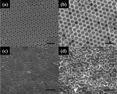
Fig. 1 shows SEM images of the hcp MCCT (a) and resulting cobalt nanoarray films with different morphologies (b–d). It can be clearly seen that an ordered cobalt nanoarray with a hexagonal close-packed arrangement was obtained after removing the hcp MCCT (Fig. 1b, c). The morphologies of the arrays are very sensitive to the deposition time. In general, a nanopore array (Fig. 1b) is formed for deposition times up to 30 min and the size of the pores can be adjusted by the diameter of PS spheres and deposition time. When the deposition time is increased to 60 min, the thickness of the deposited film is larger than the diameter of PS sphere, the top surface of the PS spheres are covered with cobalt film and a dome array formed, as shown in Fig. 1c, but not a hollow sphere array that we anticipated. A flakelet-like film was formed upon further increasing the deposition time (120 min), as shown in Fig. 1d. Therefore, the deposition time should be accurately controlled in the experiments to obtain ordered nanoarrays with different morphologies. | ||
| Fig. 1 FESEM images of PS monolayer colloidal crystal template (a) and cobalt nanoarray films synthesized via template-assisted electrodeposition (b–d). The deposition time is (b) 30, (c) 60 and (d) 120 min, respectively. The scale bars are 2 μm in (a), (b) and (d), and 5 μm in (c). | ||
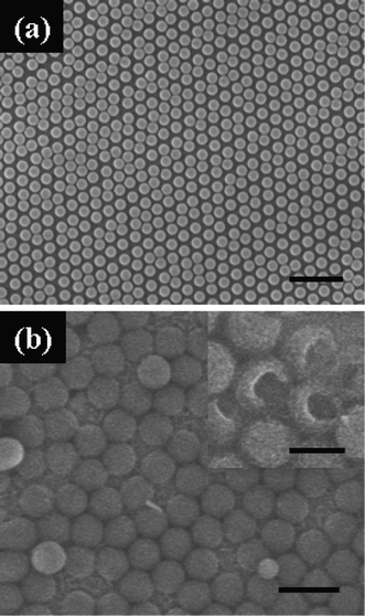
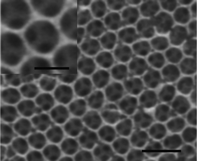
Fig. 2 shows SEM images of the ncp MCCT (a) and the cobalt nanoarrays fabricated on the ncp MCCT (b). The deposition time was 60 min and the deposition current was 0.2 mA cm−2. It can be seen that the spheres are arranged in a ncp manner and the distance between the spheres is about 100 nm (Fig. 2a). Sphere arrays can be obtained on the ncp colloidal monolayer template and the arrays retain the arrangement of the sacrificed template, as shown in Fig. 2b. Spheres with hollow structure can be confirmed by inverting the spheres with ultrasonic cleaning (inset of Fig. 2b). The diameter and the shell thickness of the cobalt spheres were about 1 μm and 20 nm, respectively. Such hollow structures are advantageous for potential applications in catalysis, drug delivery and release, and in advanced optoelectronic devices. Moreover, use of double layer colloidal crystal template led to the synthesis of a mesh array by the electrodeposition procedure, as shown in Fig. 3. The deposition parameters used were the same as for the hollow sphere arrays above. It can be clearly seen that the mesh arrays consisted of two-layer pore arrays with each layer showing an ordered arrangement. From the inset of Fig. 3, we also can see that the triangle junctions of two layers are connected with pillar-like protuberances, which strengthen the mesh arrays. In addition, the magnetic properties of the mesh array may be dominated by their special structure, as discussed below.
 | ||
| Fig. 2 FESEM images of the non-close-packed PS monolayer template (a) and the hollow sphere array via electrodeposition on the non-close-packed template (b). The inset of (b) shows partly broken spheres. The scale bars are 5 μm in (a), 2 μm in (b) and 1 μm in the inset of (b). | ||
 | ||
| Fig. 3 FESEM images of mesh arrays via electrodeposition on a double-layer PS template. The inset shows a magnified image of a single mesh. The scale bar is 2 μm (1 μm in the inset). | ||
In general, cobalt nanoarray films grow from the bottom up during the electrodeposition and the thickness of the films (H) increase with the deposition time. Therefore, the morphology of the array films depend on the deposition time. First, nucleation sites form and grow on the ITO substrate, and interstitial spaces between colloidal spheres are filled with the cobalt film, leading to the formation of a nanopore array (Fig. 1b). When H reaches close to the diameter of the PS spheres with increasing deposition time, dome arrays are obtained based on the previous pore arrays (Fig. 1c). Upon further deposition, flakelet-like films are obtained without limitations imposed by the template (Fig. 1d). It is well known that metal films show preferential growth direction during the electrodeposition process, as reported in ref. 6. Such preferential growth along PS sphere surfaces of the films can be accelerated in the ncp template, thus resulting in a hollow sphere array. In the case of double layer template, the interstitial spaces of the bottom layer was first filled and the top layer film will grow in the interstitial spaces of the top layer MCCT based on the bottom layer, leading to a double layer pore array connected with pillar-like protuberances.
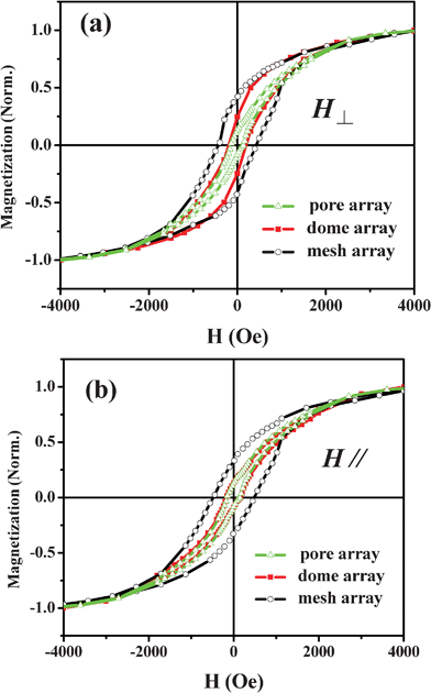
Fig. 4 shows the dependence of magnetic properties on the nanoarray morphology. With the applied magnetic field perpendicular to the surface of the substrate, the coercivities of the pore array and dome array are 150 and 180 Oe with squareness of 0.13 and 0.24, respectively. However, the mesh array exhibits a higher coercivity of 450 Oe and squareness of 0.42, compared with the pore and the dome arrays. The coercivities of the pore, dome and mesh array are 140, 145 and 430 Oe and their squareness are 0.13, 0.13 and 0.33, respectively, for an applied field parallel to the film surface. The magnetic properties of hollow sphere array are similar to the pore array and are not shown.
 | ||
| Fig. 4 Morphology dependent magnetic properties of cobalt nanoarrays at room temperature. The applied magnetic fields are perpendicular (a) and parallel (b) to the surface of the samples. | ||
The mesh array exhibits the highest coercivity and squareness due to the special pillar-like structure perpendicular to the substrate, as mentioned above. Therefore, the magnetic properties of the mesh array are dominated by magnetic shape anisotropy energy, which is different from the pore and hollow sphere arrays in the two different measurement modes. It is noted that the squareness of the dome array also shows magnetic anisotropy, which decreases from 0.24 (perpendicular mode) to 0.13 (parallel mode). In fact, the formation of the dome array is based on the bottom pore array and the pore array grows along the direction perpendicular to the substrate due to the confinement of the MCCT during the electrodeposition process, thus its magnetic properties are similar to compound structure nanofilms. In general, the coercivities and squareness of all samples decrease in the parallel mode compared with that at the perpendicular mode, which is ascribed to the specific growth direction (from bottom to top) of films in a template, resulting in the difference of magnetic properties in the two measurement modes.
4. Conclusions
In conclusion, cobalt nanoarray films with different morphologies were synthesized by electrodeposition on a PS template. The morphology of the nanoarray films could be easily controlled by deposition time and use of patterned PS templates, which may provide a facile approach to fabricate ferromagnetic nanoarrays with controllable morphologies. The pore and hollow sphere arrays show magnetic properties of ordinary nanofilms without obvious shape effect whereas the magnetic properties of mesh and dome arrays exhibit shape anisotropy due to their special structures.Acknowledgements
This work is supported by the National Natural Science Foundation of China (Grant No. 51001078 and 11104150), the Zhejiang Provincial Natural Science Foundation of China (Grant No. Y4110207 and Y4110547) and the Scientific Research Fund of Zhejiang Provincial Education Department (Y201016611), the Key Natural Science Foundation of the Jiangsu Higher Education Institutions of China (Grant No.10KJA140043 and 08KJA510002).References
- (a) Y. Li, N. Koshizaki and W. P. Cai, Coord. Chem. Rev., 2011, 255, 357 CrossRef CAS; (b) H. Zheng, J. Wang, S. E. Lofland, Z. Ma, L. Mohaddes-Ardabili, T. Zhao, L. Salamanca-Riba, S. R. Shinde, S. B. Ogale, F. Bai, D. Viehland, Y. Jia, D. G. Schlom, M. Wuttig, A. Roytburd and R. Ramesh, Science, 2004, 303, 661 CrossRef CAS.
- R. Skomski, J. Phys.: Condens. Matter, 2003, 15, R841 CrossRef CAS.
- K. M. Ainslie, G. Sharma, M. A. Dyer, C. A. Grimes and M. V. Pishko, Nano Lett., 2005, 5, 1852 CrossRef CAS.
- Y. P. Liu, Z. J. Yan, W. Lan, C. M. Huang and Y. Y. Wang, Appl. Surf. Sci., 2007, 253, 8571 CrossRef CAS.
- (a) H. B. Zeng, W. P. Cai, P. S. Liu, X. X. Xu, H. J. Zhou, C. Klingshirn and H. Kalt, ACS Nano, 2008, 2, 1661 CrossRef CAS; (b) A. S. Thornton, P. Janse, D. A. M. J. Theuns, M. F. Scholten and L. J. Jordaens, Europace, 2006, 8, 225 CrossRef CAS.
- (a) G. T. Duan, W. P. Cai, Y. Y. Luo, Z. G. Li and Y. Lei, J. Phys. Chem. B, 2006, 110, 15729 CrossRef CAS; (b) Y. Li, W. P. Cai, B. Q. Cao, G. T. Duan, F. Q. Sun, C. C. Li and L. C. Jia, Nanotechnology, 2006, 17, 238 CrossRef CAS.
- G. B. Ji, S. L. Tang, B. X. Gu and Y. W. Du, J. Phys. Chem. B, 2004, 108, 8862 CrossRef CAS.
- T. N. Narayanan, M. M. Shaijumon, P. M. Ajayan and M. R. Anantharaman, J. Phys. Chem. C, 2008, 112, 14281 CAS.
- (a) Z. G. Li, W. P. Cai, G. T. Duan, H. B. Zeng and P. S. Liu, J. Nanosci. Nanotechnol., 2009, 9, 2970 CrossRef CAS; (b) Z. G. Li, P. S. Liu, Y. P. Liu, W. P. Chen and G. P. Wang, Nanoscale, 2011, 3, 2743 RSC.
- Y. Li, C. C. Li, S. O. Cho, G. T. Duan and W. P. Cai, Langmuir, 2007, 23, 9802 CrossRef CAS.
- (a) Y. Li, W. P. Cai and G. T. Duan, Chem. Mater., 2008, 20, 615 CrossRef CAS; (b) Y. Li, T. Sasaki, y. Shimizu and N. Koshizaki, Small, 2008, 4, 2286 CrossRef CAS.
- (a) H. B. Zeng, G. T. Duan, Y. Li, S. K. Yang, X. X. Xu and W. P. Cai, Adv. Funct. Mater., 2010, 20, 561 CrossRef CAS; (b) X. H. Xia, J. P. Tu, J. Zhang, J. Y. Xiang, X. L. Wang and X. B. Zhao, ACS Appl. Mater. Interfaces, 2010, 2, 186 CrossRef CAS.
- (a) Z. G. Li, W. P. Cai, P. S. Liu, Q. T. Li and L. J. Zou, J. Phys. Chem. C, 2010, 114, 2300 CrossRef CAS; (b) Z. G. Li, W. P. Cai, S. K. Yang, G. T. Duan and R. Ang, J. Phys. Chem. C, 2008, 112, 1837 CrossRef CAS; (c) Y. Li, T. Sasaki, Y. Shimizu and N. Koshizaki, J. Am. Chem. Soc., 2008, 130, 14755 CrossRef CAS.
- B. J. Y. Tan, C. H. Sow, K. Y. Lim, F. C. Chong, G. L. Chong, A. T. S. Wee and C. K. Ong, J. Phys. Chem. B, 2004, 108, 18575 CrossRef CAS.
- P. Jiang and M. J. Mcfarland, J. Am. Chem. Soc., 2005, 127, 3710 CrossRef CAS.
- X. Yan, J. Yao, G. Lu, X. Li, J. Zhang, K. Han and B. Yang, J. Am. Chem. Soc., 2005, 127, 7688 CrossRef CAS.
Footnote |
| † Equally contributed to this work as co-first authors. |
| This journal is © The Royal Society of Chemistry 2012 |
