Microfibrous entrapment of Ni/Al2O3 for dry reforming of methane: a demonstration on enhancement of carbon resistance and conversion†
Wei
Chen
a,
Wenqian
Sheng
a,
Guofeng
Zhao
a,
Fahai
Cao
b,
Qingsong
Xue
a,
Li
Chen
a and
Yong
Lu
*a
aShanghai Key Laboratory of Green Chemistry and Chemical Process, Department of Chemistry, East China Normal University, Shanghai, 200062, China. E-mail: ylu@chem.edu.cn; Fax: (+86)21-62233424
bCollege of Chemical Engineering, East China University of Science and Technology, Shanghai, 200237, China
First published on 6th March 2012
Abstract
Microfibrous entrapment technology in process intensification was demonstrated in the dry reforming of methane. The 8 μm-copper microfibrous entrapped Ni/Al2O3 (Cu-MFE-Ni/AlO) catalyst, with excellent permeability, provided great heat transfer enhancement, thereby leading to significant improvement of carbon resistance by a thermodynamic route along with visible conversion promotion. For instance, at a temperature of 1073 K, 4-fold reduction of average carbon deposition rate was achieved in the Cu-MFE-Ni/AlO composite bed compared to the packed bed of Ni/AlO.
Concerns about the depletion of petroleum reserves and consideration of the chemical recycling of CO2 to fuels/chemicals have warranted particular attention for the dry reforming of methane (DRM) in recent years.1 DRM can convert both CH4 and CO2 into syngas1–4 that can be processed into liquid fuel, chemicals, or fertilizer agents, and also shows great potential for the applications in solar and nuclear energy storage due to its strong endothermicity (ΔH = 247 kJ mol−1).5
The DRM reaction can proceed efficiently in the presence of transient metal catalysts such as Ni/Al2O3.6 However, the poor effective thermal conductivity of the typical catalysts causes severe intra-bed and intra-particle heat transfer limitations. This not only induces a cold-spot in the reactor bed but also imposes a size restriction on the reactor, since the highly endothermic DRM requires a large amount of heat on the catalyst surface. According to thermodynamic analysis,7 the cold-spot decreases the reactor conversion while favouring carbon deposition especially on the Ni-based catalysts, which has been the major challenge on its way to industrialization. And, because of the thermal effect of this reaction, the size of tubular fixed bed reactors does not exceed 80 mm in diameter.8,9 Whereas a thinner reactor tube packed bed (PB) with smaller catalyst particles is able to achieve a more uniform temperature profile and better temperature control, the larger pressure drop will lead to extra problems such as stability, safety and cost. Several distinguishing methods have been developed to improve the transfer characteristics including fluidized bed,10 monolithic bed,11 and slurry bed.12 All of the methods enjoyed some advantages but suffered some disadvantages.13 Therefore, identifying a robust catalyst structure with a unique combination of high thermal conductivity, excellent reactivity and durability is highly desirable from academic and industrial standpoints.
A new class of microfibrous entrapped catalysts (MFECs) has received growing attention due to the special three-dimensional (3D) network, microfibrous monolithic structure (simple bed packing as traditional packed bed), enhanced heat/mass transfer, and high permeability,13,14 which is promising for the development of high-performance catalysts, especially for strongly endothermic14,15 or exothermic reactions.13,16 Recently, the thermal properties of this structure have been studied deeply.13 As noted, Cu-MFEC provided a 10-fold increase of the inside wall heat transfer coefficient compared to the alumina PB, thereby allowing for a great increase of the reactor size.13
In this study, the microfibrous structure consisting of ∼2.0 vol% of 8 μm diameter Cu-fibers was utilized to entrap ∼27 vol% of 0.15–0.18 mm Ni/Al2O3 (denoted as Ni/AlO) particles (see S1 in the ESI† for detailed preparation, characterization and reaction evaluation including results of the samples). We demonstrated the heat transfer intensification effectiveness of such Cu-microfibrous entrapment for the DRM reaction, arising from its enhanced transfer properties. Computational fluid dynamics (CFD) code FLUENT was employed to simulate the temperature distribution inside the Cu-MFE-Ni/AlO composite bed.
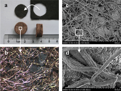
Fig. 1 shows the images of a representative Cu-MFE-Ni/AlO composite. It is clear that the Ni/Al2O3 (Ni-loading of 10.9 wt%; specific surface area of 197 m2 g−1) particles were uniformly entrapped in a well sinter-locked 3D network of copper microfibrous matrix. This entirely open structure with high voidage of 71 vol% provides much higher permeability than PB does (Fig. S2 in S3 of ESI†). Notably, such microfibrous beds can be well preserved even after 250 h DRM running (Fig. 1), indicating the stability of the microfibrous structure. Due to the unique form factor, the MFEC can be made into thin sheets (from submillimeter to several millimeters in thickness) of large area and/or pleated to better control pressure drop and contact efficiency in a manner different from traditionally employed contacting schemes, including packed bed, monolith or woven.13,14 Moreover, the Cu-MFE-Ni/AlO provided a higher surface-to-volume ratio (50 m2 cm−3) compared to the microchannel and honeycomb monoliths.17
 | ||
Fig. 1 Macro- and micro-structure of Cu-MFE-Ni/AlO. (a) Fresh (upper) and used (lower) samples in DRM for 250 h at 1073 K using a gas hourly space velocity (GHSV) of 20![[thin space (1/6-em)]](https://www.rsc.org/images/entities/char_2009.gif) 000 mL h−1 gcat−1 (based on Ni/AlO mass). (b) Optical photograph and (c, d) SEM images of used samples. 000 mL h−1 gcat−1 (based on Ni/AlO mass). (b) Optical photograph and (c, d) SEM images of used samples. | ||
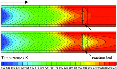
The CFD calculation was used to illustrate thermal conductivity enhancement stemming from such microfibrous entrapment technology. The modelling (Fig. S3) and methods (Fig. S4) are given in S3 of the ESI.† For CFD simulation, 0.51 g of Cu-MFE-Ni/AlO (Cu-fiber: 0.21 g; 0.15–0.18 μm Ni/Al2O3: 0.30 g; void volume: 71 vol%) and 0.58 g of Ni/AlO (0.15–0.18 μm; void volume: 33 vol%) particles were packed in the reactor tube (i.d., 16 mm). According to the experiments, the conversions of methane in both beds were 89% (it was assumed that the conversion of CH4 and CO2 were the same) at 1073 K with a CH4/CO2 (1/1) mixture feed gas flow rate of 100 mL min−1. Note that the Ni/AlO particles packed in the PB were taken from the Cu-MFE-Ni/AlO composite by unlocking the network, making sure that the catalyst particles were the same in both the microfibrous composite bed and the PB. Fig. 2 details the steady-state temperature distributions within the Cu-MFE-Ni/AlO composite bed and the PB bed. For both of them, the cold spot appeared in the upwind-side of the bed where the reaction took place intensively. Whereas the DRM required an equivalent amount of heat on the surface of catalyst particles at equivalent reactor conversion in both beds, our Cu-MFE-Ni/AlO composite bed provided a cold point with temperature reduction much smaller than that of the PB. The temperature at the cold spot in the PB was only about 900 K—109 K lower than that (1009 K) in the Cu-MFE-Ni/AlO bed; and the average bed temperatures of the PB and Cu-MFE-Ni/AlO beds were 964 K and 1039 K. The temperature profiles along the radial direction and reaction rate along the axial direction are shown in Fig. S5 and Fig. S6 in the ESI,† respectively. The temperature difference from reactor wall to central line was about 42 K for Cu-MFE-Ni/AlO, much lower than that of ∼150 K for the PB. As reported, the effective thermal conductivity of copper MFEC is 9.3 times that of porous Al2O3 PB in the radial direction and 2.0 times in the axial direction.13 This is why our Cu-MFE-Ni/AlO composite bed provided a relatively uniform temperature profile compared to the PB.
 | ||
| Fig. 2 Temperature distribution at steady-state inside reaction bed: Cu-MFE-Ni/AlO composite bed (upper); PB (lower). | ||
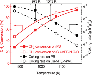
Fig. 3 shows the methane conversion and carbon deposition rate for DRM in both the Cu-MFE-Ni/AlO composite bed and the PB with the same amount of Ni/AlO (taken from Cu-MFE-Ni/AlO) as entrapped in the microfibrous composite bed at various temperatures. The control experiments showed that the Cu-fiber induced very low conversion at equivalent bed volume at or below 1073 (see S1.3 in the ESI†). Not surprisingly, the methane conversion in the Cu-MFE-Ni/AlO composite bed looks as if it was obtained at a temperature of 70 K higher than in the PB. This is in great agreement with the prediction of the foregoing CFD calculation results (e.g., there was ∼75 K difference between their average bed temperatures). For example, when the reactor temperature was set at 1073 K, CH4 conversion in Cu-MFE-Ni/AlO composite bed was 89%, clearly being higher than that of 83% in the PB. Note that the slope of the reactor conversion as a function of temperature for both the Cu-MFE-Ni/AlO composite bed and the PB were quite similar. This observation indicated that the apparent activation energy of each bed was not changed evidently.
 | ||
Fig. 3 CH4 conversion (square) and coking rate (circle) as function of reaction temperature on Cu-MFE-Ni/AlO (hollow) and PB (solid). Reaction conditions: total GHSV = 20![[thin space (1/6-em)]](https://www.rsc.org/images/entities/char_2009.gif) 000 mL h−1 g−1 (based on Ni/AlO mass); p = 1 atm. The average coking rates on all samples were obtained by thermogravimetric analysis after 18 h DRM running. 000 mL h−1 g−1 (based on Ni/AlO mass); p = 1 atm. The average coking rates on all samples were obtained by thermogravimetric analysis after 18 h DRM running. | ||
Besides the enhanced reactor conversion, the microfibrous entrapment technology provided a significant suppression of the carbon deposition on the Ni/AlO catalyst under DRM reaction conditions. As shown in Fig. 3, at a temperature of 1073 K, the average carbon deposition rate in the Cu-MFE-Ni/AlO composite bed was 1.68 × 10⁻³ g g−1 h−1, only 1/5 or less of that (9.05 × 10⁻³ g g−1 h−1) in the PB. Regarding the carbon formation, it has been noted previously that carbon deposition on the Ni/AlO is favourable at low temperatures.7 The PB caused a severe cold spot with a much lower temperature (Fig. 2, Fig. S5, Fig. S6, ESI†) thereby facilitating the carbon deposition.
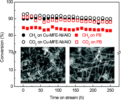
Fig. 4 shows the longer-term testing results for DRM using the Cu-MFE-Ni/AlO composite bed and PB with Ni/AlO particles (the same as those entrapped in the Cu-microfibrous structure) at 1073 K with gas hourly space velocity (GHSV) of 20![[thin space (1/6-em)]](https://www.rsc.org/images/entities/char_2009.gif) 000 mL h−1 gcat−1. Although both the Cu-MFE-Ni/AlO composite bed and the PB showed compatible conversion maintenance throughout the 250 h test, the amount of carbon formed in the microfibrous structured bed was 0.42 g gcat−1, less than half that (0.92 g gcat−1) formed in the PB. The SEM images (inset of Fig. 4) clearly indicate that the formation of whisker-like carbons on the Ni/AlO catalyst particles was definitely suppressed due to the heat transfer intensification benefiting from Cu-microfibrous entrapment technology. Earlier studies have confirmed that the majority of the carbon deposition on the Ni/Al2O3 catalyst is whisker-like carbons,18 which generally do not degrade the activity of catalysts but cause the catalyst to break up, thereby plugging the reactor bed. Indeed, the reactor inlet pressure was observed to gradually increase for the PB after 150 h on the stream but absolutely not for the microfibrous structured bed, even throughout the entire 250 h test. In contrast to the good preservation of our Cu-MFE-Ni/AlO composite in both the microfibrous structure and the catalyst particle entrapped inside (Fig. 1), the catalyst particles in the PB were destroyed mainly owing to severe whisker-like carbon formation after 250 h DRM test (Fig. S7, ESI†). It is thus rational for us to infer that the carbon deposition would be depressed in a thermodynamic way by using the microfibrous entrapment technology which made an almost isothermal profile along the radial direction of the catalytic bed.
000 mL h−1 gcat−1. Although both the Cu-MFE-Ni/AlO composite bed and the PB showed compatible conversion maintenance throughout the 250 h test, the amount of carbon formed in the microfibrous structured bed was 0.42 g gcat−1, less than half that (0.92 g gcat−1) formed in the PB. The SEM images (inset of Fig. 4) clearly indicate that the formation of whisker-like carbons on the Ni/AlO catalyst particles was definitely suppressed due to the heat transfer intensification benefiting from Cu-microfibrous entrapment technology. Earlier studies have confirmed that the majority of the carbon deposition on the Ni/Al2O3 catalyst is whisker-like carbons,18 which generally do not degrade the activity of catalysts but cause the catalyst to break up, thereby plugging the reactor bed. Indeed, the reactor inlet pressure was observed to gradually increase for the PB after 150 h on the stream but absolutely not for the microfibrous structured bed, even throughout the entire 250 h test. In contrast to the good preservation of our Cu-MFE-Ni/AlO composite in both the microfibrous structure and the catalyst particle entrapped inside (Fig. 1), the catalyst particles in the PB were destroyed mainly owing to severe whisker-like carbon formation after 250 h DRM test (Fig. S7, ESI†). It is thus rational for us to infer that the carbon deposition would be depressed in a thermodynamic way by using the microfibrous entrapment technology which made an almost isothermal profile along the radial direction of the catalytic bed.
 | ||
Fig. 4 Longer-term tests of Cu-MFE-Ni/AlO (circle) composite bed and the PB (square) at 1073 K using GHSV of 20![[thin space (1/6-em)]](https://www.rsc.org/images/entities/char_2009.gif) 000 mL h−1 gcat−1. Inset: SEM images of carbon deposition in a composite bed (a) and PB (b). 000 mL h−1 gcat−1. Inset: SEM images of carbon deposition in a composite bed (a) and PB (b). | ||
Conclusions
In summary, a novel microstructured Ni/AlO composite catalyst system for the highly endothermic DRM reaction has been developed by utilizing a sintered-locked microfibrous carrier consisting of ∼2 vol% of 8 μm diameter copper microfibers to entrap ∼27 vol% of 0.15–0.18 mm diameter Ni/AlO catalyst particulates. The microfibrous entrapment provided a combined high heat transfer, robust monolithic structure and unique form factors. By taking these desirable beneficial properties, especially the greatly enhanced heat transfer, significant improvement of the catalyst carbon resistance can be achieved along with an obvious promotion of the steady-state conversion, compared to the PB with the same Ni/AlO catalyst under compatible reaction conditions. We anticipate our assay to be a new point for the DRM, bringing this process a step closer to reality. We emphasize that modification of the entrapped Ni/AlO by using additives such as CeO2 and MgO can further promote its performance especially for the carbon resistance. The work along these lines is in progress in our group.Acknowledgements
This work is supported by the NSF of China (21076083, 20973063), the MOST of China (2011CB201403), the Shanghai Rising-Star Program (10HQ1400800), the Specialized Research Fund for the Doctoral Program of Higher Education (20090076110006), the Fundamental Research Funds for the Central Universities, and the Shanghai Leading Academic Discipline Project (B409).References
- (a) G. A. Olah, A. Goeppert and G. K. Surya Prakash, Beyond oil and gas: the methanol economy, 2nd edn, Wiley-VCH Verlag GmbH & Co. KGaA, Weinheim, 2009 Search PubMed; (b) G. A. Olah, A. Goeppert and G. K. Surya Prakash, J. Org. Chem., 2009, 74, 487 CrossRef CAS.
- M. C. Bradford and M. A. Vannice, Catal. Rev. Sci. Eng., 1999, 41, 1 CAS.
- C. J. Liu, J. Y. Ye, J. J. Jiang and Y. X. Pan, ChemCatChem, 2011, 3, 529 CrossRef CAS.
- N. N. Sun, X. Wen, F. Wang, W. Wei and Y. H. Sun, Energy Environ. Sci., 2010, 3, 366 CAS.
- S. B. Wang and G. Q. M. Lu, Energy Fuels, 1996, 10, 896 CrossRef CAS.
- G. Jones, J. G. Jakobsen, S. S. Shim, J. Kleisa, M. P. Andersson, J. Rossmeisl, F. Abild-Pedersen, T. Bligaard, S. Helvegc, B. Hinnemann, J. R. Rostrup-Nielsen, I. Chorkendorff, J. Sehested and J. K. Nøskov, J. Catal., 2008, 259, 147 CrossRef CAS.
- Y. H. Li, Y. Q. Wang, X. W. Zhang and Z. T. Mi, Int. J. Hydrogen Energy, 2008, 33, 2507 CrossRef CAS.
- D. S. Van Vuuren, CSIR CENG, 1982, 432 Search PubMed.
- J. R. Rostrup-Nielsen, J. Sehested and J. K. Nøskove, Adv. Catal., 2002, 47, 65 CrossRef CAS.
- L. J. Yin, S. Y. Wang, H. L. Lu, J. M. Ding, R. Mostofi and Z. H. Hao, Chem. Eng. J., 2007, 131, 123 CrossRef CAS.
- P. Ciambelli, V. Palma and E. Palo, Catal. Today, 2010, 155, 92 CrossRef CAS.
- R. Krishna and S. T. Sie, Fuel Process. Technol., 2000, 64, 73 CrossRef CAS.
- M. Sheng, H. Y. Yang, D. R. Cahela and B. J. Tatarchuk, J. Catal., 2011, 281, 254 CrossRef CAS.
- Y. Lu, H. Wang, Y. Liu, Q. S. Xue, L. Chen and M. Y. He, Lab Chip, 2007, 7, 133 RSC.
- M. M. Wang, J. F. Li, L. Chen and Y. Lu, Int. J. Hydrogen Energy, 2009, 34, 1710 CrossRef CAS.
- G. F. Zhao, H. Y. Hu, M. M. Deng and Y. Lu, Chem. Commun., 2011, 47, 9642 RSC.
- J. C. Ganley, E. G. Seebauer and R. I. Masel, J. Power Sources, 2004, 137, 53 CrossRef CAS.
- J. Sehested, Catal. Today, 2006, 111, 103 CrossRef CAS.
Footnote |
| † Electronic Supplementary Information (ESI) available: Experimental details on preparation, characterization, and catalytic evaluation; discussion on the equations used for fitting the pressure drop data; FLUENT simulation; Fig. S1 to Fig. S7. See DOI: 10.1039/c2ra20089a/ |
| This journal is © The Royal Society of Chemistry 2012 |
