Fabrication of conducting polypyrrole/β-cyclodextrin nano- and micro-spheres using molecular templates†
Songmin
SHANG
*,
Wei
ZENG
and
Xiao-ming
TAO
Institute of Textiles and Clothing, The Hong Kong Polytechnic University, Hong Kong. E-mail: tcshang@inet.polyu.edu.hk
First published on 7th March 2012
Abstract
An easy synthesis route for conducting polypyrrole/β-cyclodextrin (PPy/β-CD) core-shell spheres has been developed. The conducting spheres were successfully synthesized via a simple stirring/ultrasonic treatment by mixing pyrrole monomer and β-CD in the ethanol/aqueous solution at room temperature. The resultant spheres have a uniform nano- or micro-size and a clear core-shell structure. Further, the morphology and size of the resulting PPy/β-CD spheres depended on the amount of β-CD in the reaction system. A possible formation and size evolution mechanism are proposed.
1. Introduction
The delivery of unique nano- and micro-scale conducting polymers has aroused wide attention due to their potential applications in optical,1 electrical,2 magnetic,3 and biological devices.4–6 The control of the polymer structure in these small dimensions can be achieved by the formation of nanofibers, nanotubes, nanowires, and nanorods although the application of these polymers in energy storage systems,7 sensors8 and electrochemical systems9,10 requires nanosized conducting polymer dots or wires. Recently, special attention has recently been paid to the methods for controlling the size and distribution of polymer spheres, because the size and distribution of nano- and micro-spheres would significantly influence the application of polymer spheres in the advanced devices.11–13 Even though polymer spheres have commonly been produced by template polymerization14 and supramolecular self-assembly,15,16 effective methods controlling the size or structure of polymer spheres have remained a challenging task. For this reason, diversely synthetic ways to prepare nano- and micro-sized polymer spheres have been continuously developed. Many techniques such as layer-by-layer deposition,17in situ polymerization on template particles,18,19 pH-induced micellization of the grafted copolymer,20 core-free-template strategy21 and synthesis in a magnetic ionic liquid22 have been developed to prepare polymer spheres with size ranges from tens of nanometers to a few micrometers. Of the various synthetic strategies, template synthesis is a very powerful tool to fabricate polymer nano- and micro-materials.23 This approach is classified into “hard template synthesis” and “soft template synthesis” by the types of templates used. Generally, porous membranes, inorganic fibers, and a porous solid can be utilized as hard templates, and soft templates include surfactants, block copolymers, polyelectrolytes, liquid crystals, and biomolecules. However, the techniques mentioned above can only be used to prepare hollow spheres with a specific size range. For example, using layer-by-layer deposition, the size of the polymer spheres could be fabricated at a sub-micrometer and micrometer scale but not in the nanometer range.24 This is because the common template (melamine formaldehyde latex particle) used in the process becomes less efficient at the nanometer scale. To prepare polymer nanospheres, smaller templates (e.g. gold nanoparticles17) or other methods (e.g. in situ polymerization on template particles25) have to be used instead. Thus, developing effective strategies to fabricate stable conductive spheres with controllable size in a broad range is still an ongoing challenge.Cyclodextrin (CD), is cyclic oligosaccharides built up from 1,4-glucopyranose units that exhibit a torus-shape structure with a hydrophobic cavity and a hydrophilic exterior. β-CD with seven glucose units is inexpensive among the α, β and γ types of macrocyclic polymers. The most characteristic feature of CDs is the ability to form inclusion compounds with various molecules, especially aromatics. The interior cavity of the molecule provides a relatively hydrophobic environment in which an apolar pollutant can be trapped. Several review articles were devoted to the detailed description of the applications of cyclodextrins.26–29 To obtain optimal polymerization conditions, the properties and nature of the resultant polymer is controlled through CD mediated polymerizations. An effective reason for these is that the inclusion phenomenon leads to significant enhancement in solution properties and influences the reactivity of the guest molecule. Many suitable hydrophobic molecules are thus made completely soluble in an aqueous solution of CD without any chemical modification of the guest involved.30,31 As a polymeric dopant, CDs have been used to synthesized PPy/CD complex32,33 and PPy-conducting polymer wires30,34via chemical and electrochemical polymerization techniques, respectively. However, little attention has been paid to the vital effect of the hydrophobic cavity and hydrophilic exterior of CD for the formation of PPy/CD spheres. Therefore, it is interest to develop a facile synthesis to produce high stability and uniform conducting PPy/CD spheres to meet the requirements for their potential applications.
The purpose of this study is to prepare electrically conductive PPy/β-CD spheres with different size range via the oxidative polymerization of pyrrole in the presence of β-CD. The β-CD plays the roles of both stabilizer and template material, and introduces hydrophobic cavity. The β-CDs cavities were shown to serve as molecular templates, in which pyrrole monomer molecules anchor and initiate the oxidative polymerization of pyrrole. Further, we investigated this specific relationship between the β-CDs and pyrrole interaction, and proposed the mechanism of nanosphere formation. Scanning electronic microscopy (SEM), transmission electron microscopy (TEM), Fourier transform infrared (FT-IR), X-ray diffraction (XRD), and thermogravimetric analysis (TGA) were used to analyze and characterize the conducting polymer nanospheres.
2. Experimental
Materials
The pyrrole monomer (E. Merck, Germany) was distilled at 60–70 mm Hg. The middle fraction of the distillate was collected and transferred into a number of small tubes, and stored in the dark at −10 °C. β-CD and the iron(III) chloride were purchased from Aldrich and used without further purification. Other chemicals used were of analytical regent grade without further purification. Distilled water was used throughout this investigation.Fabrication of conducting PPy/β-CD spheres
The conducting PPy/β-CD spheres were produced by simply adding the pyrrole monomer to various concentrations of β-CD aqueous solution, and adding iron(III) chloride as the oxidant. A representative polymerization for the conductive spheres was as follows: β-CD was added into 100 mL aqueous solution in a 150 mL glass flask under constant stirring for 30 min. Then, 10 mmol pyrrole was injected to the β-CD solution and stirred vigorously for 30 min. Iron(III) chloride (2.28 g, 10 mmol) was dissolved in 100 mL ethanol to prepare an oxidant solution. The two solutions were then carefully transferred to a beaker. During the mixing process, the solution color changed from transparent to dark green, indicating that the polymerization takes place instantaneously. The polymerization was continued for about 24 h at 25 °C. The resulted solution with black precipitate was filtered and washed with the sufficient amount of hot water for one hour to wash out the remaining β-CD and ferric trichloride. Finally, the conducting PPy/β-CD spheres were obtained by drying in a vacuum 70 °C in a vacuum for 48 h.Pure PPy particles were prepared in the similar method but in the absence of β-CD. With the same molar ratio of oxidant to monomer, a conventional solution polymerization was also carried out. The monomer was added into an aqueous solution, then the iron(III) chloride solution was introduced into the solution with continuous stirring, thereafter the polymerization reaction proceeded. The obtained polymer particles were washed with hot water to remove the unreacted chemicals. The PPy particles were dried further at 70 °C in a vacuum for 48 h.
Structural characterization
Morphological analyses of both the conducting PPy/β-CD spheres and the pure PPy particles were performed using an SEM (Phillips XL30 FEG). The sample was mounted on a double-sided adhesive carbon disk and sputter-coated with a thin layer of gold to prevent sample charging problems.TEM images of the samples were recorded on a Phillips CM10 electron microscope at an accelerating voltage of 100 kV. The samples were first dispersed in water. They were then dried down onto carbon-coated copper grids (150 mesh) for TEM observation.
FT-IR spectroscopy studies were carried out on a Bio-Rad Merlin (FTS3000) IR spectrophotometer (30 scans per spectrum at 4 cm−1 resolution). Dried samples were dispersed in KBr and then pressed into a disc.
XRD patterns of the samples were recorded on a Siemens D5005 diffractometer equipped with a Cu-Kα (1.5405 A°) X-ray source. The powders were mounted by double-sided adhesive tape on the plastic sample holders.
TGA was conducted on a Du Pont Thermal Analyst 2100 system, equipped with a TGA 2050 thermogravimetric thermal analyzer under a nitrogen stream with a heating rate of 10 °C min−1.
Electrical characterization
The dry PPy and PPy/β-CD powders were pressed into pellets with a thickness of about 2 mm at 7 ton cm−2 pressures. The conductivity of the pellets was measured at room temperature by the standard four-probe method using a constant DC source (Keithley model 224) and a nanovoltmeter (Keithley, model 181). To reduce the contact resistance between the probes and the film surface, the four contact points were coated with silver paste and dried at 50 °C before taking any electrical measurement.3. Results and discussion
In general, the oxidative polymerization of pyrrole is a function of the monomer and oxidant concentrations, solvent, reaction time and temperature, and the optimum molar ratio of FeCl3/pyrrole for the polymerization of pyrrole by FeCl3 has been suggested to be approximately 2.33![[thin space (1/6-em)]](https://www.rsc.org/images/entities/char_2009.gif) :
:![[thin space (1/6-em)]](https://www.rsc.org/images/entities/char_2009.gif) 1.35,40 However, in this work, to control the growth rate and avoid the aggregation of polypyrrole in the reaction system, the molar ratio of FeCl3/pyrrole (1
1.35,40 However, in this work, to control the growth rate and avoid the aggregation of polypyrrole in the reaction system, the molar ratio of FeCl3/pyrrole (1![[thin space (1/6-em)]](https://www.rsc.org/images/entities/char_2009.gif) :
:![[thin space (1/6-em)]](https://www.rsc.org/images/entities/char_2009.gif) 1) has been applied in obtaining polypyrrole/β-cyclodextrin nano- and micro-spheres (The morphological of the PPy/β-CD composites by using a FeCl3/pyrrole molar ratio of 2.33
1) has been applied in obtaining polypyrrole/β-cyclodextrin nano- and micro-spheres (The morphological of the PPy/β-CD composites by using a FeCl3/pyrrole molar ratio of 2.33![[thin space (1/6-em)]](https://www.rsc.org/images/entities/char_2009.gif) :
:![[thin space (1/6-em)]](https://www.rsc.org/images/entities/char_2009.gif) 1 showed in Fig. S1, ESI †). The overall procedure for producing conducting PPy/β-CD spheres involved several steps, as illustrated in Fig. 1. The first step was the formation of pyrrole/β-CD inclusion complex in aqueous solution. β-CD was chosen as the molecular template because it can include the pyrrole monomer into its hydrophobic cavity, and can act as the molecules anchor and initiate the desired reactions.36 The subsequent step involved the formation of a PPy polymeric shell on the β-CD surface. The β-CD cavity can be isolated in aqueous solution, where pyrrole molecules were captured into the hydrophobic cavities of the β-CD. Polymerization was initiated from the captured pyrrole molecules, forming a kind of initiating center or core. Further polymerization of the pyrrole monomers coated the cores, resulting in a core-shell structure. Therefore, the conducting PPy/β-CD spheres with controllable size, uniform sphere structure have been prepared via a controlled nucleation and growth process.
1 showed in Fig. S1, ESI †). The overall procedure for producing conducting PPy/β-CD spheres involved several steps, as illustrated in Fig. 1. The first step was the formation of pyrrole/β-CD inclusion complex in aqueous solution. β-CD was chosen as the molecular template because it can include the pyrrole monomer into its hydrophobic cavity, and can act as the molecules anchor and initiate the desired reactions.36 The subsequent step involved the formation of a PPy polymeric shell on the β-CD surface. The β-CD cavity can be isolated in aqueous solution, where pyrrole molecules were captured into the hydrophobic cavities of the β-CD. Polymerization was initiated from the captured pyrrole molecules, forming a kind of initiating center or core. Further polymerization of the pyrrole monomers coated the cores, resulting in a core-shell structure. Therefore, the conducting PPy/β-CD spheres with controllable size, uniform sphere structure have been prepared via a controlled nucleation and growth process.
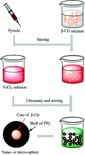 | ||
| Fig. 1 Schematic illustration of the process to fabricate the conducting PPy/β-CD spheres. | ||
During the polymerization of pyrrole, five different amounts of β-CD were used to investigate their effects on the resultant PPy/β-CD morphology. In order to investigate the different formation conditions for PPy/β-CD spheres, morphologies of the PPy/β-CD spheres prepared under different β-CD concentration in the synthetic system were studied. Fig. 2 showed the typical SEM images of the PPy/β-CD composites and the pure PPy particles synthesized at 25 °C for 24 h using a FeCl3/pyrrole molar ratio of 1![[thin space (1/6-em)]](https://www.rsc.org/images/entities/char_2009.gif) :
:![[thin space (1/6-em)]](https://www.rsc.org/images/entities/char_2009.gif) 1. The SEM images clearly show different organization modes. The PPy/β-CD system seems to be a more organized system (Fig. 2(b)–(f)), while the pure PPy particles show irregular structures (Fig. 2(a)). The SEM image of the conducting PPy/β-CD spheres also illustrated that the spheres were uniform and the average diameter was significantly dependent on the amount of β-CD. In the cases with no β-CD, only the PPy particles with irregular structures were obtained. The growth and size evolution of the conducting PPy/β-CD spheres are affected by the amount of β-CD. When the amount of β-CD was 0.5 mmol, Fig. 2(b) revealed that the sample was composed of a large quantity of nanospheres with the size around 200 nm. When the β-CD concentration was 1.0 mmol, as shown in Fig. 2(c), it was seen that the PPy/β-CD spheres obtained were also nanospheres and their average diameter was 400 nm. However, when the amount of β-CD was 1.5 mmol, the sizes of the PPy/β-CD spheres were not uniform, as shown in Fig. 2(d). If the amount of β-CD was increased, the growth rate of the PPy/β-CD spheres was higher because more pyrrole molecules seeded in the β-CD cavities, leading to uncontrollable nanospheres sizes. When the contents of β-CD were increased to 2.0 and 2.5 mmol, the degrees of size dispersion and the uniformities of the prepared conducting PPy/β-CD spheres were remarkably improved, and the sizes of the conducting PPy/β-CD spheres varied from nanospheres to microspheres with an average diameter of 1.0 μm and 1.5 μm respectively (Fig. 2(e) and (f)). The above observations indicated that the β-CD concentration had significant influence on the formation of the PPy/β-CD spheres during polymerization, and can be used to effectively regulate the size of the PPy/β-CD spheres.
1. The SEM images clearly show different organization modes. The PPy/β-CD system seems to be a more organized system (Fig. 2(b)–(f)), while the pure PPy particles show irregular structures (Fig. 2(a)). The SEM image of the conducting PPy/β-CD spheres also illustrated that the spheres were uniform and the average diameter was significantly dependent on the amount of β-CD. In the cases with no β-CD, only the PPy particles with irregular structures were obtained. The growth and size evolution of the conducting PPy/β-CD spheres are affected by the amount of β-CD. When the amount of β-CD was 0.5 mmol, Fig. 2(b) revealed that the sample was composed of a large quantity of nanospheres with the size around 200 nm. When the β-CD concentration was 1.0 mmol, as shown in Fig. 2(c), it was seen that the PPy/β-CD spheres obtained were also nanospheres and their average diameter was 400 nm. However, when the amount of β-CD was 1.5 mmol, the sizes of the PPy/β-CD spheres were not uniform, as shown in Fig. 2(d). If the amount of β-CD was increased, the growth rate of the PPy/β-CD spheres was higher because more pyrrole molecules seeded in the β-CD cavities, leading to uncontrollable nanospheres sizes. When the contents of β-CD were increased to 2.0 and 2.5 mmol, the degrees of size dispersion and the uniformities of the prepared conducting PPy/β-CD spheres were remarkably improved, and the sizes of the conducting PPy/β-CD spheres varied from nanospheres to microspheres with an average diameter of 1.0 μm and 1.5 μm respectively (Fig. 2(e) and (f)). The above observations indicated that the β-CD concentration had significant influence on the formation of the PPy/β-CD spheres during polymerization, and can be used to effectively regulate the size of the PPy/β-CD spheres.
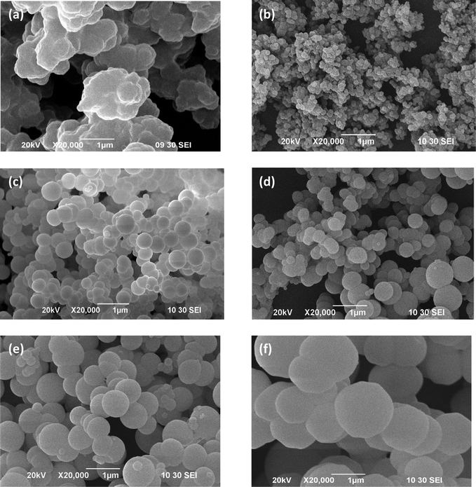 | ||
| Fig. 2 The SEM images of (a) PPy particles, and the prepared conducting PPy/β-CD spheres with different amount of β-CD, (b) 0.5 mmol, (c) 1.0 mmol, (d) 1.5 mmol, (e) 2.0 mmol, (f) 2.5 mmol. | ||
Samples for TEM measurement were dispersed in aqueous solution under sonication. Representative TEM images of the as-prepared conducting PPy/β-CD spheres and pure PPy particles are shown in Fig. 3. Apparently, the amount of β-CD has a strong effect on the size and morphology of the resultant products. Compared with the pure PPy particles prepared in the absence of β-CD, the structures of PPy/β-CD spheres were more oriented and organized than the PPy particles. Moreover, well defined spheres which contained the dark contrast PPy shells and the light contrast β-CD cores were readily observed from the Fig. 3(c), (d) and (e). This indicates that β-CD as a template material played an important role during the polymerization of PPy. When the β-CD concentration is low (0.5 mmol), the polymerization rate is determined by the number of initiating centers or cores, and further polymerization of the pyrrole monomers will lead to uniform nanospheres with sizes around 200 nm. With the increasing the amount of β-CD, several β-CD molecules will form inclusion complexes with the growing PPy chain, forming larger initiating centers or cores. The growth rate of the PPy/β-CD spheres was higher because more pyrrole molecules seeded in the cavities of the β-CDs, resulting to uncontrollable nanospheres sizes. When the amount of β-CD were increased to 2.0 and 2.5 mmol, almost all the β-CD molecules were threaded by a PPy chain to form a larger initiating center or core. The more pyrrole monomers captured into the hydrophobic cavities of the β-CDs—which can provide more active sites—the more the polymerization rate of pyrrole accelerates, resulting in a uniform microsphere with a thicker PPy coating. However, Fig. 3(f) shows that the core structure is not clearly visible within the TEM view field when the amount of β-CD was 2.5 mmol, it was only present as a dark region on the upper right corner of the TEM image. The explanation is that the shell of the PPy/β-CD spheres is too thick and the core structure cannot be detected. As seen in the inset of Fig. 3(f), The SAED patterns indicate that the shell of the PPy/β-CD spheres are nanocrystalline, the images can be considered as the direct evidence that the shell of the fabricated PPy/β-CD spheres were composed of PPy.
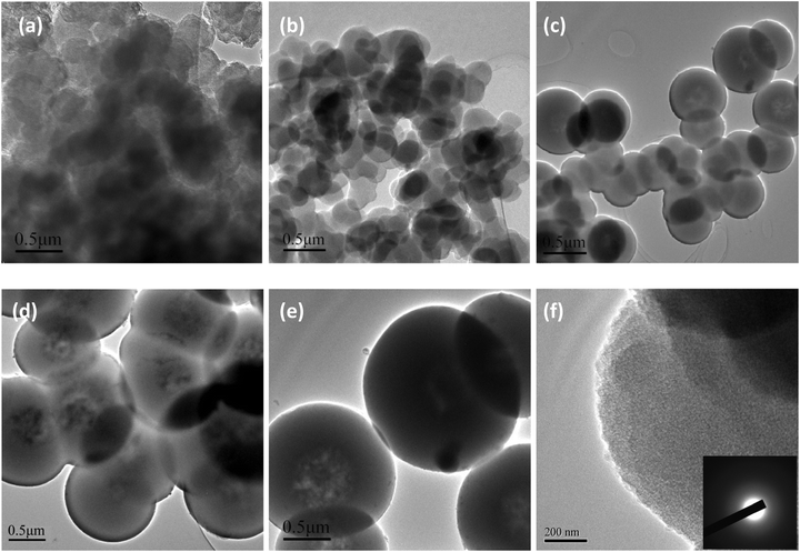 | ||
| Fig. 3 TEM images of (a) PPy particles, and the prepared conducting PPy/β-CD spheres with different amount of β-CD, (b) 0.5 mmol, (c) 1.0 mmol, (d) 1.5 mmol, (e) 2.0 mmol, (f) 2.5 mmol. | ||
The chemical structure of β-CD powder, conducting PPy/β-CD spheres and PPy particles were characterized by FT-IR spectroscopy, as shown in Fig. 4. For PPy (Fig. 4(e)), the typical peaks were observed at 1531 and 1439 cm−1, which were ascribed to the pyrrole ring stretching and the conjugated C–N stretching vibration, respectively. The band at 1051 cm−1 was assigned to a combination C–H in-plane ring bending and the deformation of the five-membered ring. In the case of β-CD (Fig. 4(a)), there were several intensity peaks present in the range of 2800–3100 cm−1 which could be attributed to the C–H stretching vibrations. The range of 600–1500 cm−1 was the fingerprint region of the β-CD. On the spectrum of the conducting PPy/β-CD spheres (Fig. 4(b), (c) and (d)), peaks at 3202 cm−1 (intensive and wide absorption band of O–H stretching vibration), 2962 cm−1 (C–H stretching in saturated hydrocarbon), 1649 cm−1, and 1154 cm−1 (intensive band of ether bond) suggested the existence of β-CD. Also, the peak at 1026 cm−1 suggested the existence of PPy. But the feeble peak at 1026 cm−1 disappeared in the spectrum of PPy/β-CD, which indicated that PPy and β-CD had the stronger coplanar characteristic of the pyrrole units. That means the β-CD affected the formation of the whole structure of PPy in the chemical oxidative polymerization. These results suggest that the structures of PPy/β-CD spheres are affected by the structure of the PPy backbone, and the core of PPy/β-CD spheres can interact with the PPy backbone.
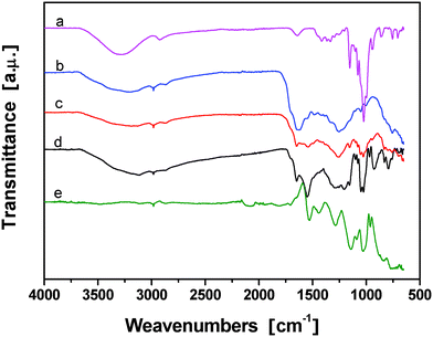 | ||
| Fig. 4 FT-IR spectra of (a) β-CD, and the prepared conducting PPy/β-CD spheres with different amount of β-CD, (b) 1.0 mmol, (c) 2.0 mmol, (d) 2.5 mmol, and (e) PPy particles. | ||
XRD patterns for β-CD powder, PPy/β-CD spheres, and PPy particles were given in Fig. 5. β-CD has many sharply pointed crystallization peaks, especially at 11.8°, 14.2°, and 21.6° (Fig. 5 (a)). Fig. 5(e) shows that the amorphous structure of pure PPy particles and the diffraction pattern of PPy exhibit a broad peak from 15° to 30°. In Fig. 5(b), the broad peak of the PPy/β-CD spheres shows that the broad peak of PPy was obvious and the characteristic peaks of β-CD shifted to 12.3°, 13.3°, and 22°, which indicates that the crystallization peaks of β-CD were affected by the PPy chains. Moreover, compared with Fig. 5(b), (c) and (d), the crystallinity of PPy/β-CD spheres decreased with the increasing amount of β-CD. This suggests that the β-CD molecules were encapsulated by PPy chains.
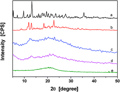 | ||
| Fig. 5 XRD patterns of pure (a) β-CD and the prepared conducting PPy/β-CD spheres with different amount of β-CD, 1.0 mmol (b), 2.0 mmol (c), 2.5 mmol (d), and (e) PPy particles. | ||
To investigate the thermal stability of the conducting PPy/β-CD spheres, the thermal properties of PPy/β-CD spheres were investigated (Fig. 6). Fig. 6(e) shows that the starting decomposition temperature of PPy was 148.4 °C, which was the lowest in the five curves. Because the PPy had some oligomers, such as dimers and trimers, the starting decomposition temperature was very low. However, the total weight loss of PPy was the lowest in the five curves, because the high polymers of PPy had excellent thermal stability. The starting decomposition temperature of β-CD (Fig. 6(a)) was 287 °C, much higher than PPy, but the total weight loss of β-CD was the highest. The thermogravimetric curve of PPy/β-CD (Fig. 6(b), (c) and (d)) had colligated the features of PPy and β-CD, with a higher starting decomposition temperature than that of PPy and a lower total weight loss than that of β-CD. Further, there were two evident decomposition processes during the thermal degradation of the PPy/β-CD spheres, and the thermal stability also increased with the increasing amount of β-CD. Nevertheless, the course of weight loss was obviously slower than that of free β-CD. These results indicated that more β-CD molecules were threaded by PPy chain and stabilized by formation of β-CD/PPy complex with increasing amounts of β-CD.
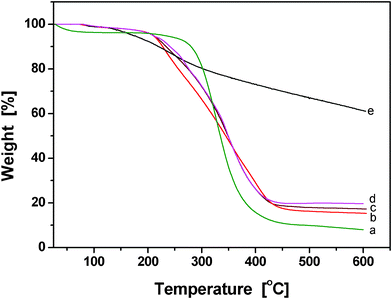 | ||
| Fig. 6 TGA spectra of (a) β-CD, and the prepared conducting PPy/β-CD spheres with different amount of β-CD, (b) 1.0 mmol, (c) 2.0 mmol, (d) 2.5 mmol, and (e) PPy particles. | ||
The above results show that the β-CDs serve as template materials, and PPy subsequently grew on the surface of β-CD molecules by oxidative polymerization. Fig. 7 illustrates the possible reaction mechanism of the oxidation polymerization of pyrrole from the β-CDs' cavity. In the first step, the β-CD molecules formed an inclusion complex with the pyrrole monomers in aqueous solution. The main driving force of complex formation is the release of enthalpy-rich water molecules from the cavity. Water molecules are displaced by pyrrole molecules present in the solution to attain an apolar–apolar association and decrease the β-CD ring strain which results in a more stable lower energy state. On the other side, β-CD might aid transport of the monomer to the loci of polymerization, which correspondingly increases the monomer concentration at the locus of polymerization and thus increases the initial rate of polymerization. Therefore, the polymerization of pyrrole will initiate from the β-CD captured pyrrole molecules and form a kind of initiating center or core. With the growth of the PPy chains, further polymerization of the pyrrole monomers coated the cores; also, several β-CD molecules formed inclusion complexes with the PPy chain to complete the coating of the PPy shell, leading to the formation of conducting PPy/β-CD spheres. With the increasing amount of β-CD, more pyrrole monomers are captured into the hydrophobic cavities of the β-CD which can provide more active sites, which in turn will accelerate polymerization rate of pyrrole, resulting in a thicker PPy coating. Fig. 7 also shows that the size of the conducting PPy/β-CD spheres will increase with the amount of β-CD (n is the repeating unit of PPy-threaded β-CD and directly corresponds to the amount of β-CD). Moreover, β-CD acted as a useful stabilizer to promote a strong interaction between the β-CD and the PPy matrix, the interaction of β-CD and PPy could strengthen the binding forces between polymer chains and finally optimize the configuration of the polymer.
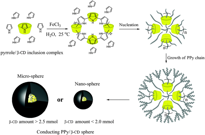 | ||
| Fig. 7 Schematic illustration of the oxidation polymerization of pyrrole from the β-CDs' cavity to form conducting PPy/β-CD nano- and micro-spheres. (n is the repeating unit of PPy-threaded β-CD and directly corresponds to amount of the β-CD.). | ||
The conductivity dependence on the PPy/β-CD conducting spheres polymerized around β-CDs at various molar ratios is plotted in Fig. 8. It shows that the conductivity decreases with the increase in the molar ratio of β-CD. The electrical conductivity decreased from 5.25 to 1.05 S cm−1 with the increase in the amount of β-CD from zero to 2.5 mmol. This indicates that in the PPy chains, the amino groups in the pyrrole rings donate π-electrons to the aromatic networks of the polymer until they are electron deficient. This result implies that β-CD was threaded onto the main chain of PPy macromolecule, not only acting as a template material in the conductive polymer, but also causing torsional twists in the PPy backbone. Therefore, the coplanarity of PPy and β-CD was decreased, which presented a barrier to the intrachain transfer and interchain jumping of the electrons, thereby shortening the conjugation length.
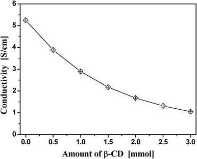 | ||
| Fig. 8 Plot of the conductivity as a function of the amount of β-CD. | ||
To learn more about the mechanism of electrical conductivity, the functional dependence of conductivity on temperature must be determined. Fig. 9 can be used for preliminary characterization. It was seen that the conductivity increased with temperature. This can simply be associated with the contribution of the charge carrier mobility. In this case, the polarons or bipolarons might move with higher diffusion velocity when the temperature increased and thus increase the conductivity.37 In order to get more insight into the transport mechanism, various models were used to fit the data from Fig. 9. For the temperature dependence of the conductivity of conductive nanocomposites, two main mechanisms were suggested: a variable range hopping mechanism38 and a tunneling conduction mechanism.39 These two mechanisms are, respectively, described by the following two equations:
| σ=σ0exp(−A/T1/2) | (1) |
σ∝σ0exp(−A/T[1/(d![[thin space (1/6-em)]](https://www.rsc.org/images/entities/char_2009.gif) + +![[thin space (1/6-em)]](https://www.rsc.org/images/entities/char_2009.gif) 1)]) 1)]) | (2) |
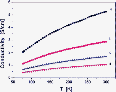 | ||
| Fig. 9 Plots of conductivity as functions of temperatures ranging from 100 to 300 K. (a) PPy particles, and prepared conducting PPy/β-CD spheres with different amounts of β-CD, (b) 1.0 mmol, (c) 2.0 mmol, and (d) 2.5 mmol. | ||
Fig. S2 (See ESI †) shows that the conductivity values when were plotted as Lnσ versus 1/T do not exhibit linear dependency but markedly curved lines. For this reason, eqn (2) is considered where the information on the conduction mechanism and the dimensionality of the process can be determined. The mechanism described Mott's variable range hopping (VRH) model, which describes the transport by hopping of states near the Fermi energy. These states are located at specific states in the energy gap and could act as hopping centers. The hopping probability does not only depend on the energy difference between these localized states but also on the overlap of the electron. The plots of Lnσ versus T[−1/(1![[thin space (1/6-em)]](https://www.rsc.org/images/entities/char_2009.gif) +
+![[thin space (1/6-em)]](https://www.rsc.org/images/entities/char_2009.gif) d)] show that d = 1, or 2 gives straight line curves (Fig. S3 and Fig. S4, ESI †). However, when d = 3, Fig. 10 gives a better linear regression value, it indicates the best fit among the four curves. This point indicates that the transport mechanism in conducting PPy/β-CD spheres corresponds to a 3-D variable range hopping mechanism..
d)] show that d = 1, or 2 gives straight line curves (Fig. S3 and Fig. S4, ESI †). However, when d = 3, Fig. 10 gives a better linear regression value, it indicates the best fit among the four curves. This point indicates that the transport mechanism in conducting PPy/β-CD spheres corresponds to a 3-D variable range hopping mechanism..
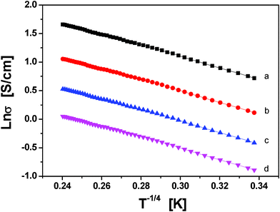 | ||
| Fig. 10 Plots of Lnσ as functions of T−1/4. (a) PPy particles, and the prepared conducting PPy/β-CD spheres with different amounts of β-CD, (b) 1.0 mmol, (c) 2.0 mmol, and (d) 2.5 mmol. | ||
4. Conclusions
The electrically conducting PPy/β-CD spheres with size ranges from 200 nm to 1.5 μm and high stability were successfully fabricated via a one-step polymerization of pyrrole in the presence of β-CD as the molecular template and using iron(III) chloride as an oxidant. The presence of β-CD permits the easy synthesis of conducting PPy/β-CD spheres with controllable size, high stability, and optimizable conductivity. The morphology, structure and properties of the conducting PPy/β-CD spheres were optimized by regulating the amount of β-CD. The electrical transport properties of the conducting PPy/β-CD spheres were studied by using the parallel-plate technique. It was observed that in the temperature range from 75 to 300 K the electrical conductivity decreases with the increases of β-CD amount. The fitting of the experimental temperature dependence data reveals that the Mott's 3-D variable range hopping mechanism is the most suitable mechanism for the conductive behavior of the conducting PPy/β-CD spheres.Acknowledgements
We gratefully acknowledge the grants from the Hong Kong innovation technology funding (ITS/003/09) and The Hong Kong Polytechnic University (A-PK10, and A-PK88) to support this work.References
- C. S. Huang, Y. L. Li, Y. L. Song, Y. J. Li, H. B. Liu and D. B. Zhu, Adv. Mater., 2010, 22, 3532 CAS.
- J. M. Pringle, O. Ngamna, J. Chen, G. G. Wallace, M. Forsyth and D. R. MacFarlane, Synth. Met., 2006, 156, 979–983 CAS.
- S. M. Weekes, F. Y. Ogrin, W. A. Murray and P. S. Keatley, Langmuir, 2007, 23, 1057–1060 CAS.
- A. J. Haes, C. L. Haynes, A. D. McFarland and R. P. Van Duyne, Abstr Pap Am Chem S, 2001, 222, U106–U106 Search PubMed.
- I. Hamad, O. Al-Hanbali, A. C. Hunter, K. J. Rutt, T. L. Andresen and S. M. Moghimi, ACS Nano, 2010, 4, 6629–6638 CAS.
- T. Xia, M. Kovochich, M. Liong, J. I. Zink and A. E. Nel, ACS Nano, 2008, 2, 85–96 CAS.
- D. Kowalski, A. Tighineanu and P. Schmuki, J. Mater. Chem., 2011, 21, 17909–17915 CAS.
- S. J. Choi and S. M. Park, Adv. Mater., 2000, 12, 1547–1549 CAS.
- A. D. W. Carswell, E. A. O'Rear and B. P. Grady, J. Am. Chem. Soc., 2003, 125, 14793–14800 CAS.
- D. Kowalski and P. Schmuki, Chem. Commun., 2010, 46, 8585–8587 CAS.
- R. M. Anisur, J. Shin, H. H. Choi, K. M. Yeo, E. J. Kang and I. S. Lee, J. Mater. Chem., 2010, 20, 10615–10621 CAS.
- M. Q. Chu, F. Wu, Q. Zhang, T. T. Liu, Y. Yu, A. L. Ji, K. Y. Xu, Z. H. Feng and J. Zhu, Nanoscale, 2010, 2, 542–547 CAS.
- J. H. Yang, L. H. Qiu, B. Q. Liu, Y. J. Peng, F. Yan and S. M. Shang, J. Polym. Sci. Pol. Chem., 2011, 49, 4531–4538 CAS.
- D. M. Cheng, H. B. Xia and H. S. O. Chan, Nanotechnology, 2006, 17, 1661–1667 CAS.
- W. Ha, X. W. Meng, Q. A. Li, M. M. Fan, S. L. Peng, L. S. Ding, X. A. Tian, S. Zhang and B. J. Li, Soft Matter, 2011, 7, 1018–1024 CAS.
- J. W. Chung and S. Y. Kwak, Langmuir, 2010, 26, 2418–2423 CAS.
- G. Schneider and G. Decher, Nano Lett., 2004, 4, 1833–1839 CAS.
- L. Li, G. P. Yan, J. Y. Wu, X. H. Yu and Q. Z. Guo, J. Colloid Interface Sci., 2008, 326, 72–75 CAS.
- Y. W. Zhang, J. X. Zhao, M. Jiang and J. Y. Wang, Chem J Chinese U, 2006, 27, 1762–1766 CAS.
- H. Dou, M. Jiang, H. Peng, D. Chen and Y. Hong, Angew. Chem., Int. Ed., 2003, 42, 1516–1519 CAS.
- Y. Hu, X. Q. Jiang, Y. Ding, Q. Chen and C. Z. Yang, Adv. Mater., 2004, 16, 933–937 CAS.
- S. M. Shang, L. Li, X. M. Yang and L. Zheng, J. Colloid Interface Sci., 2009, 333, 415–418 CAS.
- J. Jang, Adv. Polym. Sci., 2006, 199, 189–259 CAS.
- F. Caruso, Top. Curr. Chem., 2003, 227, 145–168 CAS.
- D. Cheng, H. Xia and H. S. Chan, Langmuir, 2004, 20, 9909–9912 CAS.
- T. Loftsson and M. E. Brewster, J. Pharm. Pharmacol., 2010, 62, 1607–1621 CAS.
- S. H. He, W. B. Shi, X. D. Zhang, J. A. Li and Y. M. Huang, Talanta, 2010, 82, 377–383 CAS.
- R. Maeztu, G. Tardajos and G. Gonzalez-Gaitano, J. Phys. Chem. B, 2010, 114, 2798–2806 CAS.
- N. Funasaki, S. Ishikawa and S. Neya, Pure Appl. Chem., 2008, 80, 1511–1524 CAS.
- J. Storsberg, H. Ritter, H. Pielartzik and L. Groenendaal, Adv. Mater., 2000, 12, 567–569 CAS.
- M. K. Rokovic, B. Persi and Z. Mandic, J. Electroanal. Chem., 2010, 643, 46–51 Search PubMed.
- J. T. Feng, W. Yan and J. W. Zhu, Synth. Met., 2010, 160, 939–945 CAS.
- W. Chen, X. B. Wan, N. Xu and G. Xue, Macromolecules, 2003, 36, 276–278 CAS.
- J. Y. Lee and S. M. Park, J. Phys. Chem. B, 1998, 102, 9940–9945 CAS.
- S. P. Armes, Synth. Met., 1987, 20, 365–371 CAS.
- B. A. Rozenberg and R. Tenne, Prog. Polym. Sci., 2008, 33, 40–112 CAS.
- A. A. Zakhidov, Synth. Met., 1991, 43, 3649–3656 CAS.
- H. R. Zeller, Phys. Rev. Lett., 1972, 28, 1452 CAS.
- H. F. Matare, J. Appl. Phys., 1984, 56, 2605–2631 CAS.
- S. M. Shang, X. M. Yang, X. M. Tao and S. S. Lam, Polym. Int., 2010, 59, 204–211 CAS.
Footnote |
| † Electronic Supplementary Information (ESI) available. See DOI: 10.1039/c2ra20118f/ |
| This journal is © The Royal Society of Chemistry 2012 |
