Integrated salinity reduction and water recovery in an osmotic microbial desalination cell†
Bo
Zhang
and
Zhen
He
*
Department of Civil Engineering and Mechanics, University of Wisconsin-Milwaukee, Milwaukee, WI 53211, USA. E-mail: zhenhe@uwm.edu; Fax: +1 414 2296958; Tel: +1 414 2295846
First published on 2nd February 2012
Abstract
The concept of a novel osmotic microbial desalination cell (OsMDC) was presented and experimentally demonstrated. The OsMDC reduced salinity better than forward osmosis because of the combined water flux and electricity generation, and it recovered more water than a conventional microbial desalination cell. The integrated functions of wastewater treatment, water desalination, and water recovery in an OsMDC will create environmental, energy, and economical benefits.
Desalination is an important approach to producing drinking water, especially for some areas where seawater is readily available but freshwater sources are limited. Generally, desalination can be accomplished using thermal and membrane technologies, both of which have been commercialized. Thermal technology uses heat to vaporize water, thereby realizing the separation of salts from water. The common thermal methods are multi-effect distillation, multistage flash distillation, and vapor compression.1 Membrane technology driven by electric energy includes reverse osmosis, membrane distillation, and electrodialysis.2,3 The extensive consumption of energy by desalination technologies is still a drawback and results in high operating costs and water prices. The shortage of clean freshwater sources and the high cost of current desalination processes create a strong need for new desalination technologies with environmental and economic benefits.4
Bioelectrochemical systems have advantages of recovering energy from wastes during water and wastewater treatment.5 Recent development of a microbial catalyzed desalination system—the microbial desalination cell (MDC)—has garnered significant attention and has been studied for different configurations, operations, and functions.6 An MDC takes advantage of microbial metabolism in its anode to generate an electric driving force that stimulates ion migration from its middle chamber into the anode (anions) and the cathode (cations), respectively; as a result, salinity in the middle chamber can be greatly reduced.7–9 Because the driving force of desalination comes from microbial activities (bioelectricity), it is expected that MDC desalination will be a slow process; therefore, it is more appropriate for it to function as a pre-desalination process before conventional desalination units.10 It is known that electricity production is the dominant factor for salt removal in an MDC; however, other factors such as salt diffusion and water osmosis have also been discussed. Water migration into the middle chamber via osmosis is of particular interest, because it will not only dilute saline water but also increase water production.11 Moreover, if the added water is from anolyte (i.e., wastewater), then it will reduce the discharge of wastewater effluent and come with beneficial water reuse. Therefore, an active osmosis is desired to extract water from the anode to dilute saline water and achieve both lower salinity and higher water recovery.
The active water osmosis can be accomplished by the forward osmosis (FO) process, in which an FO membrane allows the free passage of water molecules from a higher water potential to a lower water potential.12,13 The movement of the dissolved solids is mostly rejected by the FO membrane. FO technology has been studied for producing reusable water from wastewater, landfill leachate, and digester centrate.14–17 It is also used for seawater desalination, the pharmaceutical industry, food processing, and the production of osmotic electric power.18–21
Our previous work has successfully integrated FO into a bioelectrochemical system to form a novel osmotic microbial fuel cell (OsMFC).22 The OsMFC can reduce the conductivity of the catholyte (draw solution) by diluting with water flux from the anode, while producing bioelectricity from organic oxidation. Water flux accelerates proton transport, thereby increasing current generation compared with a conventional MFC. The dissolved solids in the catholyte do not obviously change, although its concentration decreases due to the increased water mass.
In this study, we have extended the concept of the OsMFC to MDC technology and created a novel osmotic microbial desalination cell (OsMDC). The anion exchange membrane (AEM) that separates the anode and the middle chamber in a conventional MDC was replaced by an FO membrane in the OsMDC; a cation exchange membrane (CEM) was still used between the cathode and the middle chamber (Fig. 1). With such a change, high-quality water can be extracted from the anode through the FO process to dilute the saline water in the middle chamber, which will also be desalinated via electricity generation, similar to that in a conventional MDC. The feasibility of the OsMDC was examined under different operating conditions and salinities, and it was compared with a conventional MDC in terms of desalination and water production. To ensure that OsMDC performance was not limited by the reactions in the anode and cathode, we oversupplied organic substrates to the anode and used potassium ferricyanide as a terminal electron acceptor in the cathode (more details in the supplementary information†).
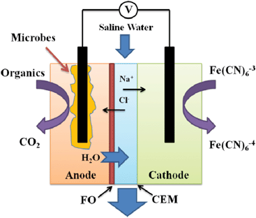 | ||
| Fig. 1 Schematic of an osmotic microbial desalination cell consisting of forward osmosis membrane (FO) and cation exchange membrane (CEM). | ||
First, we examined the OsMDC desalination under the conditions of the open and the closed circuits, respectively. Because no electricity would be produced, the open circuit mimicked an FO process; the closed circuit was operated for high current generation (at a low external resistance of 1 Ω) because more electron movement will remove more salt. In an operating cycle of three days and with an initial salt concentration of 10 g NaCl L−1, both conditions successfully extracted water from the anolyte, with higher water production (in the middle chamber) under the open circuit (Fig. 2A). The water flux at the end of three days was 0.42 ± 0.01 LMH and 0.29 ± 0.04 LMH for the open and the closed circuits, respectively. It should be noted that a higher water flux occurred in the early stage, then it decreased over the time due to the decreased salinity (osmotic pressure). For instance, at the end of the first day, both conditions achieved a similar water flux (0.65 ± 0.05 LMH and 0.69 ± 0.01 LMH). The water flux diluted the saline water and thus reduced its conductivity (salinity) in both conditions. The closed circuit had a much lower conductivity of 6.5 ± 1.1 mS cm−1, about 62% less than the initial conductivity of 17.1 mS cm−1, compared with 11.5 ± 0.2 mS cm−1 under the open circuit, which was about 33% less (Fig. 2B). The difference in salinity reduction between the two conditions suggested that dilution was not the only factor that decreased salinity under the closed circuit, which was also supported by a theoretic estimation of dilution effect on conductivity reduction, assuming that water flux was the only factor under the closed circuit, in which the final conductivity with dilution effect would be 13.1 mS cm−1, about twice the actual final conductivity (Fig. S1†). The additional factor under the closed circuit was electricity generation.
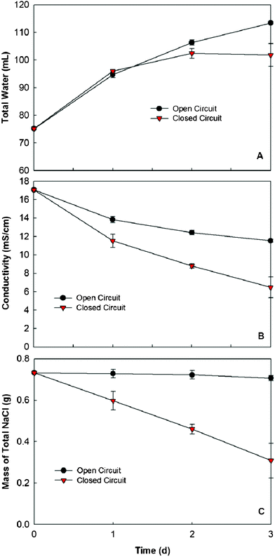 | ||
| Fig. 2 Comparison of the OsMDC performance between the open and closed circuits: (A) water production in the middle chamber, (B) the conductivity of the saline water and (C) the mass of total NaCl calculated from the mass of water and the conductivity. | ||
At an external resistance of 1 Ω, the OsMDC produced an average current of 4.6 mA during three days (Fig. S2†). The electricity production required ion movements across the membranes, which led to desalination. With the information of the total water volume (Fig. 2A) and the conductivity (Fig. 2B), we calculated the mass of total NaCl remaining in the saline water (Fig. 2C). The results clearly showed that significant salt removal (57.8%) occurred with the closed circuit, while the open circuit had a slight decrease (3.4%) in the salt mass after the three-day operation (Fig. 2C). This difference demonstrated that both water dilution and electric current reduced salinity in an OsMDC under the closed circuit, with the electric current playing a major role. Compared with the FO process (the OsMDC under the open circuit), the OsMDC has advantages in removing salt and reducing salinity, which will benefit the downstream desalination when it acts as a pre-desalination unit.
We then investigated the effects of salinities on the OsMDC performance and compared it with a conventional MDC that had the AEM between the anode and the middle chambers. More water was extracted with higher salinity because of higher osmotic pressure (Fig. 3A). With the initial concentration of 20 g NaCl L−1, the water flux decreased from 1.46 ± 0.06 LMH (day one) to 1.01 ± 0.01 LMH (day three). The lowest initial salinity of 5 g L−1 produced 0.15 ± 0.04 LMH in day one and a negative water flux of −0.06 ± 0.05 LMH at the end of three days, because the salinity decreased to a level lower than that of the anolyte/catholyte, and reverse water flux occurred. The conductivity decreased with all three tested salt concentrations (Fig. 3B), and the reduction rate varied between 51.4% (5 g L−1) and 62.0% (10 g L−1). The reduction of salt mass behaved very differently: the OsMDC removed 65.9% and 57.8% of the salt for the initial concentrations of 5 and 10 g L−1, and removed only 17.7% with 20 g L−1 (Fig. 3C). Considering that the current generation with those three initial salt concentrations was similar (data not shown) but water flux was very different, we concluded that the reduction in salinity with the low initial concentrations (5 and 10 g L−1) was mainly due to salt removal by electricity generation; for higher initial concentrations (e.g., 20 g L−1), dilution (water flux) was the major contributor.
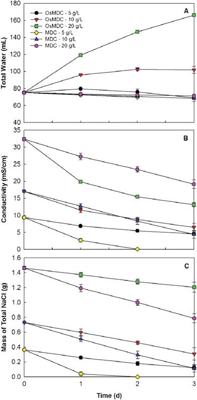 | ||
| Fig. 3 The effect of the initial salinity on the OsMDC performance and the comparison between the OsMDC and the MDC: (A) water volume, (B) conductivity, and (C) salt mass. | ||
The comparison between the OsMDC and the MDC (Fig. 3) indicated the OsMDC was advantageous in extracting water and reducing salinity, but not in removing salt. No water flux into the middle chamber was observed in the MDC with all three initial salt concentrations (Fig. 3A); in fact, slightly negative water flux occurred, possibly because of higher salinity in the catholyte that caused water osmosis from the middle chamber to the cathode chamber. The MDC produced lower final conductivity than the OsMDC when the initial salt concentration was low (5 and 10 g L−1) (Fig. 3B). With 5 g L−1, the MDC decreased the salinity to 0.1 ± 0.0 mS cm−1 in two days. However, at the higher initial salt concentration of 20 g L−1, the MDC generated a final salinity of 19.2 ± 1.3 mS cm−1, higher than 13.1 ± 0.6 mS cm−1 in the OsMDC. The MDC outperformed the OsMDC in salt removal with all three salt concentrations (Fig. 3C). The electricity generation in the MDC was similar to that in the OsMDC (data not shown). The final pH of the saline water in the OsMDC varied between 6.5 and 7.0, lower than 8.0 in the MDC, because the water flux promoted proton transport from the anode into the middle chamber.22
To understand why the OsMDC did not have good salt removal, we analyzed the mass of the individual ions in the saline water. Three ions, including two cations (Na+ and K+) and one anion (Cl−), were detected and quantified (Fig. 4). Initially, there were only two ions, Na+ and Cl−, in the saline water with the equal molar mass (1![[thin space (1/6-em)]](https://www.rsc.org/images/entities/char_2009.gif) :
:![[thin space (1/6-em)]](https://www.rsc.org/images/entities/char_2009.gif) 1). After the three-day operation, the ratio between those two ions became 1
1). After the three-day operation, the ratio between those two ions became 1![[thin space (1/6-em)]](https://www.rsc.org/images/entities/char_2009.gif) :
:![[thin space (1/6-em)]](https://www.rsc.org/images/entities/char_2009.gif) 1.5–1.9, suggesting that sodium ions were removed more quickly than chloride ions. In theory, both ions should be removed at the same rate because the transfer of every electron from the anode electrode to the cathode electrode should drive one sodium ion into the cathode and one chloride ion into the anode. This imbalance in ion removal was likely due to the FO membrane, which retarded chloride ions passing through. Unlike an AEM that only allows anions to move through, an FO membrane does not selectively transport ions and it can reject a wide range of ions.12 As a result, sodium ions moved through the CEM into the cathode driven by electron flow but chloride ions could not transport via the FO membrane at the same step.
1.5–1.9, suggesting that sodium ions were removed more quickly than chloride ions. In theory, both ions should be removed at the same rate because the transfer of every electron from the anode electrode to the cathode electrode should drive one sodium ion into the cathode and one chloride ion into the anode. This imbalance in ion removal was likely due to the FO membrane, which retarded chloride ions passing through. Unlike an AEM that only allows anions to move through, an FO membrane does not selectively transport ions and it can reject a wide range of ions.12 As a result, sodium ions moved through the CEM into the cathode driven by electron flow but chloride ions could not transport via the FO membrane at the same step.
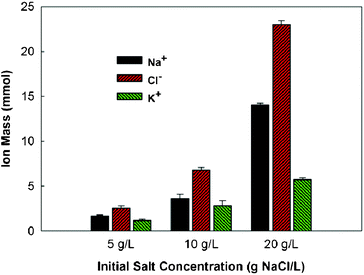 | ||
| Fig. 4 The molar mass of sodium, chloride, and potassium ions in the saline water of the OsMDC after three-day operation. | ||
The imbalanced charge required additional cations into the middle chamber, which could come from both the anode and the cathode chambers. Although the water flux accelerated proton transport from the anode into the middle chamber, the quantity of protons was not sufficient to balance the charge. The intrusion of potassium ions from the cathode contributed to the charge balance, and the molar mass of K+ measured in the saline water makes the ratio between cations and anions close to 1![[thin space (1/6-em)]](https://www.rsc.org/images/entities/char_2009.gif) :
:![[thin space (1/6-em)]](https://www.rsc.org/images/entities/char_2009.gif) 1 (Fig. 4). The catholyte contained a large number of potassium ions from the potassium ferricyanide and potassium phosphate buffer, which facilitated K+ movement; however, ion movement between the anode and the middle chamber is still required for electricity generation. Because the transport of chloride ions and protons was not sufficient to support electricity generation, the movement of cations from the anode into the middle chamber might be possible. One candidate for such a cation is the sodium ion. The anolyte contained sodium ions from sodium acetate, sodium chloride, and sodium bicarbonate. Both water flux and electricity generation could drive sodium ions to leave the anode and migrate into the middle chamber. We did not monitor the sodium concentration in the anode because it (with acetate) was maintained at a high concentration; therefore, the pathway of cation movement from the anode to the middle chamber needs further verification.
1 (Fig. 4). The catholyte contained a large number of potassium ions from the potassium ferricyanide and potassium phosphate buffer, which facilitated K+ movement; however, ion movement between the anode and the middle chamber is still required for electricity generation. Because the transport of chloride ions and protons was not sufficient to support electricity generation, the movement of cations from the anode into the middle chamber might be possible. One candidate for such a cation is the sodium ion. The anolyte contained sodium ions from sodium acetate, sodium chloride, and sodium bicarbonate. Both water flux and electricity generation could drive sodium ions to leave the anode and migrate into the middle chamber. We did not monitor the sodium concentration in the anode because it (with acetate) was maintained at a high concentration; therefore, the pathway of cation movement from the anode to the middle chamber needs further verification.
In general, we believe there are active transport and/or the exchange of cations between the anode/cathode chambers and the middle chamber in the OsMDC, and this movement might have decreased the charge transfer efficiency. For example, at the initial salt concentration of 10 g L−1, the total charge (coulomb) produced in three days was about 1225 C, which is almost enough to remove all the salt (NaCl) that requires 1237 C. The actual removal efficiency (and the charge transfer efficiency) was less than 60%, indicating that some electrons generated in the anode were not used to drive salt out of the middle chamber. It is likely that the cation movement into the middle chamber contributed to current generation, as well as the salt mass.
It seems that the OsMDC will be more suitable for treating high salinity waters because of a stronger water flux for dilution effect. Seawater that comes from natural sources contains a higher salinity (than the saline water tested in this study) and is widely used for desalination. Therefore, we examined the desalination of artificial seawater (prepared with aquarium sea salts) in the OsMDC (Fig. 5). In a cycle of three days, the seawater conductivity decreased from 46.7 mS cm−1 to 17.1 ± 4.4 mS cm−1—more than 60% reduction. The final volume of the seawater was 162.3 ± 1.2 mL, twice the initial volume of 75.1 mL, and the water flux changed from 1.30 ± 0.01 LMH (day one) to 0.96 ± 0.01 LMH (day three). This water flux is slightly lower than the one with 20 g NaCl L−1, possibly due to the complex elements in seawater that could cause more serious membrane fouling than NaCl. We measured the membrane resistance using electrochemical impedance spectroscopy23 and the Bode plots showed that the fouled membrane (after 10-day seawater operation) clearly behaved differently from the new membrane (Fig. S3†). The overall impedance increased and the membrane resistance (after deducting the solution resistance) also increased from 1.9 to 6.0 Ω, indicating the fouling. FO membrane fouling has been a subject of study and chemical and mechanical methods have been developed to restore the membrane function.24,25 Future OsMDC development will take advantage of existing knowledge on membrane fouling and evolve a cleaning method (with fewer effects on the anode microbes) to alleviate fouling conditions.
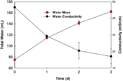 | ||
| Fig. 5 Water recovery and conductivity of the seawater (35 g L−1) in the OsMDC. | ||
These results have collectively demonstrated that the OsMDC could be a promising technology for integrated wastewater treatment, desalination and water reuse, with environmental, energy, and economical benefits. Compared with the FO technology, the OsMDC can convert organics into electric energy and remove salts from saline waters. Compared with the MDC technology, the OsMDC can recover high-quality water from wastewater and reduce salinity through dilution; in addition, according to the manufacturers, the FO membrane in the OsMDC costs less ($30 m−2) than the AEM used in the MDC ($97 m−2), which will greatly reduce the capital investment. Before stepping into practical issues like reactor configuration and scaling up, further investigation is required to understand fundamental issues such as ion transport and membrane fouling.
Acknowledgements
This work was financially supported by a faculty start-up fund at the University of Wisconsin-Milwaukee. We thank Zheng Ge and Qingyun Ping (UW-Milwaukee) for their help with OsMDC operation and impedance analysis, Hydration Technology Innovation for donating FO membranes, and Michelle Schoenecker (UW-Milwaukee) for her assistance with manuscript proofreading.References
- A. D. Khawaji, I. K. Kutubkhanah and J. M. Wie, Desalination, 2008, 221, 47–69 CrossRef CAS.
- C. Charcosset, Desalination, 2009, 245, 214–231 CrossRef CAS.
- M. M. Pendergast and E. M. V. Hoek, Energy Environ. Sci., 2011, 4, 1946–1971 CAS.
- M. A. Shannon, P. W. Bohn, M. Elimelech, J. G. Georgiadis, B. J. Marinas and A. M. Mayes, Nature, 2008, 452, 301–310 CrossRef CAS.
- D. Pant, A. Singh, G. V. Bogaert, S. I. Olsen, P. S. Nigam, L. Diels and K. Vanbroekhoven, RSC Adv., 2012, 2, 1248–1263 RSC.
- X. Cao, X. Huang, P. Liang, K. Xiao, Y. Zhou, X. Zhang and B. E. Logan, Environ. Sci. Technol., 2009, 43, 7148–7152 CrossRef CAS.
- X. Chen, X. Xia, P. Liang, X. Cao, H. Sun and X. Huang, Environ. Sci. Technol., 2011, 45, 2465–2470 CrossRef CAS.
- K. S. Jacobson, D. Drew and Z. He, Bioresour. Technol., 2011, 102, 376–380 CrossRef CAS.
- H. Luo, P. Xu, T. M. Roane, P. E. Jenkins and Z. Ren, Bioresour. Technol., 2012, 105, 60–66 CrossRef CAS.
- M. Mehanna, T. Saito, Y. Jingling, M. A. Hickner, X. Cao, X. Huang and B. E. Logan, Energy Environ. Sci., 2010, 3, 1114–1120 CAS.
- K. S. Jacobson, D. Drew and Z. He, Environ. Sci. Technol., 2011, 45, 4652–4657 CrossRef CAS.
- T. Y. Cath, A. E. Childress and M. Elimelech, J. Membr. Sci., 2006, 281, 70–87 CrossRef CAS.
- T.-S. Chung, S. Zhang, K. Y. Wang, J. Su and M. M. Ling, Desalination, 2011, 287, 78–81 CrossRef.
- T. Y. Cath, S. Gormly, E. G. Beaudry, M. T. Flynn, V. D. Adams and A. E. Childress, J. Membr. Sci., 2005, 257, 85–98 CrossRef CAS.
- T. Y. Cath and A. E. Childress, J. Membr. Sci., 2005, 257, 111–119 CrossRef CAS.
- R. W. Holloway, A. E. Childress, K. E. Dennett and T. Y. Cath, Water Res., 2007, 41, 4005–4014 CrossRef CAS.
- E. R. Cornelissen, D. Harmsen, E. F. Beerendonk, J. J. Qin, H. Oo, K. F. de Korte and J. W. M. N. Kappelhof, Water Sci. Technol., 2011, 63, 1557–1565 CrossRef CAS.
- K. M. Talaat, Artif. Organs, 2009, 33, 1133–1135 CrossRef.
- S. Leob, Desalination, 2002, 143, 115–122 CrossRef.
- E. G. Beaudry and K. A. Lampi, Food Technology, 1990, 44, 121 Search PubMed.
- E. Singer, Nat. Med., 2004, 10, 1267 CrossRef CAS.
- F. Zhang, K. Brastad and Z. He, Environ. Sci. Technol., 2011, 45, 6690–6696 CrossRef CAS.
- J.-S. Park, J.-H. Choi, J.-J. Woo and S.-H. Moon, J. Colloid Interface Sci., 2006, 300, 655–662 CrossRef CAS.
- B. Mi and M. Elimelech, J. Membr. Sci., 2010, 348, 337–345 CrossRef CAS.
- S. Zou, Y. Gu, D. Xiao and C. Y. Tang, J. Membr. Sci., 2011, 366, 356–362 CrossRef CAS.
Footnote |
| † Electronic supplementary information (ESI) available: experimental materials and methods, theoretic estimation of dilution effect on salinity reduction, current generation in the OsMDC and the Bode plots of membrane impedances. See DOI: 10.1039/c2ra20193c |
| This journal is © The Royal Society of Chemistry 2012 |
