DOI:
10.1039/C2RA20310C
(Communication)
RSC Adv., 2012,
2, 3625-3629
A highly efficient colourless sulfur/iodide-based hybrid electrolyte for dye-sensitized solar cells†
Received
20th February 2012
, Accepted 28th February 2012
First published on 28th February 2012
Abstract
A new kind of hybrid electrolyte with S2−/Sx2− and I− was invented, and the new hybrid system was demonstrated to outperform the well-known I−/I3− redox system in DSCs. An efficiency of 9.1% was achieved in our lab under AM 1.5 illumination using the dye N719, considerably higher than the efficiency of 8.0% of the I−/I3−-based electrolyte.
Dye-sensitized solar cells (DSCs) are widely investigated for their high light-to-electricity conversion efficiencies and relatively low production cost since they were significantly improved by Grätzel and O'Regan.1 The electrolyte is one of the essential components of a DSC due to its important role in charge transport and regeneration of the oxidized dye. Iodide/triiodide (I−/I3−) is the most commonly used electrolyte redox couple in high-performance DSCs.2–4 In the traditional electrolyte, the iodine concentration used is relatively high, and polyiodide species, such as I5−, I7− and I9−, may be formed.5 The triiodide and polyiodide species in the electrolyte absorb visible light, which causes an energy loss. Recently, a design of redox mediator containing cobalt (Co) complexes was reported, which enabled the DSC efficiency of 12.3% under 1 sun illumination.6 However, this kind of redox is very dye-selective, and still has a colour problem. Therefore, scientists try to lighten the colour of electrolyte by adding new components or using other redox couples to replace the iodide/triiodide system.7,8 Large particles9 or polymers10 have been added to the electrolyte in order to reduce the colour of the electrolyte. However, the most simple and efficient way is to directly suppress the formation of triiodide and polyiodide species. The removal of I3− can not only make the electrolyte colourless, but also enhance the stability of DSCs by reducing dye degradation. However, the direct reduction of the I3− concentration will cause a loss of overall efficiency. In this work, we have for the first time investigated a highly efficient colourless hybrid electrolyte, which through an intermediate sulfide/polysulfide redox system can inhibit the formation of triiodide and other polyiodides, and at the same time increase the DSC efficiency.
A redox couple consisting of polysulfide (S2−/Sx2−) with an organic tetramethylammonium cation was synthesized by heating the same amount of sulfur and tetramethylammonium sulfide (TMAS) in acetonitrile (details of the synthetic methods are given in the ESI†). Although the exact chemical species and chemical mechanisms involved in a polysulfide electrolyte are very complex and presently poorly understood, it was reported that the polysulfide species (Sx2−, x = 2–5) take the main function of the oxidized component of the redox system in the electrochemical processes.11 In our system, the main species of polysulfide is S52−, which was obtained by recrystallisation, and characterized by elemental analysis (Found/% N: 9.019; C: 31.365; S: 52.015; H: 7.601; Calcd/% N: 9.077; C: 31.135; S: 51.950; H: 7.838).
The redox couple of (S2−/Sx2−), with an organic counter ion, was used in a hybrid system together with I−. As UV-Vis spectra of the electrolytes, shown in Fig. 1, show that the hybrid electrolyte (SI4) with 2.0 mmol L−1 TMAS and S has negligible absorption in the visible region, in contrast to an I−/I3−-based redox electrolyte (I1). The latter displays a strong absorption up to longer wavelength than 500 nm. The reason for this phenomenon is that the polyiodide species in the traditional electrolyte absorbs strongly in visible light region. In the hybrid system the added S2− reduces triiodide and polyiodides and thus maintains the electrolyte transparent and colourless. This significant difference reduces optical losses in the DSCs; a property that is expected to improve the overall light-to-electricity conversion efficiency.
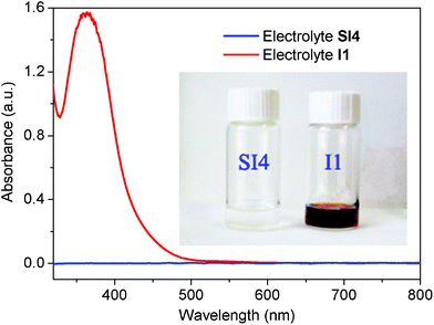 |
| | Fig. 1 Absorption spectra of different electrolytes. Electrolyte I1 composition: 0.60 M 1,2-dimethyl-3-propylimidazolium iodide (DMPII), 0.03 M iodine, 0.053 M lithium iodide, 0.28 M tert-butyl pyridine (TBP) and 0.05 M guanidinium thiocyanate (GuSCN). Electrolyte SI4 composition: 0.60 M DMPII, 0.28 M TBP, 0.068 M lithium iodide, 0.05 M GuSCN, 0.02 M tetramethylammonium sulfide and 0.02 M sulfur. The spectra of both electrolytes were recorded between two pieces of sealed glass, corresponding to the DSC devices. | |
A series of photovoltaic experiments were conducted in order to evaluate the performance of the hybrid electrolyte. In order to optimize the concentration of the TMAS and sulfur, an optimized amount of the other electrolyte components (0.60 M DMPII, 0.28 M TBP, 0.068 M lithium iodide, 0.05 M GuSCN) was used. These concentrations have been obtained for an iodine-based electrolyte and are presumed to be approximately adequate also for the hybrid electrolytes studied in this work. Five hybrid electrolytes were formulated and investigated in the DSC devices (containing the electrolytes SI1–SI5) and compared to our optimized I−/I3− redox electrolyte I1.
Double-layer TiO2 films of 12 μm or 19 μm thickness and a 4 μm scattering layer were employed to support a commonly used organometallic Ru complex dye (N719). On the account of transparency of the hybrid electrolytes a thicker semiconductor film was used in the DSCs. The TiO2 film of 19 μm thickness is the thickest that we can manufacture, which also is the thickness that provides the highest photovoltaic conversion efficiency. The working electrode was attached to the Pt/FTO counter electrode using a 25 μm thick hot-melt film (Surlyn, Solaronix) by heating the system at 120 °C. The details of the fabrication procedures are described in the ESI†.
Under AM 1.5 G illumination (100 mW cm−2), the DSCs containing the electrolyte SI4 shows a photovoltaic open-circuit voltage (Voc), a short-circuit current density (Jsc), and a fill factor (FF) of 796 mV, 16.26 mA cm−2 and 70%, respectively, yielding 9.1% conversion efficiency (η). This is considerably higher than obtained using the I1 electrolyte, arriving at 8.0%. As shown in Fig. 2 and Table 1, the open-circuit voltages of devices which contain a hybrid electrolyte are nearly 100 mV higher than recorded for the purely iodine-based ones. This significant difference can be attributed to two potential effects of the hybrid electrolyte. One effect is caused by the presence of the tetramethylammonium cations, which can prevent charge recombination12 and lead to a higher photovoltage. This effect can be verified in electrochemical impedance spectra of the corresponding devices (see Fig. 3). The other effect can be caused by a different electron transport process. The mechanism for regeneration in an I−/I3− redox electrolyte is a two-step process.13 In the first step of the dye-regeneration process, the oxidized dye and iodide leads to the formation of a diiodide radical (I2−•),14,15 and the overpotential available to drive this reaction is equal to the offset between the highest occupied molecular orbital (HOMO) level of the dye and the I−/I2−• potential. The second step follows when the formed I2−• disproportionates into I3− and I−.
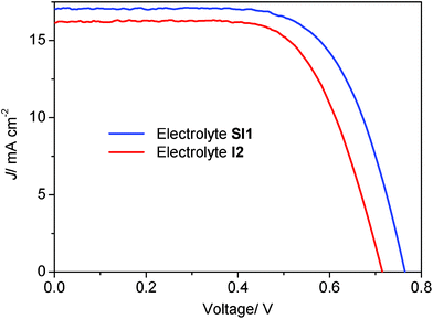 |
| | Fig. 2 Photocurrent density–voltage curves (J–V) of the DSCs containing a hybrid or an iodine-based redox electrolyte. Data are shown for DSCs containing the electrolyte SI1 and I2. The electrolytes SI1 and I2 contain the same amount of LiI. The cells were investigated under air mass 1.5 global (AM 1.5 G) (100 mW cm−2) light irradiation. | |
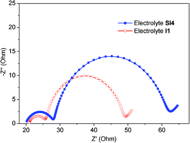 |
| | Fig. 3 Nyquist plots of electrochemical impedance spectra. Impedance was recorded in the frequency range from 10−1 to 106 Hz at room temperature, for the devices containing the electrolytes SI4 and I1. The cells were investigated under AM 1.5 illumination at Voc. The alternate current (AC) amplitude was set at 10 mV. | |
Table 1 Photovoltaic characteristic of DSC devices containing the hybrid and iodine-based electrolytes
| Electrolytea |
SI1 |
SI2 |
SI3 |
SI4 |
SI5 |
I1c |
I2c |
|
Electrolytes SI1 to SI5: contain different amount of TMAS and the other solutes: 0.60 M DMPII, 0.28 M TBP, 0.068 M LiI, 0.05 M GuSCN; electrolyte I1: 0.60 M DMPII, 0.03 M I2, 0.053 M LiI, 0.28 M TBP and 0.05 M GuSCN; electrolyte I2: 0.60 M DMPII, 0.03 M I2, 0.068 M LiI, 0.28 M TBP and 0.05 M GuSCN, all the electrolytes used acetonitrile as solvent.
All of the devices contained a 4 μm scattering layer of 300 nm TiO2 particles on top of the transparent TiO2 layer.
The devices containing I1 was optimized for the pure iodine-based redox couple; the devices based on I2 contains the same amount of LiI and the same thickness of TiO2 as the devices containing the hybrid electrolytes for comparison.
The cells were investigated using a metal mask with an aperture area of 0.159 cm2 and photovoltaic data were recorded under AM 1.5 G illumination.
|
| Film thickness (μm)b |
19 |
19 |
19 |
19 |
19 |
12 |
19 |
| Concentration of TMAS and S (mmol L−1) |
5 |
10 |
15 |
20 |
25 |
0 |
0 |
|
V
oc (mV)d |
765 |
779 |
791 |
796 |
808 |
722 |
716 |
|
J
sc (mA cm−2)d |
17.0 |
17.0 |
16.6 |
16.3 |
16.3 |
15.6 |
16.2 |
| FFd |
0.67 |
0.68 |
0.69 |
0.70 |
0.68 |
0.71 |
0.67 |
|
η (%)d |
8.7 |
9.0 |
9.0 |
9.1 |
9.0 |
8.0 |
7.7 |
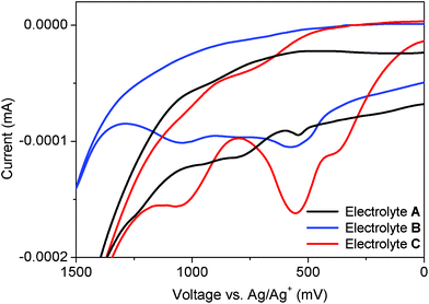
This leads to a large loss in potential equal to the difference between the I−/I2−• and the I−/I3− redox potentials.13 The dye regeneration is most probably the largest single source for loss in potential in the device.16 In the hybrid electrolyte, instead S2− reacts with the I2−• in the second step of dye regeneration, and the process in this way prevents the formation of I3−. This not only renders the hybrid electrolyte colourless, but also reduces the loss in potential, as schematically visualized in Fig. 4. In order to demonstrate this process, a series of electrolytes was tested by cyclic voltammetry (CV). The electrolyte A only contains the redox system S2−/Sx2−, the electrolyte B is a hybrid electrolyte and the electrolyte C corresponds to the electrolyte A but with an over-dose of I2. As shown in Fig. 5, the red curve (C) displays two peaks, of which the right one corresponds to the I−/I3− oxidation (about 370 mV vs. Ag/Ag+).17 A detailed description of the experiments and interpretations can be found in the ESI†. In the corresponding CV curve for the hybrid electrolyte (blue curve), the formation of I3− is suppressed and the peak of I−/I3− (at about 370 mV vs. Ag/Ag+) has disappeared leaving a single peak very close to the S2−/Sx2− reduction (cf. black curve) at 550 mV. This shows that the disproportionation of I2−• is efficiently inhibited in a hybrid electrolyte of this type and gives a feasible explanation to both the gain in optical efficiency and better open-circuit potential observed for the DSC devices.
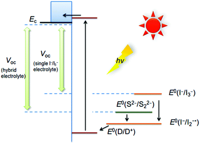 |
| | Fig. 4 Schematic description of electron transfer processes in the I−/I3− electrolyte and hybrid electrolyte. | |
The photocurrent determined under monochromatic illumination [I(λ)] is used to calculate the conversion efficiency from incident photon-to-current data (IPCE) by the equation IPCE(λ) = (I(λ)/Pin(λ))(hc/eλ), where λ is the wavelength, Pin(λ) is the irradiation intensity at λ, h is the Planck constant, c is the speed of light and e is the elementary charge. As shown in Fig. 6, the IPCE value of devices containing the electrolyte SI1 is much higher than that of devices containing the iodine-based electrolyte I2 in the spectral range 300 to 500 nm. This is highly likely the manifestation of the considerably lower light obstruction of the hybrid electrolyte in that spectral region (see Fig. 1).
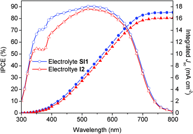 |
| | Fig. 6 Spectral response of the photocurrent of DSCs containing a hybrid electrolyte or an iodine-based electrolyte. The left ordinate shows the IPCE as a function of the wavelength of monochromatic light that impinges on the cell (open symbols). The right ordinate shows the overlap integral of the IPCE with AM 1.5 G solar emission (ASTM G173-03 Reference Spectra derived from SMARTS v. 2.9.2) up to the wavelength shown on the abscissa (filled symbols). Hence, the photocurrent (Jsc) projected on the right ordinate is expected to be generated under the standard reporting solar condition. The devices are described in Fig. 2; the electrolytes SI1 and I2 have been employed (see Table 1). | |
Electrochemical impedance spectroscopy (EIS) was performed in order to get insights into the charge-transfer processes in the different types of DSCs studied in this work. In order to compare the effects of the different types of electrolytes in a proper way, the same thickness of TiO2 films (19 + 4 μm) were used in all devices. The DSCs containing the sensitizing dye N719 was assembled with the I1 electrolyte. A conversion efficiency of 7.5% was recorded together with an open-circuit photovoltage of 690 mV, a short-circuit photocurrent of 15.6 mA cm−2 and a fill factor amounting to 0.70 (see Fig. S7 and Table S1, ESI†). Fig. 3 shows the Nyquist plots of the DSCs containing the electrolytes SI4 and I1, respectively, recorded under AM 1.5 illumination at Voc. Typically, EIS spectra of devices of this type exhibit three more or less overlapping semicircles corresponding to different charge-transport phenomena in a DSC and can be fitted to an electrochemical model18 (equivalent circuit model was shown in Fig. S4†). The middle semicircle is normally assigned to the recombination process at the working electrode, and can be used to extract information on both recombination rate and resistance. The peak frequency of the middle semicircle (ωmax) in the Nyquist plot can be interpreted as an estimate of the reaction rate constant for the recombination (keff).19 As the ωmax value of the central arc was determined to be 15.6 Hz in the device containing SI4 and 30.8 Hz in the device containing I1, the recombination rate constant, keff, in DSCs containing the electrolyte SI4 is about half of that for the corresponding devices containing I1. This clearly indicates that the recombination reaction is inhibited by the hybrid electrolyte system. The suppressed charge recombination is one of the main reasons why the Voc is significantly higher in DSCs containing a hybrid electrolyte instead of the ubiquitous I−/I3− redox system. However, the charge-transfer resistance at the counter-electrode (RCE) of DSCs containing SI4 is 8.6 Ω, which is about two times higher than for DSCs containing I1, 5.4 Ω. It has been shown for organic thiolate/disulfide systems that a platinized counter electrode is a poor catalyst for the reduction of a disulfide to thiolate, resulting in a high charge-transfer resistance. Consequently, the present studies indicate a similar but not as pronounced effect.8,20
| |
| TiO2|N719 + hν →TiO2|N719* → TiO2|N719+ +ecb− | (1) |
| |
| TiO2|N719+ + I− → TiO2 |(N719⋯I) | (2) |
| |
| TiO2|(N719⋯I) + I− → TiO2|N719 + I2−• | (3) |
| |
| S2− + I2−•→ ½S22− + 2I− | (4) |
| |
| x S22− → (x − 1) S2− + Sx+12− | (5) |
| |
| Sx+12− + 2e−→ Sx2− + S2− | (6) |
A possible mechanism is formulated above (1 to 6) in accordance with the experimental results obtained for the hybrid electrolyte systems. After optical excitation of the dye, ultrafast electron injection into the TiO2 conduction band takes place (1). The oxidized dye cation and iodide react and form diiodide radicals (I2−•), which can be observed by nanosecond-laser spectroscopy14 and pseudo-steady-state photoinduced absorption spectroscopy.15 The oxidized dye and iodide first forms a complex (N719⋯I); the formation of such a complex was recently demonstrated by Clifford et al.21 (2). A second iodide ion coordinates, and the complex dissociates into the reduced dye ground state and I2−• (3). Because S2− can efficiently reduce I3− to I−, which is clearly demonstrated by the phenomenon that S2− instantly makes an I−/I3− solution colourless, most likely S2− directly reacts with I2−• forming S22− and I− (4). In solution, only the polysulfides S42− and S52− are known to be stable. S2− and Sx+12− can generate S42− by disproportionation reactions (5).22 At the counter electrode, the polysulfide plays the role as electron acceptor (6).11 In the impedance spectra, the charge-transfer resistance at the counter-electrode (RCE) of the hybrid electrolyte is rather high, which might indicate slow kinetics of the electrochemical reaction (6) at the counter electrode surface.
Conclusions
A new kind of hybrid electrolyte with S2−/Sx2− and I− was applied to DSCs, and the new hybrid system was demonstrated to outperform the well-known I−/I3− redox system. Because of the transparency of the hybrid electrolytes a much thicker TiO2 film (19 μm) can be used, which also enhances DSC performance. An efficiency of 9.1% was achieved in our lab under AM 1.5 illumination (100 mW cm−2) using the N719 sensitizing dye; considerably higher than the recorded efficiency of 8.0% of the corresponding system employing a pure iodine-based electrolyte. The lower light absorption of the hybrid electrolytes also manifests itself in higher Jsc and higher Voc. The hybrid electrolyte represents a new and very promising alternative electrolyte because of its lack of colour, high efficiency and stability. So far, preliminary stability test shows that the devices with hybrid electrolytes appear very stable under illumination in natural light extending over a period of 3 months. Future work will be focused on optimization of the hybrid type of electrolytes, and deeper investigations into the mechanisms of charge transfer and long-term stability.
Since this study, efficiency of greater than 12% has been reported by Grätzel's lab using the same dye, N719, and the same iodide/triiodide electrolyte (only 8.0% was achieved from our lab), the results obtained in this work with the hybrid electrolyte will pave a road to study and develop DSCs with even higher efficiencies than 12%, based on this hybrid electrolyte in the future.
Acknowledgements
We gratefully acknowledge the financial support of this work from China Natural Science Foundation (Grant 21076039, Grant 21120102036), the National Basic Research Program of China (Grant No. 2009CB220009), the Program for Innovative Research Team of Liaoning Province (Grant No. LS2010042), the Ministry of Science and Technology (MOST) (Grant 2001CCA02500), the Swedish Energy Agency, K&A Wallenberg Foundation, and the State Key Laboratory of Fine Chemicals (KF0805).
References
- B. O'Regan and M. Grätzel, Nature, 1991, 353, 737–740 CrossRef CAS
 .
.
- Y. Chiba, A. Islam, Y. Watanabe, R. Komiya, N. Koide and L. Han, Jpn. J. Appl. Phys., 2006, 45, L638 CrossRef CAS
 .
.
- M. K. Nazeeruddin, F. De Angelis, S. Fantacci, A. Selloni, G. Viscardi, P. Liska, S. Ito, B. Takeru and M. Grätzel, J. Am. Chem. Soc., 2005, 127, 16835–16847 CrossRef CAS
 .
.
- C.-Y. Chen, M. Wang, J.-Y. Li, N. Pootrakulchote, L. Alibabaei, C.-H. Ngoc-le, J.-D. Decoppet, J.-H. Tsai, C. Grätzel, C.-G. Wu, S. M. Zakeeruddin and M. Grätzel, ACS Nano, 2009, 3, 3103–3109 CrossRef CAS
 .
.
- G. Boschloo and A. Hagfeldt, Acc. Chem. Res., 2009, 42, 1819–1826 CrossRef CAS
 .
.
- A. Yella, H.-W. Lee, H. N. Tsao, C. Yi, A. K. Chandiran, M. K. Nazeeruddin, E. W.-G. Diau, C.-Y. Yeh, S. M. Zakeeruddin and M. Grätzel, Science, 2011, 334, 629–634 CrossRef CAS
 .
.
- M. Wang, N. Chamberland, L. Breau, J.-E. Moser, R. Humphry-Baker, B. Marsan, S. M. Zakeeruddin and M. Grätzel, Nat. Chem., 2010, 2, 385–389 CrossRef CAS
 .
.
- H. Tian, X. Jiang, Z. Yu, L. Kloo, A. Hagfeldt and L. Sun, Angew. Chem., Int. Ed., 2010, 49, 7328–7331 CrossRef CAS
 .
.
- P. Wang, S. M. Zakeeruddin, I. Exnar and M. Gratzel, Chem. Commun., 2002, 2972–2973 RSC
 .
.
- H. Wang, H. Li, B. Xue, Z. Wang, Q. Meng and L. Chen, J. Am. Chem. Soc., 2005, 127, 6394–6401 CrossRef CAS
 .
.
- Y.-L. Lee and C.-H. Chang, J. Power Sources, 2008, 185, 584–588 CrossRef CAS
 .
.
- E. A. M. Geary, L. J. Yellowlees, L. A. Jack, I. D. H. Oswald, S. Parsons, N. Hirata, J. R. Durrant and N. Robertson, Inorg. Chem., 2004, 44, 242–250 CrossRef
 .
.
- L. M. Peter, Phys. Chem. Chem. Phys., 2007, 9, 2630–2642 RSC
 .
.
- C. Bauer, G. Boschloo, E. Mukhtar and A. Hagfeldt, J. Phys. Chem. B, 2002, 106, 12693–12704 CrossRef CAS
 .
.
- G. Boschloo and A. Hagfeldt, Inorg. Chim. Acta, 2008, 361, 729–734 CrossRef CAS
 .
.
- H. J. Snaith, Adv. Funct. Mater., 2010, 20, 13–19 CrossRef CAS
 .
.
- J. D. Roy-Mayhew, D. J. Bozym, C. Punckt and I. A. Aksay, ACS Nano, 2010, 4, 6203–6211 CrossRef CAS
 .
.
- F. Fabregat-Santiago, G. Garcia-Belmonte, I. Mora-Sero and J. Bisquert, Physical Chemistry Chemical Physics, 2011, 13 Search PubMed
 .
.
- M. Adachi, M. Sakamoto, J. Jiu, Y. Ogata and S. Isoda, J. Phys. Chem. B, 2006, 110, 13872–13880 CrossRef CAS
 .
.
- H. Tian, Z. Yu, A. Hagfeldt, L. Kloo and L. Sun, J. Am. Chem. Soc., 2011, 133, 9413–9422 CrossRef CAS
 .
.
- J. N. Clifford, E. Palomares, M. K. Nazeeruddin, M. Grätzel and J. R. Durrant, The Journal of Physical Chemistry C, 2007, 111, 6561–6567 CrossRef CAS
 .
.
- T. Yang, X. Chen, W. Bin, Q. Chen and Y. Lu, Zhongnan Kuangye Xueyuan Xuebao, 1992, 23, 687–692 CAS
 .
.
Footnote |
| † Electronic Supplementary Information (ESI) available: Details of the synthesis and characterization of TMAS, procedures of fabricating the DSCs, complete assignment and discussion of CV, and other detail data of DSCs mentioned in the paper. See DOI: 10.1039/c2ra20310c/ |
|
| This journal is © The Royal Society of Chemistry 2012 |
Click here to see how this site uses Cookies. View our privacy policy here. 



.
.
.
.
.
.
.
.
.
.
.
.
.
.
.
.
.
.
.
.
.
.
