DOI:
10.1039/C2RA20646C
(Paper)
RSC Adv., 2012,
2, 9130-9134
Sr8MgGd(PO4)7:Eu2+: yellow-emitting phosphor for application in near-ultraviolet-emitting diode based white-light LEDs†
Received
10th April 2012
, Accepted 19th July 2012
First published on 26th July 2012
Abstract
The yellow-emitting phosphor Sr8MgGd(PO4)7:xEu2+ (SMGP:xEu2+) was successfully synthesized by a solid-state reaction and used for the first time to fabricate white light-emitting diodes (LEDs) with excellent color rendering index (CRI). Furthermore, the luminescence properties‚ reflectance spectra and fabricated LEDs were firstly investigated. The excitation and reflectance spectra of this phosphor show broad band excitation and absorption in the 240–470 nm near ultraviolet (NUV) region, indicating its potential application in NUV diode based white-light LEDs. Upon excitation at 385 nm, the Eu2+ doped SMGP phosphors showed strong yellow emission centered at 512 and 606 nm, which could be ascribed to the 4f65d1 → 4f7 transitions of Eu2+. The optimal doping concentration of Eu2+ in SMGP was determined to be 0.01 mol. Non-radiative transitions between the Eu2+ ions in the SMGP host were demonstrated to be attributable to dipole–dipole interactions. A white-light NUV LED was fabricated using a phosphor blend of SMGP:0.01Eu2+ and BAM:Eu2+ pumped by a 385 nm NUV chip, driven by a 350 mA current. The color, chromaticity coordinates (x, y), correlated color temperature (CCT) and Commission Internationale de l'Eclairage (CIE) coordinates can be tuned from yellow ((0.442, 0.481), 3456 K, 75.4) through warm white-light ((0.350, 0.348), 4804 K, 95.6) and eventually to white-light ((0.331, 0.321), 5592 K, 94.1) by weight ratio tuning of the SMGP:0.01Eu2+ and BAM:Eu2+ phosphors, and the luminous efficacy between 9.6 to 7.6 lm W−1. We are currently evaluating the potential applications of SMGP:xEu2+ as a yellow-emitting near-ultraviolet (NUV) convertible phosphor in fabricating warm white-light LEDs with excellent CRI.
Introduction
White light-emitting diodes (LEDs) are considered as a promising technology for next generation solid-state lighting systems because they are environmentally friendly and have several advantages such as long operation lifetime, low energy consumption, and high material stability.1–4 Typically, white-light LED lamps are fabricated using (a) a combination of trichromatic red-, green-, and blue-emitting LED chips;5 (b) blue LED chips combined with a yellow-emitting phosphor (cerium(III) doped yttrium aluminium garnet (YAG:Ce3+));6 or (c) a blend of red-, green-, and blue-emitting phosphors pumped by ultraviolet (UV; 360–380 nm)/near-ultraviolet (NUV; 380–420 nm) chips.7,8 The disadvantages of the combination of trichromatic RGB LEDs system, are that individual colored LEDs respond differently to drive current, operating temperature, dimming, operating time and the controls needed for color consistency add expense. On the other hand, combining YAG:Ce3+ with a blue InGaN chip results in a low color rendering index (CRI) of 75 and a high correlated color temperature (CCT) of 7756 K,9 which can be attributed to the lack of red spectral contribution; consequently, the widespread use of such LED systems is severely restricted. In addition, white-light LEDs can be easily fabricated by integrating red, green, and blue phosphors into a UV/NUV chip, but the disadvantages in this case are the high fabrication cost involved and the poor luminous efficiency resulting from energy reabsorption.
During the past few years, white-light LEDs fabricated using NUV chips with a blend of trichromatic red-, green- and blue-emitting phosphors or a combination of yellow- and blue-emitting phosphors have elicited interest, since the CCT and CRI of these LEDs are much greater than those of conventional white-light LEDs. This is because the CCT, CIE chromaticity coordinates, and CRI values of these NUV chip based LEDs can be tuned by changing the R/G/B or Y/B ratio. Hence, the development of new phosphors that can be effectively excited in the NUV range is a very important prospect that requires prompt attention. Several NUV excitable materials have been identified and investigated for use as the host, for example, Na2CaPO4F:Eu2+,10 Ba2Ca(BO3)2:Ce3+,Mn2+,11 (Sr,Ca)2P2O7:Eu2+,Mn2+,12 Ca2PO4Cl: Eu2+,13 (Ca,Mg,Sr)9Y(PO4)7:Eu2+,Mn2+,14 Ba2ZnS3:Mn2+,15 Ca3Si2O4N2:Eu2+,16 α-Ca2P2O7:Eu2+,Mn2+,17 and Ca3Y(GaO)3(BO3)4:Ce3+,Mn2+,Tb3+.18 To the best of our knowledge, however, the crystal structure and luminescence properties of Eu2+ activated Sr8MgGd(PO4)7 have not yet been reported. In this paper, we report the luminescence properties of the yellow-emitting Sr8MgGd(PO4)7:xEu2+ phosphor and discuss its application in solid-state lighting. Sr8MgGd(PO4)7:xEu2+ is shown to be a suitable phosphor for NUV chip excited warm white-light LEDs.
Experimental
Materials and synthesis
Polycrystalline phosphors with the composition (Sr1−xEux)8MgGd(PO4)7 (SMGP:xEu2+) are prepared by a high-temperature solid-state reaction. Briefly, the constituent raw materials SrCO3 (A. R., 99.9%), MgO (A. R., 99%), Gd2O3 (A. R., 99.99%), (NH4)2HPO4 (Merck, ≥99%), and Eu2O3 (A. R., 99.99%) are weighed in stoichiometric proportions and then sintered for 8 h in a reducing atmosphere at 1200 °C. The products are subsequently cooled to room temperature in the furnace, ground, and pulverized for further measurements.
Materials characterization
The crystal structures of the as-synthesized samples were identified by using powder X-ray diffraction (XRD) analysis with a Bruker AXS D8 advanced automatic diffractometer with Cu-Kα radiation (λ = 1.5418 Å), over the angular range 10° ≤ 2θ ≤ 80°, operating at 40 kV and 40 mA. The photoluminescence (PL) and photoluminescence excitation (PLE) spectra of the samples were analyzed by using a Spex Fluorolog-3 spectrofluorometer equipped with a 450 W Xe light source. The diffuse reflectance (DR) spectra were measured with a Hitachi 3010 double-beam UV-vis spectrometer (Hitachi Co., Tokyo, Japan). The Commission International de l'Eclairage (CIE) chromaticity coordinates for all samples were measured with a Laiko DT-101 color analyzer equipped with a CCD detector (Laiko Co., Tokyo, Japan).
Results and discussion
Crystal structure
Phase identification for the SMGP and SMGP:0.05Eu2+ samples was carried out by measuring the XRD profiles, as shown in Fig. 1. The obtained XRD patterns were consistent with those reported in ICSD file no. 59722.19 XRD analysis was used to determine the chemical purity and phase homogeneity of the SMGP and SMGP:0.05Eu2+ phosphors. The ionic radius of Eu2+ (r = 1.25 Å, coordination number (CN) = 8; r = 1.3 Å, CN = 9) is the closest to that of Sr2+ (r = 1.26 Å, CN = 8; r = 1.31 Å, CN = 9). Therefore, on the basis of the effective ionic radii and charge balance of cations with different CNs, we proposed that Eu2+ should randomly occupy the five Sr2+ sites in the SMGP host structure. The lattice parameters of SMGP and SMGP:0.05Eu2+ (shown in Table 1) were calculated from the experimental XRD profiles using cell refinement software. The lattice parameters of the SMGP powder were as follows: a = 18.0641(34) Å, b = 10.6830(22) Å, c = 18.3754(27) Å, β = 132.930(14)°, and V = 2596.4(6) Å3. Substitution of Sr2+ ions by the relatively smaller Eu2+ ions in the SMGP crystal lattice host was confirmed by the decrease in the lattice parameters of SMGP:0.05Eu2+: a = 18.0476(44) Å, b = 10.6626(27) Å, c = 18.3594(17) Å, β = 132.780(17)°, and V = 2593.1(8) Å3. These results indicated that Eu2+ ions were doped into and entered the SMGP crystal lattice.
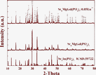 |
| | Fig. 1 Powder XRD patterns of Sr8MgGd(PO4)7 and Sr8MgGd(PO4)7:0.05Eu2+. The Sr9In(PO4)7 standard pattern (ICSD:59722) is shown for reference. | |
Table 1 Rietveld refinement and crystal data of Sr8MgGd(PO4)7 and Sr8MgGd(PO4)7:0.05Eu2+ phosphors
| Formula |
Sr8MgGd(PO4)7 |
(Sr0.95Eu0.05)8MgGd(PO4)7 |
| Formula weight |
1547.418 |
1573.15 |
|
a/Å |
18.0641(34) |
18.0476(44) |
|
b/Å |
10.6830(22) |
10.6626(27) |
|
c/Å |
18.3754(27) |
18.3594(34) |
|
β/° |
132.930(14) |
132.780(17) |
| Volume/Å3 |
2596.4(6) |
2593.1(8) |
Photoluminescence properties
The concentration dependence of the relative PL/PLE intensity of SMGP:xEu2+ (x = 0.005–0.05 mol) is demonstrated in Fig. 2. The emission spectra showed a strong broad yellow emission band in the range 450–800 nm, centered at 512 and 606 nm, typically attributed to the 4f65d1 → 4f7 electronic dipole allowed transitions of Eu2+ ions. The broad asymmetric emission band for SMGP:Eu2+ was attributed to the transition of Eu2+ occupying the five crystallographically distinct Sr2+ sites in the SMGP host. The excitation spectra showed a broad band excitation over the range 300–500 nm, centered at 326 and 369 nm; this excitation band mainly comprised unresolved bands due to the 4f65d1 multiplets of Eu2+ in the excited state. The optimal Eu2+ concentration (x) in SMGP:xEu2+ was decided to be 0.01 mol, since further increase in the concentration resulted in concentration quenching, which in turn caused a decrease in the emission intensity. According to the percolation model,20,21 concentration quenching can occur by (1) interactions between the Eu2+ ions, which result in energy reabsorption among neighboring Eu2+ ions in the rare earth sublattice; or (2) energy transfer from a percolating cluster of Eu2+ ions to killer centers. With an increase in the Eu2+ doping concentration, the excitation edge showed a red shift owing to the enhanced Eu2+–Eu2+ interactions.
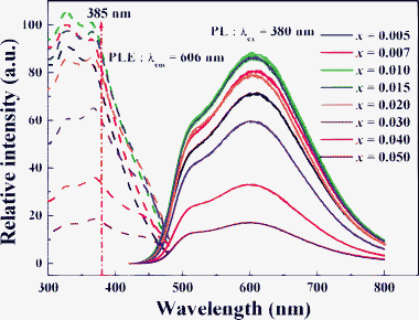 |
| | Fig. 2 Concentration dependence of the relative PL/PLE intensity of Sr8MgGd(PO4)7:xEu2+ (x = 0.005–0.05 mol). | |
Fig. 3 shows the PL intensity of SMGP:xEu2+ as a function of Eu2+ content (x = 0.005–0.05) under 385 nm excitation. The optimal doping concentration was x = 0.01 mol. However, according to the Dexter theory,22 non-radiative transitions between Eu2+ ions occur via electric multipolar interactions. The mechanism of the interaction between Eu2+ ions can be expressed by the following equation:23
| |  | (1) |
where
χ is the activator concentration;
k and
β are constants for each interaction for a given host lattice;
θ values of 6, 8, and 10 correspond to dipole–dipole, dipole–quadrupole, and quadrupole–quadrupole interactions, respectively. The relationship between log(
xEu
2+) and log(
I/
xEu
2+) is shown in the inset of
Fig. 3. The slope of the straight line is −
θ/3, and the value of
θ is approximately 6. The result indicates that non-radiative transitions between Eu
2+ ions occur
via dipole–dipole interactions and lead to concentration quenching of the Eu
2+ ions in the SMGP:
xEu
2+ host, as has been reported previously by our group.
24
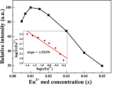 |
| | Fig. 3 PL intensity of Sr8MgGd(PO4)7:xEu2+ as a function of Eu2+ content under 385 nm excitation. The inset shows the relationship between log(xEu2+) and log(I/xEu2+). | |
Electroluminescence properties
White-light LED lamps were fabricated by integrating a mixture of transparent silicone resin and a phosphor blend comprising blue-emitting BaMgAl10O17:Eu2+ (BAM:Eu2+) and yellow-emitting SMGP:0.01Eu2+ in various mixing ratios, on a commodity 385 nm NUV LED chip (AOT, Taiwan, Product No: DC0008CAA, Spec: 385V04C, wavelength peak: 380–385 ± 0.94 nm, chip size: 40 × 40 mil2, forward voltage: 3.8–4.0 ± 0.02 V, power: 30–40 ± 1.66 mW), which was then annealed at 120 °C for 10 h. The LEDs were driven at 350 mA. Fig. 5 shows the electroluminescence (EL) spectra of the lamps. Three emission bands can be clearly seen in Fig. 5a: 383 nm, attributed to the NUV chip; 512 and 606 nm, attributable to the SMGP:0.01Eu2+ phosphor. Fig. 5b–e show four emission bands: 383, attributed to the NUV chip; 454 nm, attributed to BAM:Eu2+; and 512 and 606 nm, attributed to the SMGP:0.01Eu2+ phosphor. Accordingly, the CCT and CRI could be tuned to convert yellow light (3456 K, 75.4, Fig. 5a) into warm white-light (4804 K, 93.9, Fig. 5d) and then to white-light (5592 K, 94.1, Fig. 5e). The CRI gradually increased with the BAM:Eu2+ phosphor mixed ratio, reaching a maximum at 95.6 (Fig. 5d), and then decreased with a further increase in the BAM:Eu2+ mixed ratio. The luminous efficacies of the fabricated white LEDs were measured to be 9.6, 9.3, 9.2, 8.2 and 7.6 lm W−1 for Fig. 5a to Fig. 5e. The lower values of luminous efficacy were due to poor chip efficiency (30–40 ± 1.66 mW). The insets show photographs of the LED lamp packages driven by 350 mA current. The 14 CRIs and average CRI values of white-light LEDs driven by 350 mA current are listed in Table 2. The results indicate that the SMGP:0.01Eu2+/BAM:Eu2+ blends had suitable colors and that the CCT and CRI values were suitable for the application of these blends in white-light NUV LEDs.
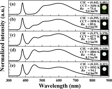 |
| | Fig. 5 EL spectra of white-light LEDs composed of a 385 nm NUV chip and a phosphor blend of blue-emitting BaMgAl10O17:Eu2+ and yellow-emitting Sr8MgGd(PO4)7:0.01Eu2+ in various mixing ratios. | |
Table 2 14 CRIs and average CRI values of white-light LEDs fabricated from blue-emitting BaMgAl10O17:Eu2+ and yellow-emitting Sr8MgGd(PO4)7:0.01Eu2+ with a 385 nm NUV chip driven by 350 mA current
| |
R1 |
R2 |
R3 |
R4 |
R5 |
R6 |
R7 |
R8 |
R9 |
R10 |
R11 |
R12 |
R13 |
R14 |
CRI |
| a |
81 |
82 |
79 |
63 |
78 |
81 |
72 |
67 |
27 |
67 |
59 |
68 |
80 |
91 |
75.4 |
| b |
88 |
93 |
96 |
88 |
88 |
93 |
92 |
79 |
45 |
86 |
88 |
82 |
89 |
98 |
89.6 |
| c |
93 |
98 |
97 |
93 |
94 |
98 |
93 |
85 |
62 |
96 |
94 |
89 |
95 |
98 |
93.9 |
| d |
98 |
98 |
96 |
96 |
97 |
95 |
94 |
91 |
80 |
96 |
98 |
90 |
99 |
98 |
95.6 |
| e |
93 |
93 |
97 |
95 |
92 |
90 |
95 |
98 |
94 |
86 |
92 |
86 |
91 |
98 |
94.1 |
Fig. 6 shows the CIE chromaticity diagram of white-light LEDs with various BAM:Eu2+/SMGP:0.01Eu2+ mixing ratios. By weight ratio tuning, the outputs of the BAM:Eu2+ and SMGP:0.01Eu2+ phosphors were found to systematically emit hues and chromaticity coordinates (x, y) of white-light LEDs from yellow (point a, (0.442, 0.481)) through warm white-light (point c, (0.371, 0.378)) and eventually to the white-light (point e, (0.331, 0.321)) region with increasing BAM:Eu2+ weight ratio. The insets show photographs of the LED packages with a 385 nm NUV chip, driven by 350 mA current. For comparison, YAG:Ce3+ pumped with an InGaN blue chip was considered, and this system was found to emit white-light with chromaticity coordinates, CCT, and CRI of (0.292, 0.325), 7756 K, and 75, respectively.9 The white-light NUV LEDs fabricated in this study (point d) showed higher CRI values (95.6 for SMGP:0.01Eu2+, 75 for YAG:Ce3+) and lower CCT values (4804 K for SMGP:0.01Eu2+, 7756 K for YAG:Ce3+). The results obtained for the LED package demonstrated that SMGP:0.01Eu2+ has potential applications in the white-light NUV LEDs with excellent CRIs.
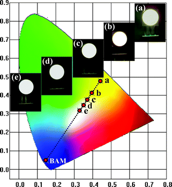 |
| | Fig. 6 CIE chromaticity diagram of white-light LEDs with BaMgAl10O17:Eu2+ and Sr8MgGd(PO4)7:0.01Eu2+ in various mixing ratios. The insets show photographs of the LED packages driven by 350 mA current. | |
Conclusions
A warm white-light LED device with an excellent CRI has been fabricated for the first time using a yellow-emitting phosphor Sr8MgGd(PO4)7:xEu2+, and its luminescence properties, reflectance spectra, and electroluminescence performance have been investigated. Non-radiative transitions between the Eu2+ ions in the Sr8MgGd(PO4)7 host are attributable to dipole–dipole interactions. The reflectance spectra show strong broad absorption in the 240–470 nm (NUV to blue) range, which matches well with those of NUV LED chips. The optical properties of the white-light LEDs (CRI = 95.6 at a CCT of 4804 K, with CIE coordinates of (0.350, 0.348)) are superior to those of conventional white-light LEDs based on YAG:Ce3+ pumped with blue LED chips (CIE = (0.292, 0.325), CRI = 75, CCT = 7756 K).9 Therefore, our novel yellow-emitting Sr8MgGd(PO4)7:xEu2+ phosphor can serve as a key material for phosphor converted warm white-light NUV LEDs.
Acknowledgements
This research was supported by the Industrial Technology Research Institute under contract No. B352A31440 (Y. T. Y.) and No. B301AR4850 (C. H. H.) and in part by the National Science Council of Taiwan under contract No. NSC98-2113-M-009-005-MY3 (T. M. C.).
References
- S. Nakamura, T. Mukai and M. Senoh, Appl. Phys. Lett., 1994, 64, 1687 CrossRef CAS.
- S. Ye, F. Xiao, Y. X. Pan, Y. Y. Ma and Q. Y. Zhang, Mater. Sci. Eng., R, 2010, 71, 1 CrossRef.
- W. B. Im, Y. I. Kim, N. N. Fellows, H. Masui, G. A. Hirata, S. P. DenBaars and R. Seshadri, Appl. Phys. Lett., 2008, 93, 091905 CrossRef.
- T. Nishida, T. Ban and N. Kobayashi, Appl. Phys. Lett., 2003, 82, 3817 CrossRef CAS.
- S. Muthu, F. J. P. Schuurmans and M. D. Pashley, IEEE J. Sel. Top. Quantum Electron., 2002, 8, 333 CrossRef CAS.
- S. Lee and S. Y. Seo, J. Electrochem. Soc., 2002, 149, J85 CrossRef CAS.
- Z. Hao, J. Zhang, X. Zhang, X. Sun, Y. Luo, S. Lu and X. Wang, Appl. Phys. Lett., 2007, 90, 261113 CrossRef.
- J. S. Kim, P. E. Jeon, Y. H. Park, J. C. Choi, H. L. Park, G. C. Kim and T. W. Kim, Appl. Phys. Lett., 2004, 85, 3696 CrossRef CAS.
- C. H. Huang and T. M. Chen, Opt. Express, 2010, 18, 5089 CrossRef CAS.
- C. H. Huang, Y. C. Chen, T. W. Kuo and T. M. Chen, J. Lumin., 2011, 131, 1346 CrossRef CAS.
- C. Guo, L. Luan, Y. Xu, F. Gao and L. Liang, J. Electrochem. Soc., 2008, 155, J310 CrossRef CAS.
- T. G. Kim, Y. S. Kim and S. J. Im, J. Electrochem. Soc., 2009, 156, J203 CrossRef CAS.
- Y. C. Chiu, W. R. Liu, C. K. Chang, C. C. Liao, Y. T. Yeh, S. M. Jang and T. M. Chen, J. Mater. Chem., 2010, 20, 1755 RSC.
- C. H. Huang, P. J. Wu, J. F. Lee and T. M. Chen, J. Mater. Chem., 2011, 21, 10489 RSC.
- P. Thiyagarajan, M. Kottaisamy and M. S. Ramachandra Rao, J. Phys. D: Appl. Phys., 2006, 39, 2701 CrossRef CAS.
- Y. C. Chiu, C. H. Huang, T. J. Lee, W. R. Liu, Y. T. Yeh, S. M. Jang and R. S. Liu, Opt. Express, 2011, 19, A331 CrossRef.
- Z. Hao, J. Zhang, X. Zhang, X. Sun, Y. Luo, S. Lu and X. J. Wang, Appl. Phys. Lett., 2007, 90, 261113 CrossRef.
- C. H. Huang and T. M. Chen, J. Phys. Chem. C, 2011, 115, 2349 CAS.
- ICSD file no. 59722.
- V. A. Vyssotsy, S. B. Gordon, H. L. Frisch and J. M. Hammersley, Phys. Rev., 1961, 123, 1566 CrossRef.
- C. H. Huang and T. M. Chen, Inorg. Chem., 2011, 50, 5725 CrossRef CAS.
- D. L. Dexter, J. Chem. Phys., 1953, 21, 836 CrossRef CAS.
- L. G. Vanuiter, J. Electrochem. Soc., 1967, 114, 1048 CrossRef.
- C. H. Huang, Y. C. Chen, T. M. Chen, T. S. Chan and H. S. Sheu, J. Mater. Chem., 2011, 21, 5645 RSC.
- C. H. Huang, T. M. Chen, W. R. Liu, Y. C. Chiu, Y. T. Yeh and S. M. Jang, ACS Appl. Mater. Interfaces, 2010, 2, 259 CAS.
|
| This journal is © The Royal Society of Chemistry 2012 |
Click here to see how this site uses Cookies. View our privacy policy here. 


