Cationic fluorinated polymer binders for microbial fuel cell cathodes†
Guang
Chen
ab,
Bin
Wei
b,
Bruce E.
Logan
*b and
Michael A.
Hickner
*a
aDepartment of Materials Science and Engineering, The Pennsylvania State University, University Park, PA 16802, United States. E-mail: hickner@matse.psu.edu
bDepartment of Civil and Environmental Engineering, The Pennsylvania State University, University Park, PA 16802, United States. E-mail: bel3@engr.psu.edu
First published on 25th April 2012
Abstract
Fluorinated quaternary ammonium-containing polymers were used as catalyst binders in microbial fuel cell (MFC) cathodes. The performance of the cathodes was examined and compared to NAFION® and other sulfonated aromatic cathode catalyst binders using linear sweep voltammetry (LSV), impedance spectroscopy, and performance tests in single chamber air-cathode MFCs. The cathodes with quaternary ammonium functionalized fluorinated poly(arylene ether) (Q-FPAE) binders showed similar current density and charge transfer resistance (Rct) to cathodes with NAFION® binders. Cathodes containing either of these fluorinated binders exhibited better electrochemical responses than cathodes with sulfonated or quaternary ammonium-functionalized RADEL® poly(sulfone) (S-Radel or Q-Radel) binders. After 19 cycles (19 d), the power densities of all the MFCs declined compared to the initial cycles due to biofouling at the cathode. MFC cathodes with fluorinated polymer binders (1445 mW m−2, Q-FPAE-1.4-H; 1397 mW m−2, Q-FPAE-1.4-Cl; 1277 mW m−2, NAFION®; and 1256 mW m−2, Q-FPAE-1.0-Cl) had better performance than those with non-fluorinated polymer binders (880 mW m−2, S-Radel; 670 mW m−2, Q-Radel). There was a 15% increase in the power density using the Q-FPAE binder with a 40% higher ion exchange capacity (Q-FPAE-1.4-H compared to Q-FPAE-1.0-Cl) after 19 cycles of operation, but there was no effect on the power production due to counter ions in the binder (Cl−vs. HCO3−). The highest-performance cathodes (NAFION® and Q-FPAE binders) had the lowest charge transfer resistances (Rct) in fresh and in fouled cathodes despite the presence of thick biofilms on the surface of the electrodes. These results show that fluorinated binders may decrease the penetration of the biofilm and associated biopolymers into the cathode structure, which helps to combat MFC performance loss over time.
1. Introduction
Microbial fuel cells (MFCs) have been the focus of intensive research over the past decade as promising renewable energy-production and environmental remediation technology.1 Although great progress has been made in increasing MFC performance, further improvements in power densities and reductions in cost could promote widespread use of MFCs, especially in wastewater treatment applications.2,3 Engineering approaches have been used to improve the performance of MFCs through reactor configuration changes and the optimization of component properties, such as anode surface area, cathode construction, separator type, and electrolyte composition.4–7 Among these components, the cathode plays a critical role in MFC performance. Key attributes of the cathode include a porous structure to allow high mass transfer rates of oxygen and protons to the reaction sites, high surface area per volume of the reactor, a high density of catalytic sites for oxygen reduction, a mechanically stable structure for long-term operation, and low cost materials.8–11The active catalyst (platinum, metal porphyrin, activated carbon, or other types of metals or carbons) in the cathode is held in contact with the current collector using a polymer binder.12–14 The binder must allow oxygen and ion transport to the reaction active sites but not reduce electrical contact of the catalyst with the current collector. NAFION®, a hydrophilic cation-conducting polymer bearing sulfonate groups, is commonly used as catalyst binder in MFCs and other types of fuel cells, but its high cost limits its potential for large-scale MFC applications. Thus, inexpensive polymer binders that achieve high cathode performance are needed to construct low-cost MFCs.
The factors that affect binder performance in MFCs are not well understood, and thus there is a need for fundamental knowledge of how binder properties affect power generation in MFCs. Generally, polymer catalyst binders can be hydrophobic and inert within the cathode structure or the polymer binder can be hydrophilic and thus uptake water and participate in charge transfer and oxygen transport to and from the catalyst sites. Hydrophobic, non-ionic poly(tetrafluoroethylene) (PTFE), which is less expensive than NAFION®, was shown to have reduced performance in MFCs compared to NAFION®, likely due to the excluded electrode surface area that is covered by PTFE.12 Saito et al. examined sulfonated and non-sulfonated poly(sulfone)s as cathode catalyst binders.15 In comparison to the hydrophilic sulfonated analogs, the hydrophobic, non-ionic poly(sulfone) RADEL® binder exhibited the best performance in electrochemical tests. Surprisingly, cathodes with increased sulfonate content in the binder displayed depressed electrochemical performance. The reduced performance was likely due to the negatively charged sulfonate groups producing an ion concentration gradient at the catalyst interface which impeded proton transport to the reaction site, or the excess negative charges on the polymer caused unfavorable modifications of the reaction interface. To avoid sulfonated binders, neutral hydrophilic polymer binders without pendant ions, poly(styrene)-b-poly(ethylene oxide) diblock copolymers (PS-b-PEO) and poly(bisphenol A-co-epichlorohydrin) (BAEH) were used in MFC cathodes.16 Cathodes with BAEH binders showed lower initial MFC power densities than those with NAFION® binders, but similar electrochemical performance was obtained after long-term operation (200 cycles). Polymers containing quaternary ammonium groups have been investigated as anion exchange membranes and separators in methanol and hydrogen-fed fuel cells and MFCs,17–20 but there are no studies on their use as catalyst binders in MFCs.
In this work, quaternary ammonium groups were incorporated into low-cost RADEL® poly(sulfone) polymers (Q-Radel) and fluorinated poly(arylene ether)s (Q-FPAE) (Fig. 1) and used as catalyst binders in MFCs. The cationic polymers are not likely to impede ion transport,21 and they could contribute some antifouling function to the cathode structure.22 The performance of these new quaternary ammonium binders was benchmarked against previously tested sulfonated RADEL® (S-Radel) and NAFION® binders. The influence of the Q-FPAE binder composition, including ion exchange capacity (IEC) and counter ion type, was examined using linear sweep voltammetry (LSV) and electrochemical impedance spectroscopy (EIS), and in single-chamber MFC performance tests. The variations in cathode performance for these catalyst polymer binders were related to the details of their chemical structures, which will be helpful in the design of next-generation polymer binders for MFCs.
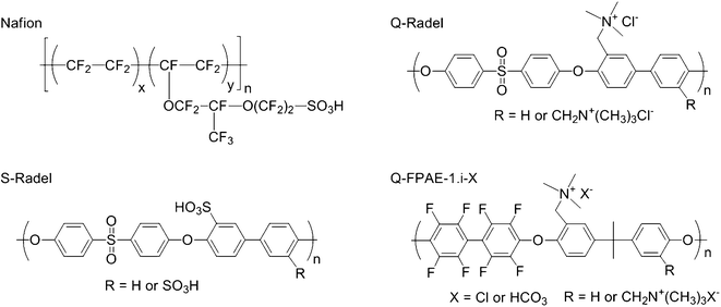 | ||
| Fig. 1 The chemical structures of NAFION®, S-Radel, Q-Radel, and Q-FPAE-1.i-X cathode binders where the general structure of Q-FPAE-1.0 or Q-FPAE-1.4 with Cl− or HCO3− counter anions is shown. | ||
2. Results and discussion
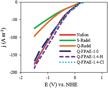
LSV measurements were conducted on abiotic cathodes containing a platinum catalyst with different binders. Substantially different current densities were produced by the cathodes with the different binders in the LSV experiments (Fig. 2). Cathodes with non-fluorinated Radel-based binders had lower current densities than cathodes with fluorinated polymer binders. This difference in the LSV response demonstrated that the structure of the polymer backbone was important in determining the electrochemical performance of the cathode, even though the materials had the same functional pendants, i.e. sulfonate or quaternary ammonium groups. Compared with Q-Radel, the presence of hydrophobic, non-coordinating fluorine atoms in the Q-FPAEs may have allowed increased exposure of the reaction sites for oxygen reduction within the cathode structure. NAFION® also has a fluorinated backbone and it is interesting to note that the non-fluorinated and fluorinated backbone binder polymers tend to fall into two distinct groups. While it is difficult to obtain information on the polymer backbone interaction with the catalytic substrate, the general trends shown in Fig. 2 give us some design guidelines for an effective cathode binder given the high performance of the fluorinated backbone polymers. Based on the LSVs, the quaternary ammonium group does not seem to have a great influence on the binder performance, i.e. NAFION® has a similar performance to Q-FPAE. However, in the MFC experiments discussed later, the quaternary ammonium group in combination with the fluorinated backbone outperformed the control samples over time as they exhibited less power decay. We have considered sulfonated binders in our previous work,15 so the sulfonated fluorinated analogs were not pursued here.Cathode performance of the fluorinated binders was evaluated using EIS (Fig. 3a) where the solution resistance (Rs) was extracted from the high frequency intercept with the real axis, and the charge transfer resistance (Rct) was computed from the first high frequency R–C response in the Nyquist plots.23 The Rct for fluorinated polymer binders (7 Ω for Q-FPAE-1.4-H, 8 Ω for NAFION®, 10 Ω for Q-FPAE-1.4-Cl and 12 Ω for Q-FPAE-1.0-Cl) was lower than that of the cathodes with non-fluorinated binders (15 Ω for Q-Radel and 16 Ω for S-Radel). The solution resistance in all of the EIS tests was between 6 and 7.5 Ω.
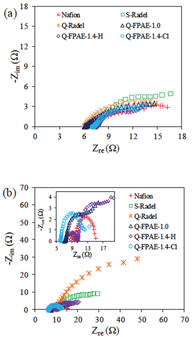 | ||
| Fig. 3 EIS for cathodes with different binders at 0.3 V (vs. NHE) (a): fresh cathode; (b): after 20 cycles. The inset shows EIS curves of NAFION® and fluorinated polymers (200 mM PBS, pH 7.0, 30 °C). | ||
All anodes were started under identical conditions in MFCs with NAFION®-based cathodes. Once the MFCs produced a repeatable performance over several fed-batch cycles (each cycle lasted approximately 1 d), different cathodes were placed in the cells. The maximum voltage produced at a fixed resistance (1000 Ω) decreased appreciably during the initial 5 cycles, then remained relatively constant or slightly decreased over the next 14 cycles (Figure S1†). A decreasing trend in maximum voltage was more significant for the cathodes with non-fluorinated binders than those with fluorinated binders (Fig. 4). Initial performance differences in the first few cycles were due to changes in the cathode performance as the anodes were all fully acclimated.
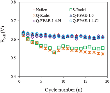 | ||
| Fig. 4 Maximum cell voltage of MFCs with different binders for each cycle. | ||
The decline in cathode performance after 5–10 cycles was likely due to fouling of the cathode structure and catalyst surface by bacteria and exopolymers produced by the bacteria. The extent of the fouling was strongly correlated to the type of cathode binder used. Thick biofilms were visually observed on the surface of the cathodes with fluorinated polymer binders, while the non-fluorinated binder cathodes showed little biofilm on the cathode surfaces after 19 cycles (Figure S2†). The type of ionic group did not seem to have a large influence on the surface biofilm that formed based on visual observations of the surfaces of the cathodes.
For the first cycle with a fresh cathode (Fig. 5a and 5b), all cells showed similar maximum power densities (Pmax), which was unexpected given the differences in the LSV tests. This result indicates that several initial cycles of operation as a “break in” period are necessary for the fresh cathodes to achieve a stable performance. After the 5th cycle (Fig. 5c and 5d), MFC cathodes with fluorinated binders showed significantly higher power densities than cathodes with non-fluorinated polymer binders, consistent with voltages measured over each cycle at a fixed resistance. Compared with the 5th cycle, MFCs with non-fluorinated cathode binders showed reductions in maximum power densities at the 19th cycle (Fig. 5e and 5f), whereas there were minimal decreases in the power densities for MFCs with fluorinated binder-based cathodes (Table 1). Among the fluorinated polymer binders, Q-FPAE-1.4-based reactors showed a higher power density than reactors with Q-FPAE-1.0-Cl-based cathodes.
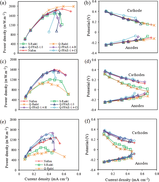 | ||
| Fig. 5 Power density curves and the corresponding cathode and anode potentials (vs. NHE) at (a) the first cycle; (b) the 5th cycle and (c) the 19th cycle with different binders. | ||
| Maximum power density (mW m−2) | Coulombic efficiency (%) | |||||||
|---|---|---|---|---|---|---|---|---|
| Cycle 1 | Cycle 5 | Cycle 19 | Biofilm removed | Cycle 2 | Cycle 6 | Cycle 19 | Biofilm removed | |
| NAFION® | 1875 ± 60 | 1584 ± 43 | 1277 ± 65 | 1518 ± 57 | 22.6 ± 0.3 | 20.0 ± 0.9 | 19.7 ± 0.3 | 19.1 ± 0.6 |
| S-Radel | 1684 ± 78 | 1201 ± 50 | 883 ± 73 | 882 ± 45 | 24.4 ± 5.4 | 26.8 ± 2.0 | 26.9 ± 0.5 | 25.5 ± 1.5 |
| Q-Radel | 1984 ± 77 | 1089 ± 49 | 668 ± 58 | 770 ± 33 | 30.3 ± 0.5 | 25.1 ± 0.6 | 23.2 ± 0.3 | 23.4 ± 0.7 |
| Q-FPAE-1.0 | 1841 ± 82 | 1557 ± 36 | 1256 ± 54 | 1470 ± 45 | 23.4 ± 0.2 | 18.0 ± 0.2 | 19.2 ± 0.4 | 18.8 ± 0.2 |
| Q-FPAE-1.4-H | 1745 ± 66 | 1568 ± 45 | 1445 ± 71 | 1485 ± 51 | 29.5 ± 0.9 | 20.7 ± 4.9 | 20.6 ± 1.1 | 22.6 ± 3.1 |
| Q-FPAE-1.4-Cl | 1720 ± 69 | 1493 ± 34 | 1397 ± 55 | 1556 ± 82 | 25.8 ± 0.5 | 20.7 ± 0.2 | 18.7 ± 0.5 | 18.4 ± 0.3 |
To examine the effect of biofilm formation on MFC performance, maximum power densities were measured after the surface biofilm accumulated during the 19 cycles of operation was removed by rinsing with deionized water (Table 1). After removing visibly thick biofilms from the cathodes, reactors with fluorinated binders showed slightly higher Pmax compared to the sample with the biofilm, but complete performance compared to the fresh cathodes was not recovered. However, cathodes with non-fluorinated binders showed similar Pmax after 19 cycles with and without biofilm. Additionally, the performance of the non-fluorinated binders was much lower than the fresh cathodes.
These results suggested that the surface biofilm played a minor role in the cathode performance, and that the main impact was the fouling processes at the catalyst surface or within the porous cathode. These issues will need to be considered in avoiding a decline in performance of these cells over time. The cathodes with non-fluorinated binders seemed to suffer from internal fouling that could not be reversed by surface cleaning of the cathode structure. The fluorinated binders developed significant external biofilms that did not greatly influence performance but maintained good performance, likely due to lower internal fouling.
EIS results indicated that the cathodes with the fluorinated binders had less internal fouling than the cathodes with the non-fluorinated binders as evidenced by the Rct. Changes in the Rct suggest modifications of the catalyst interface and the internal structure of the porous cathode in a manner that influences electrical conductivity and charge transfer. It is interesting to note in this work that the cathodes with low Rct had significant biofilm visually present on the electrode surface (Figure S2†). The Rct of the different cathodes calculated from the EIS spectra after 19 cycles (Fig. 3) showed that the cathodes with non-fluorinated binders, S-Radel and Q-Radel, had large increases in Rct compared to the fluorinated binders (Table 2). The Rct values after 19 cycles for the fluorinated binders, NAFION® and Q-FPAE, were similar to those for the new cathodes and the presence of a large amount of surface biofilm did not impact the Rct. The data suggests that the use of fluorine atoms in the binder reduced internal fouling and hindered the biofilm formation or biopolymer penetration inside of the cathode structure. The second semicircle observed in EIS plot of the cathode with NAFION® binder after fouling could be due to changes in the cathode geometry such as pore size and porosity of the cathode.24,25 Compared to cathodes after 19 cycles, the solution resistance (Rs) and Rct of the cathodes did not change significantly after biofilm removal (Table 2), which suggests that external fouling played a less important role than internal fouling with regards to the resistance increase. However, a more detailed biofilm analysis would be required to rigorously quantify the effect of the polymer binder on the biofilm development and intrusion into the pore structure of the cathode.
| Fresh cathodes | After 19 cycles | After removing the biofilm | ||||
|---|---|---|---|---|---|---|
| R s (Ω) | R ct (Ω) | R s (Ω) | R ct (Ω) | R s (Ω) | R ct (Ω) | |
| NAFION® | 6.6 ± 0.1 | 8.0 ± 0.2 | 7.9 ± 0.1 | 7.5 ± 0.4 | 7.8 ± 0.3 | 12 ± 0.5 |
| S-Radel | 7.2 ± 0.2 | 16 ± 0.5 | 8.1 ± 0.1 | 33 ± 2.0 | 8.1 ± 0.2 | 35 ± 2.0 |
| Q-Radel | 6.1 ± 0.1 | 15 ± 0.3 | 7.7 ± 0.3 | 75 ± 3.0 | 8.7 ± 0.6 | 65 ± 4.0 |
| Q-FPAE-1.0 | 6.1 ± 0.1 | 12 ± 0.1 | 7.1 ± 0.2 | 7.5 ± 0.2 | 7.9 ± 0.2 | 13 ± 1.0 |
| Q-FPAE-1.4-H | 7.5 ± 0.4 | 7.0 ± 0.2 | 8.6 ± 0.4 | 7.8 ± 0.3 | 6.6 ± 0.1 | 10 ± 0.6 |
| Q-FPAE-1.0-Cl | 6.9 ± 0.2 | 10 ± 0.3 | 6.1 ± 0.1 | 7.0 ± 0.4 | 6.2 ± 0.4 | 12 ± 0.3 |
The improved performance of the cathodes with Q-FPAE-1.4 binder compared to the cathodes with Q-FPAE-1.0 binders resulted from the increased hydrophilicity of the Q-FPAE-1.4 due to the incorporation of more ionic groups. The higher IEC binders had more quaternary ammonium groups and absorbed more water, which likely promoted an improved transport of phosphate ions (H2PO4−), the main proton carrier solution at pH = 7, to the reaction sites. Computer simulations indicate that phosphate ions do not react at the catalytic interface, but rather protons are directly employed for oxygen reduction.26 Therefore, it is likely that H2PO4− ions diffuse through the binder polymer to the interface of the liquid–solid reaction zone in the cathode, releasing a proton to replace those consumed by the oxygen reduction reaction.15 The improved performance of MFCs with Q-FPAE-1.4-containing cathodes over multiple fed batch cycles was also aided by a reduction in internal biofouling due to the increased hydrophilicity of the binder.27,28 Thus, the presence of fluorine in these hydrophilic polymer binders serves to increase ionic transport and improve resistance to biofouling, both of which factor into long-term cathode performance.
The coulombic efficiencies (CE) (Fig. 6 and Table 1) of the MFCs with the Q-FPAEs-based cathodes were lower than those of the non-fluorinated binders. This trend is similar to other studies that show a trade-off in performance and CE, where an increase in oxygen transfer to the cathode results in higher power densities but lower CE.29 For each cell, no noticeable difference in CE was observed between the initial and final cycles, suggesting that all the changes in the MFC performance over time were likely due to the formation of a biofilm on the cathode surface instead of an intrinsic alteration in the cathode oxygen permeability.30
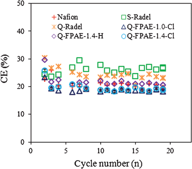 | ||
| Fig. 6 Coulombic efficiency (%) as a function of cycle number over MFC operation (19 d) (50 mM PBS, pH 7.0, 1000 Ω resistance, 0.5 g L−1 sodium acetate). | ||
3. Experimental
3.1 Polymer cathode catalyst binders
Bisphenol A and decafluorobiphenyl were purchased from Aldrich Chemical Co., USA and were purified by re-crystallization and vacuum sublimation, respectively, before use. NAFION® solution (NAFION® 117 solution, 5 wt% in a mixture of lower aliphatic alcohols and water) and all other chemicals (obtained from Aldrich) were reagent grade and used as received. The polymers Q-Radel and fluorinated polymers (Q-FPAE-1.0-Cl, Q-FPAE-1.4-Cl and Q-FPAE-1.4-H) were synthesized according to literature methods (details in ESI†). The numbers and suffix in the fluorinated polymers denoted the IEC and counter ion, e.g. Q-FPAE-IEC-counter ion. The ion exchange capacity and water uptake of the various polymers used in this study are shown in Table 3.3.2 Cathode construction
The 3 cm diameter cathodes (area = 7 cm2) were constructed by brush coating of a suspension containing commercial carbon-supported Pt catalyst (10% Pt on Vulcan XC-72, BASF Fuel Cells, Inc.) and polymer binders on wet-proofed carbon cloth (type B) on the MFC electrolyte side, with four PTFE diffusion layers on the air side as previously described.23 All polymers (Q-Radel, S-Radel, Q-FPAE-1.0-Cl, Q-FPAE-1.4-Cl and Q-FPAE-1.4-H) were dissolved in an alcohol and water solvent mixture at 5 wt% solid content (details in ESI†), and then applied to each cathode with 30 μL polymer solution and platinum (Pt) catalyst (0.5 mg cm−2 Pt for cathodes). This application procedure was designed to be similar to that employed for the NAFION® commercial polymer dispersions.153.3 Electrochemical measurements
LSV was performed at 1 mV s−1 on the cathodes at 30 °C. The reactor was filled with 13 mL of 200 mM phosphate buffer solution (PBS) (18.304 g L−1 Na2HPO4, 9.808 g L−1 NaH2PO4, 0.13 g L−1 KCl, 0.31 g L−1 NH4Cl, pH = 7) and equipped with a 1 cm2 platinum square counter electrode and an Ag/AgCl/KCl (3 M) reference electrode. Electrochemical impedance spectroscopy (EIS) was measured at 0.3 V (vs. normal hydrogen electrode (NHE)) over a frequency range of 105 to 0.006 Hz with a sinusoidal perturbation of 10 mV in the same reactor used for the LSV tests. The charge transfer resistance (Rct) was obtained by fitting the charge transfer impedance to an RC circuit. All electrochemical measurements were performed with new cathodes (before MFC measurements). EIS tests were also performed in the standard EIS cell described above after removal from cycled MFCs.3.4 MFC measurements
All MFC performance tests were conducted using single-chamber MFCs constructed as previously described,14 and the produced voltage (Ecell) and electrode potentials were measured at a fixed external circuit resistance (1000 Ω) using a multimeter and Ag/AgCl reference. After the reactors were operated on fresh substrate for about 2 h, the polarization and power density curves as a function of current density were conducted using the single-cycle methods29 after 20 min at each external resistance (1000–20 Ω). All the other parameters including current, current density, power density, and coulombic efficiency were calculated according to standard methods.2,314. Conclusions
MFCs with Q-FPAE-based cathodes showed similar MFC performance to NAFION®, which had a higher power density but lower coulombic efficiency than that of the non-fluorinated anionic and cationic polymers binders. Among the Q-FPAE binders, the power densities of Q-FPAE-1.4-H (1445 mW m−2) and Q-FPAE-1.4-Cl (1397 mW m−2) were higher than that of Q-FPAE-1.0 (1256 mW m−2) as a result of their higher IEC and water uptake. No significant difference was found between the HCO3− and Cl− counterions in the starting cathode preparation. Taken together, these results of electrochemical and MFC performance demonstrated that the fluorinated aromatic Q-FPAE-1.4 was an excellent replacement for NAFION® as the cathode binder.Aromatic fluorinated ionomers, such as the materials used here, can be synthesized under comparatively mild conditions using common polymer polymerization techniques, resulting in less costly materials than those with perfluorinated chemical structures. Thus, the fluorinated aromatic polymer binders examined here are potentially less expensive than NAFION® and also avoid the use of perfluorinated monomers and intermediates which are potentially harmful to human health.32
Acknowledgements
This research was supported by the Award KUS-I1-003-13 from the King Abdullah University of Science and Technology (KAUST). We thank Solvay Advanced Polymers for the donation of RADEL® polymer.References
- B. E. Logan, Microbial Fuel Cells, John Wiley & Sons, Inc., Hoboken, New Jersey, 2008 Search PubMed.
- B. E. Logan, B. Hamelers, R. Rozendal, U. Schrorder, J. Keller, S. Freguia, P. Aelterman, W. Verstraete and K. Rabaey, Microbial fuel cells: methodology and technology, Environ. Sci. Technol., 2006, 40, 5181–5192 CrossRef CAS.
- I. Shizas and D. M. Bagley, Journal of Energy Engineering, 2004, 130, 45 CrossRef.
- H. Liu, S. A. Cheng and B. E. Logan, Production of electricity from acetate or butyrate using a single chamber microbial fuel cell., Environ. Sci. Technol., 2005, 39, 658–662 CrossRef CAS.
- D. H. Park and J. G. Zeikus, Improved fuel cell and electrode designs for producing electricity from microbial degradation., Biotechnol. Bioeng., 2003, 81, 348–355 CrossRef CAS.
- U. Schrőder, J. Nieβen and F. Scholz, A generation of microbial fuel cells with current output boosted by more than one order of magnitude., Angew. Chem., Int. Ed., 2003, 42, 2880–2883 CrossRef.
- O. Lefebvre, W. K. Ooi, Z. Tang, M. Abdullah-Al-Mamun, D. H. C. Chua and H. Y. Ng, Optimization of a Pt-free cathode suitable for practical applications of microbial fuel cells, Bioresource Technology, 2009, 100, 4907–4910 CrossRef CAS.
- A. Rinaldi, B. Mecheri, V. Garavaglia, S. Licoccia, P. Di Nardo and E. Traversa, Engineering materials and biology to boost performance of microbial fuel cells: a critical review, Energy Environ. Sci., 2008, 1, 417–429 CAS.
- S. E. Oh, B. Min and B. E. Logan, Cathode performance as a factor in electricity generation in microbial fuel cells., Environ. Sci. Technol., 2004, 38, 4900–4904 CrossRef CAS.
- G. C. Gil, I. S. Chang, B. H. Kim, M. Kim, J. K. Jang, H. S. Park and H. J. Kim, Operational parameters affecting the performance of a mediator-less microbial fuel cell, Biosens. Bioelectron., 2003, 18, 327–338 CrossRef CAS.
- H. T. Pham, J. K. Jang, I. S. Chang and B. H. Kim, Improvement of cathode reaction of a mediatorless microbial fuel cell, J. Microbiol. Biotechnol., 2004, 14, 324–329 Search PubMed.
- S. A. Cheng, H. Liu and B. E. Logan, Power densities using different cathode catalysts (Pt and CoTMPP) and polymer binders (Nafion and PTFE) in single chamber microbial fuel cells, Environ. Sci. Technol., 2006, 40, 364–369 CrossRef CAS.
- F. Zhang, S. A. Cheng, D. Pant, G. Van Bogaert and B. E. Logan, Power generation using an activated carbon and metal mesh cathode in a microbial fuel cell, Electrochem. Commun., 2009, 11, 2177–2179 CrossRef CAS.
- F. Zhao, F. Harnisch, U. Schrőder, F. Scholz, P. Bogdanoff and I. Herrmann, Application of pyrolysed iron(II) phthalocyanine and CoTMPP based oxygen reduction catalysts as cathode materials in microbial fuel cells, Electrochem. Commun., 2005, 7, 1405–1410 CrossRef CAS.
- T. Saito, M. D. Merrill, V. J. Watson, B. E. Logan and M. A. Hickner, Investigation of ionic polymer cathode binders for microbial fuel cells, Electrochim. Acta, 2010, 55, 3398–3403 CrossRef CAS.
- T. Saito, T. H. Roberts, T. E. Long, B. E. Logan and M. A. Hickner, Neutral hydrophilic cathode catalyst binders for microbial fuel cells, Energy Environ. Sci., 2011, 4, 928–934 CAS.
- Y. H. Mo, P. Liang, X. Huang, H. Y. Wang and X. X. Cao, Enhancing the stability of power generation of single-chamber microbial fuel cells using an anion exchange membrane, J. Chem. Technol. Biotechnol., 2009, 84, 1767–1772 CrossRef CAS.
- X. Y. Zhang, S. A. Cheng, X. Huang and B. E. Logan, Improved performance of single-chamber microbial fuel cells through control of membrane deformation, Biosens. Bioelectron., 2010, 25, 1825–1828 CrossRef CAS.
- V. J. Watson, T. Saito, M. A. Hickner and B. E. Logan, Polymer coatings as separator layers for microbial fuel cell cathodes, J. Power Sources, 2011, 196, 3009–3014 CrossRef CAS.
- J. R. Kim, S. A. Cheng, S.-E. Oh and B. E. Logan, Power generation using different cation, anion, and ultrafiltration membranes in microbial fuel cells, Environ. Sci. Technol., 2007, 41, 1004–1009 CrossRef CAS.
- T. H. J. A. Sleutels, H. V. M. Hamelersa, R. A. Rozendal and C. J. N. Buisman, Ion transport resistance in microbial electrolysis cells with anion and cation exchange membranes, Int. J. Hydrogen Energy, 2009, 34, 3612–3620 CrossRef CAS.
- Z. S. Jia, D. F. Shen and W. L. Xu, Synthesis and antibacterial activities of quaternary ammonium salt of chitosan, Carbohydr. Res., 2001, 333, 1–6 CrossRef CAS.
- S. Cheng, H. Liu and B. E. Logan, Increased performance of single-chamber microbial fuel cells using an improved cathode structure, Electrochem. Commun., 2006, 8, 489–494 CrossRef CAS.
- F. Zhang, P. Deepak and B. E. Logan, Long-term performance of activated carbon air cathodes with different diffusion layer porosities in microbial fuel cells., Biosensors and Bioelectronics, 2011, 30, 49–55 CAS.
- A. Lasia, Nature of the two semi-circles observed on the complex plane plots on porous electrodes in the presence of a concentration gradient., J. Electroanal. Chem., 2001, 500, 30–35 CrossRef CAS.
- I. S. P. Savizi and M. J. Janik, Acetate and phosphate anion adsorption linear sweep voltammograms simulated using density functional theory., Electrochim. Acta, 2011, 56, 3996–4006 CrossRef CAS.
- M. G. Zhang, Q. T. Nguyen and Z. H. Ping, Hydrophilic modification of poly(vinylidene fluoride) microporous membrane, J. Membr. Sci., 2009, 327, 78–86 CrossRef CAS.
- M. Herzberg and M. Elimelech, Biofouling of reverse osmosis membranes: role of biofilm-enhanced osmotic pressure, J. Membr. Sci., 2007, 295, 11–20 CrossRef CAS.
- X. Y. Zhang, S. A. Cheng, X. Wang, X. Huang and B. E. Logan, Separator characteristics for increasing performance of microbial fuel cells, Environ. Sci. Technol., 2009, 43, 8456–8461 CrossRef CAS.
- A. P. Borole, D. Aaron, C. Y. Hamilton and C. Tsouris, Understanding long-term changes in microbial fuel cell performance using electrochemical impedance spectroscopy, Environ. Sci. Technol., 2010, 44, 2740–2744 CrossRef CAS.
- S. Cheng, H. Liu and B. E. Logan, Increased power generation in a continuous flow MFC with advective flow through the porous anode and reduced electrode spacing, Environ. Sci. Technol., 2006, 40, 2426–2432 CrossRef CAS.
- C. Heitner-Wirguin, Recent advances in perfluorinated ionomer membrane: structure, properties and applications, J. Membr. Sci., 1996, 120, 1–33 CrossRef CAS.
Footnote |
| † Electronic Supplementary Information (ESI) available. See DOI: 10.1039/c2ra20705b/ |
| This journal is © The Royal Society of Chemistry 2012 |

