Preparation and application of TEMPO-based di-radical organic electrode with ionic liquid-based polymer electrolyte
Jae-Kwang
Kim
*a,
Aleksandar
Matic
a,
Jou-Hyeon
Ahn
*b,
Per
Jacobsson
a and
Choong-Eui
Song
c
aDepartment of Applied Physics, Chalmers University of Technology, Göteborg, 412 96 Sweden. E-mail: jaekwang@chalmers.se; Fax: +46 31 772 2096; Tel: +46 31 772 3352
bDepartment of Chemical & Biological Engineering and Engineering Research Institute, Gyeongsang National University, 900, Gajwa-dong, Jinju 660-701, Korea. E-mail: jhahn@gnu.ac.kr; Fax: +82 55 772 1789; Tel: +82 55 772 1784
cInstitute of Basic Science and Department of Chemistry, Sungkyunkwan University, Suwon, Gyeonggi-do 440-746, Korea
First published on 25th September 2012
Abstract
In this study we report the synthesis and use of new organic materials, TEMPO di-radical [1,3-bis(4-(2,2,6,6,-tetramethyl-1-oxyl-4-piperidoxyl)butyl) imidazolium trifluorosulfonate]. Two cells were prepared with Li metal anode and the TEMPO di-radical based cathode with a microporous polymer electrolyte [1-butyl-3-methyl imidazolium bis(trifluoromethane sulfonyl) imide (BMImTFSI) in 0.5 M LiTFSI, and in 1 M LiPF6 in ethylene carbonate/dimethyl carbonate (EC/DMC)] hosted in electrospun poly(vinylidenefluoride-co-hexafluoropropylene) (PVdF-HFP) membrane. The nature of the solvent was not found to affect the basic redox reaction behavior of TEMPO. The anodic and cathodic peaks were obtained at almost the same position and with some difference in the separation of peaks. The presence of BMImTFSI significantly affects the electrochemical performance of the battery as the cell having this RTIL exhibited far better electrochemical performance with 100% utilization of the active material and reasonably good cycling performance up to 200 cycles. We believe that this composite cell will contribute to organic green rechargeable batteries, although the cell is not fully organic composite.
1. Introduction
Lithium batteries that are thin, flexible, light, safe and easily processable, are being researched for applications in several devices. These attributes are derived from organic/polymer radicals as active electrode materials, which have the additional benefit of their environmentally friendly nature. These features outweigh the advantages offered by the conventional cathode materials based on transition metal oxides. A stable organic/polymer radical based cathode material based on poly(2,2,6,6-tetramethylpiperidinyloxy-4-yl methacrylate) (PTMA) was first reported in 2002 by Nakahara et al.1 Thereafter, many reports on these promising high power secondary battery materials have appeared.2–17 The other positive electrode materials comprising of organic functional polymers such as polyacetylene,18 organic disulfides19 and conducting polymers20 exhibit poor performance mainly due to the low degree of doping achieved, slow redox reactions and unsteady cell voltages.PTMA has the nitroxide radical 2,2,6,6-tetramethyl-1-piperidinyloxy (TEMPO) as the repeating unit, which exhibits reversible oxidation-reduction behavior in aprotic solvents.21,22 TEMPO undergoes rapid redox reactions with an electron-transfer rate constant of the order of 10−1 cm s−1,23 which is several orders higher as compared to that of the organic redox couples of disulfides (∼10−8 cm s−1 at room temperature).24 The electrochemical behavior of TEMPO has been mostly studied in organic solvents.25 There are some reports wherein room temperature ionic liquids (RTIL) were reported as the solvent, and its CV behavior was compared with that observed in organic solvents. CV of TEMPO in [BMIm][PF6] shows E1/2 = 0.24 V that corresponds to the one-electron reversible TEMPO/TEMPO+ redox couple. It was revealed that the nature of electrochemical process of TEMPO is not significantly altered in RTILs, though the effect of the viscous nature of RTIL results in low diffusion coefficient of the redox couple and the resulting low anodic and cathodic peak currents.26 The electrochemical behavior of TEMPO in [BMIm][PF6] is quite similar to that in CH3CN, in terms of anodic to cathodic current ratio and peak separation. The rates of apparent heterogeneous and homogeneous electron-transfer reactions are lower in the IL as compared to CH3CN due to the difference in viscosities, and so is the redox currents largely suppressed compared to that in CH3CN.27 The introduction of cyano or acetamido groups have profound effect on the properties of TEMPO including increase in the redox potential as predicted by Hammett substituent values for the electron withdrawing groups, as the redox potential of acetamido-TEMPO was shifted by +300 mV relative to TEMPO, while that of the cyano-TEMPO was shifted only by +150 mV.28
In view of the above and in continuation of our earlier work on PTMA based cathode materials, in this article we report synthesis and use of TEMPO di-radical [1,3-bis(4-(2,2,6,6,-tetramethyl-1-oxyl-4-piperidoxyl)butyl) imidazolium trifluorosulfonate] as the cathode material. Two polymer electrolytes were prepared with 1-butyl-3-methyl imidazolium bis(trifluoromethane sulfonyl) imide (BMImTFSI) in 0.5 M LiTFSI and also in ethylene carbonate/dimethyl carbonate (EC/DMC) in 1 M LiPF6 and hosted in the PVdF-HFP electrospun membranes. The RTILs have high ionic conductivity at room temperature and a wide electrochemical window exhibiting good electrochemical stability in the range of 4.0–5.7 V.29 The addition of an RTIL to the lithium batteries improves their performance at moderate temperatures and ensures safety owing to the intrinsic properties of ILs.30–32 Moreover, the use of RTIL prevents the dissolution of organic electrode material, which induce a short circuit of the battery.33 On the other hand, the use of organic carbonates as solvents in lithium batteries is a safety hazard.34 Thus, apart from getting insight into the effect of the presence of RTIL on the electrochemical behavior and performance of the di-radical cathode material, it is expected that the presence of RTIL will add to the development of safe, green, rechargeable batteries.
2. Experimental
The TEMPO-based di-radicals are presented in Scheme 1. 4-Hydroxy-TEMPO was reacted with 1,4-dibromobutane in acetone and in the presence of NaH at 25 °C for 3 h. The bromide adduct thus obtained was refluxed with imidazole in 2![[thin space (1/6-em)]](https://www.rsc.org/images/entities/char_2009.gif) :
:![[thin space (1/6-em)]](https://www.rsc.org/images/entities/char_2009.gif) 1 molar ratio for 48 h in acetone in the presence of K2CO3. Subsequently, anion exchange was carried for 72 h at room temperature with KCF3SO3 in acetonitrile to obtain 1,3-bis(4-(2,2,6,6,-tetramethyl-1-oxyl-4-piperidoxyl)butyl)imidazolium trifluorosulfonate.
1 molar ratio for 48 h in acetone in the presence of K2CO3. Subsequently, anion exchange was carried for 72 h at room temperature with KCF3SO3 in acetonitrile to obtain 1,3-bis(4-(2,2,6,6,-tetramethyl-1-oxyl-4-piperidoxyl)butyl)imidazolium trifluorosulfonate.
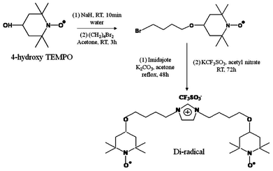 | ||
| Scheme 1 Synthesis of 1,3-bis(4-(2,2,6,6,-tetramethyl-1-oxyl-4-piperidoxyl)butyl)imidazolium trifluorosulfonate. | ||
The porous membrane of P(VdF-HFP) polymer was prepared by electrospinning process under conditions optimized in our laboratory.11 A 17 wt% solution of P(VdF-HFP) (Kynar Flex 2801) in a mixed solvent (7![[thin space (1/6-em)]](https://www.rsc.org/images/entities/char_2009.gif) :
:![[thin space (1/6-em)]](https://www.rsc.org/images/entities/char_2009.gif) 3 by wt. ratio) of acetone and N,N,dimethylacetamide (HPLC grade, Aldrich) was electrospun in a common set up at room temperature. Polymer electrolyte (PE) was prepared by soaking the membrane for 10 min with a solution of 1 M LiPF6 in ethylene carbonate (EC)/dimethyl carbonate (DMC) (1
3 by wt. ratio) of acetone and N,N,dimethylacetamide (HPLC grade, Aldrich) was electrospun in a common set up at room temperature. Polymer electrolyte (PE) was prepared by soaking the membrane for 10 min with a solution of 1 M LiPF6 in ethylene carbonate (EC)/dimethyl carbonate (DMC) (1![[thin space (1/6-em)]](https://www.rsc.org/images/entities/char_2009.gif) :
:![[thin space (1/6-em)]](https://www.rsc.org/images/entities/char_2009.gif) 1 by vol.) and 1-butyl-3-methyl imidazolium bis(trifluoromethane sulfonyl) imide (BMImTFSI) in 0.5 M LiTFSI under argon atmosphere in a glove box (H2O < 10 ppm). The lithium salt and organic solvents were supplied by Aldrich.
1 by vol.) and 1-butyl-3-methyl imidazolium bis(trifluoromethane sulfonyl) imide (BMImTFSI) in 0.5 M LiTFSI under argon atmosphere in a glove box (H2O < 10 ppm). The lithium salt and organic solvents were supplied by Aldrich.
The di-radical was characterized by 1H NMR (300 MHz, CDCl3) and 13C NMR (75 MHz, CDCl3) spectroscopy by recording spectra on Varian 300 spectrometer using TMS as internal standard. Scanning electron microscopy was carried on SEM: JEOL JSM 5600. The cathode was fabricated by blending the di-radical based active material, conductive carbon (Super-P: Aldrich) and poly(vinylidene fluoride) (PVdF: Aldrich) binder in a ratio of 40![[thin space (1/6-em)]](https://www.rsc.org/images/entities/char_2009.gif) :
:![[thin space (1/6-em)]](https://www.rsc.org/images/entities/char_2009.gif) 50
50![[thin space (1/6-em)]](https://www.rsc.org/images/entities/char_2009.gif) :
:![[thin space (1/6-em)]](https://www.rsc.org/images/entities/char_2009.gif) 10 by weight. The components were mixed thoroughly in NMP at room temperature by ball milling for 30 min and the viscous slurry so obtained was cast on aluminum foil and dried at 60 °C under a vacuum for 12 h. The thin film so prepared (∼20 μm thick) was cut into circular discs with an area of 0.95 cm2 to evaluate its use as a cathode material. Two-electrode electrochemical coin cells were assembled with a lithium metal (300 μm thickness, Cyprus Foote Mineral Co.) anode, radical cathode and 40 μL of 1 M LiPF6 in ethylene carbonate (EC)/dimethyl carbonate (DMC) (1
10 by weight. The components were mixed thoroughly in NMP at room temperature by ball milling for 30 min and the viscous slurry so obtained was cast on aluminum foil and dried at 60 °C under a vacuum for 12 h. The thin film so prepared (∼20 μm thick) was cut into circular discs with an area of 0.95 cm2 to evaluate its use as a cathode material. Two-electrode electrochemical coin cells were assembled with a lithium metal (300 μm thickness, Cyprus Foote Mineral Co.) anode, radical cathode and 40 μL of 1 M LiPF6 in ethylene carbonate (EC)/dimethyl carbonate (DMC) (1![[thin space (1/6-em)]](https://www.rsc.org/images/entities/char_2009.gif) :
:![[thin space (1/6-em)]](https://www.rsc.org/images/entities/char_2009.gif) 1 v/v) electrolyte, and the another in BMImTFSI in 0.5 M LiTFSI in P(VdF-HFP) electrospun membranes. The cells were designated as CellEC/DMC and CellBMImTFSI to highlight the nature of the solvent in each case. The cell was assembled under an argon atmosphere in a glove box with a level of H2O < 10 ppm. The charge-discharge and cycling properties of the batteries were evaluated between 2.75 and 4.0 V at different current densities using an automatic galvanostatic charge-discharge unit, WBCS-3000 battery cycler (WonA Tech. Co.), at 25 °C. Cyclic voltammetry (CV) measurements of the cell were conducted at a scan rate of 0.5 mV s−1 between 2.5 and 4.4 V.
1 v/v) electrolyte, and the another in BMImTFSI in 0.5 M LiTFSI in P(VdF-HFP) electrospun membranes. The cells were designated as CellEC/DMC and CellBMImTFSI to highlight the nature of the solvent in each case. The cell was assembled under an argon atmosphere in a glove box with a level of H2O < 10 ppm. The charge-discharge and cycling properties of the batteries were evaluated between 2.75 and 4.0 V at different current densities using an automatic galvanostatic charge-discharge unit, WBCS-3000 battery cycler (WonA Tech. Co.), at 25 °C. Cyclic voltammetry (CV) measurements of the cell were conducted at a scan rate of 0.5 mV s−1 between 2.5 and 4.4 V.
3. Results and discussion
At room temperature, the IL-supported di-radical is orange-red colored material, purity >95% (TLC), mp ∼220 °C. The chemical structure of the synthesized IL-supported TEMPO di-radical was confirmed by spectral analysis. The signals in the 1H NMR spectrum [δ 1.21 (s, 12H), 1.31 (s, 12H), 1.40–1.62 (m, 8H), 1.78–2.04 (m, 8H), 3.43 (t, J = 6.3 Hz, 2H), 3.49 (t, J = 5.7 Hz, 2H), 3.54–3.65 (m, 2H), 4.22 (t, J = 7.5 Hz, 4H), 7.36 (s, 2H), 8.88 (s, 1H)] corresponds to the number of proton and their expected coupling with the neighboring protons (Fig. 1a). The information contained in the 1H spectrum is supported by the signals observed in the 13C NMR spectrum (δ 135.5, 122.6, 71.0, 67.4, 59.5, 50.1, 44.9, 32.4, 27.8, 26.6, 20.8, 320.1 C–F) (Fig. 1b).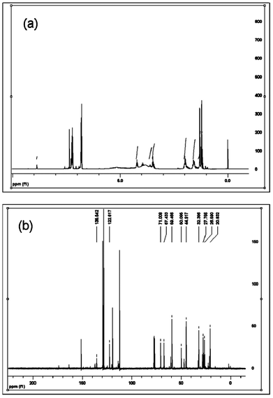 | ||
| Fig. 1 (a) 1H NMR of 1,3-bis(4-(2,2,6,6,-tetramethyl-1-oxyl-4-piperidoxyl)butyl)imidazolium trifluorosulfonate and (b) 13C NMR of 1,3-bis(4-(2,2,6,6,-tetramethyl-1-oxyl-4-piperidoxyl)butyl)imidazolium trifluorosulfonate. | ||
An organic radical battery (ORB) operating at room temperature with lithium metal anode and di-radical [1,3-bis(4-(2,2,6,6,-tetramethyl-1-oxyl-4-piperidoxyl)butyl) imidazolium trifluorosulfonate] cathode with a microporous gel polymer electrolyte based on electropsun poly(vinylidenefluoride-co-hexafluoropropylene) (PVdF-HFP) membrane has been demonstrated. The gel polymer electrolyte with pore structure, high electrolyte uptake and high ionic conductivity is found to be suitable for use in TEMPO-based ORBs. Common features are that the energy-providing processes take place at the phase boundary of the electrode/gel polymer electrolyte interface and that electron and ion transport are separated. Scheme 1 shows the basic operation mechanisms of the di-radical battery system. The di-radical batteries consist of two electrodes in contact with a gel polymer electrolyte. The requirements on electron and ion conduction in electrodes and the gel polymer electrolyte are given in Scheme 2. In radical batteries, electrical energy is generated by conversion of chemical energy via redox reactions at the anode take place at lower electrode potentials than at the cathode, the terms negative and positive electrode are used. Scheme 2 depicts the anodic oxidation (p-type doping) reaction of the nitroxide radical in IL-supported, TEMPO-based di-radical that is responsible for its electrochemical activity as a cathode-active material in lithium batteries. To maintain a proper balance of charges at the di-radical cathode during the charge-discharge process, the anion in the electrolyte takes part in the redox reaction.
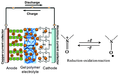 | ||
| Scheme 2 Presentation of the di-radical cell and redox reaction of the nitroxide radical. | ||
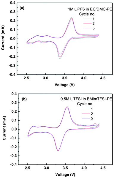
The CV curves of the lithium batteries prepared with the di-radical cathode are shown in Fig. 2. There is a single redox couple with an active voltage in the same range. CellEC/DMC shows redox couple peaks at 3.7 V and 3.35 V versus Li/Li+ while the cathodic peak is lower (3.3 V) in the case of CellBMImTFSI. The redox current for CellBMImTFSI (0.272, 0.257 mA) is more than about 0.02 mA that of CellEC/DMC (0.252, 0.231 mA). The potential separation between the anodic and cathodic peaks (ΔV) is 0.35 V and 0.25 V for CellEC/DMC and CellBMImTFSI respectively. This narrow peak separation on both cells results from the fast redox reaction kinetics of the nitroxyl radical. The smaller redox current and higher peak separation in the case of CellEC/DMC is a manifestation of the higher interface resistance of the 1 M LiPF6 in EC/DMC-based gel polymer electrolyte. The symmetric oxidation and reduction peaks with the comparable area indicate a high coulombic efficiency for the charge-discharge process. This is an indication of the low ohmic resistance (polarization) of the electrode, which evidently results from the homogeneous cathode structure with sufficient conductivity making efficient charge transfer. After 5 cycles, there were no significant shifts in the redox peaks, as both the cells exhibited good redox reaction stability and it was more so in the case of CellBMImTFSI. There is no significant effect of the presence of the viscous RTIL on the nature of electrochemical behavior of the TEMPO di-radical, but the diffusion coefficient of the redox couple and the cell stability are affected as can be made out from the differences in the redox peaks separation and redox behavior after 5 cycles.
Fig. 3a shows the charge and discharge behavior of CellEC/DMC at 1 C-rate. The theoretical capacity of the di-radical is 80.0 mAh g−1 as it has molecular weight of 670 and two electrons available for the redox reaction. The anodic and cathodic peaks appear at 3.7 and 3.35 V, respectively, which is in agreement with the observations made earlier based on CV studies. The charge and discharge capacity increased with the increase of the cycle numbers with the respective maximum values of 68 and 62.4 mAh g−1 obtained after 5 cycles. The electrochemical behavior of CellBMImTFSI is different from the other cell in two aspects (Fig. 3b). One, there is no variation in the charge or discharge capacities, thus exhibiting stability of the cathode material that can be ascribed to the viscous nature of BMImTFSI. Two, relatively far better performance has been observed in this case as the respective charge and discharge capacities of 80 of 80 mAh g−1 were obtained. It is thus reasonable to suggest that BMImTFSI contributes to the electrochemical processes. At 10 C-rate, the performance of the two cells was still better. The charge and discharge capacities for different cycles changed from 80, 80 and 79.9 mAh g−1, and 74.13, 73.96 and 72.17 mAh g−1 for the CellEC/DMC (Fig. 3c). These values are higher at 80, 80, 79.87 mAh g−1, and 80, 79.24 and 77.62 mAh g−1, respectively, in the case of CellBMImTFSI (Fig. 3d). The maximum utilization of the active material at the initial stage is higher at 100% in the case of CellBMImTFSI as compared to 92.66% for the other cell. It should be noted that a dissolution or undesired reaction of active material has been reported to be even more evident at 1 C.
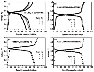 | ||
| Fig. 3 Charge-discharge curve of (a) CellEC/DMC, and (b) CellBMImTFSI at 1 C-rate. Charge-discharge curve of (c) CellEC/DMC and (d) CellBMmITFSI at 10 C-rate. | ||
The effect of the nature of the solvent on the electrochemical performance of the cells is more pronounced when the cycling performance was studied at 1 C-rate. The charge and discharge capacities changed from 58.03 to 39.25 mAh g−1 and 51.61 to 37.1 mAh g−1 after 110 cycles (Fig. 4a). It is interesting to note that the capacities increase with the increase of cycling till 20 cycles, and thereafter decreased in a gradual manner. Such behavior is ascribed to the initial solvent-polymer interactions that results in generation of amorphous regions in the polymer, hence initial enhancement of the capacities. However, greater swelling of fiber slows down the redox process due to the chain entanglements and reduced availability of the solvent for the electrolyte. Such behavior was not observed with CellBMImTFSI, which exhibited high capacities and low capacity loss, thus showing superior cycling stability. In this cell the charge and discharge capacities changed from 80 and 80 mAh g−1 to 54.7 and 54.9 mAh g−1, respectively, after 110 cycles (Fig. 4b). These observations were further reinforced when the cycling was studied at 10 C-rate and up to 200 cycles. The charge and discharge capacities changed from 80 and 74.12 mAh g−1 to 42.4 and 40.1 mAh g−1 after 200 cycles in CellEC/DMC, while the respective values were 80 and 80 mAh g−1 to 54.2 and 53.7 mAhg−1, respectively, for the CellBMImTFSI (Fig. 4c, d). The capacity fade was faster in the earlier 40 cycles in CellEC/DMC (Fig. 4c). In the CellBMImTFSI, charge and discharge capacities decrease little by little during each cycle (Fig. 4d). In both the cells, the capacity loss was lower after 80 cycles. The capacity fade is lower and more cycle stability was observed in the latter case and the stability factor can be attributed to the viscous nature of the RTIL. The charge capacities are in agreement with the respective discharge capacities in CellBMImTFSI, indicating the high coulombic efficiency of the redox process in this battery. The decrease in the discharge capacity during the initial cycles is observed probably due to the initial interactions of the electrolyte at the lithium electrode, which would form an interface restricting the free movement of the ions. As the cycling advances, the performance of the ORB also stabilizes, indicating the formation of stable electrode/electrolyte interface in the cells.
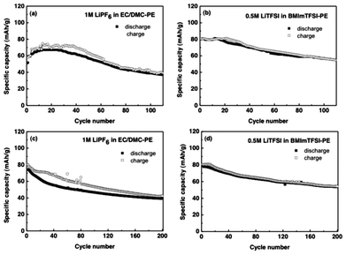 | ||
| Fig. 4 Cycling performance of (a) CellEC/DMC, and (b) CellBMImTFSI during 110 cycles at 1 C-rate. Cycling performance of (c) CellEC/DMC, and (d) CellBMImTFSI at 10 C-rate after 200 cycles. | ||
The effect of solvent on the surface morphology of cathode after 110 cycles is evident from Fig. 5. After 110 cycles at 1 C rate, the differences in the surface morphology of the active cathode material in these cells is discrete. After 110 cycles, the surface morphology of CellEC/DMC underwent major changes as compared to what it was before the charge-discharge process (Fig. 5a, b). The changes in the shape from spherical to rectangular and increase in size of the cathode material particles to ∼300 nm is also obvious from Fig. 5c, d. On the other hand, the surface morphology of the other battery remained the same as was before the charge-discharge process (Fig. 5a, b and e, f). The changes in the surface morphology of the cathode martial in these two batteries are self-explanatory to support the differences in the electrochemical performance and cycling stability of the two batteries. The active material remained uniformly distributed within the cathode matrix of CellBMImTFSI as is evident from the Fig. 5e, f. The active cathode material of CellBMImTFSI has spherical particles with a smaller size of ∼180 nm which are held together by the ionic liquid (Fig. 5e, f). The comparison of the changes in the surface morphologies from the SEM of the electrospun P(VdF-HFP) membrane is also important to reveal the role of the nature of solvent on the electrochemical performance of these batteries.
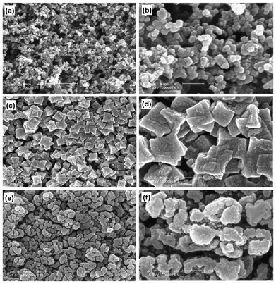 | ||
Fig. 5 SEM images of electrode before charge-discharge process (a, b), CellEC/DMC (c, d) and CellBMImTFSI (e, f) after 110 cycles at 1 C (×30![[thin space (1/6-em)]](https://www.rsc.org/images/entities/char_2009.gif) 000, ×100 000, ×100![[thin space (1/6-em)]](https://www.rsc.org/images/entities/char_2009.gif) 000). 000). | ||
As compared to the as-prepared membrane (Fig. 6a), discernible changes were observed after cycling in the structure of the membrane that hosted electrolyte in the organic carbonates. These include swelling, increase in the diameter and chain entanglements (Fig. 6b). The surface morphology of the membrane hosting BMImTFSI did not show any such changes (Fig. 6c). Thus, SEM images provide important evidence about the changes that the cathode material or the membrane underwent after cycling. From SEM images, we can speculate that the di-radical cathode also induces the dissolution into electrolyte with EC/DMC.33 The homogeneity of the cathode structure and its retention during the cycling in CellBMImTFSI supports its power-rate capability. The nature of the active material contributes to the uniform composition of the cathode in more viscous BMImTFSI, which supports its high stability and rate-capability.
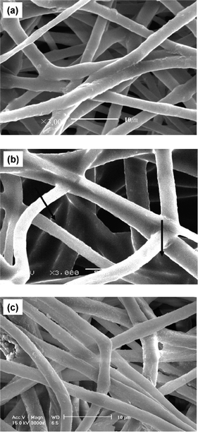 | ||
| Fig. 6 of (a) As-prepared PVdF-HFP membrane, (b) after 110 cycles in CellEC/DMC and (c) after 110 cycles in CellBMImTFSI. | ||
Conclusions
The evaluation of the electrochemical properties of IL-supported TEMPO-derived organic di-radicals as cathode materials for lithium secondary batteries was investigated. Two polymer electrolytes were prepared in electrospun P(VdF-HFP) microfibrous membranes in organic carbonates or ionic liquid. The nature of the solvent does not affect the basic nature of the redox couple observed for TEMPO, but the presence of BMImTFSI makes a difference in the improvement of the electrochemical performance of the battery. The cell containing BMImTFSI exhibited 100% material utilization and good cycleability up to 200 cycles. The SEM images support the stability of PE in the presence of BMImTFSI. This study revealed that the TEMPO diradical is a good candidate as an active cathode material for the lithium secondary batteries as it exhibited high discharge capacities with high cycleability. The TEMPO-derived di-radical is also attractive as an active cathode material due to high flat voltage and high rate capability. These novel, IL-supported radicals exhibit electrochemical characteristics similar to those of PTMA with the advantage of easier processing.Acknowledgements
The present work was supported by STINT and NRF in a joint Korea-Sweden program and the Swedish Energy Agency, and the Chalmers Area of Advance-Energy.References
- K. Nakahara, S. Iwasa, M. Satoh, Y. Morioka, J. Iriyama, M. Suguro and E. Hasegawa, Chem. Phys. Lett., 2002, 359, 351 CrossRef CAS.
- K. Nakahara, S. Iwasa, J. Iriyama, Y. Morioka, M. Suguro, M. Satoh and E. J. Cairns, Electrochim. Acta, 2006, 52, 921 CrossRef CAS.
- K. Nakahara, J. Iriyama, S. Iwasa, M. Suguro, M. Satoh and E. J. Cairns, J. Power Sources, 2007, 163, 1110 CrossRef CAS.
- K. Nakahara, J. Iriyama, S. Iwasa, M. Suguro, M. Satoh and E. J. Cairns, J. Power Sources, 2007, 165, 870 CrossRef CAS.
- K. Nakahara, J. Iriyama, S. Iwasa, M. Suguro, M. Satoh and E. J. Cairns, J. Power Sources, 2007, 165, 398 CrossRef CAS.
- H. Nishide and T. Suga, Electrochem. Soc. Interface, 2005, 14, 32 CAS.
- H. Nishide, S. Iwasa, Y.-J. Pu, T. Suga, K. Nakahara and M. Satoh, Electrochim. Acta, 2004, 50, 827 CrossRef CAS.
- Y. Yonekuta, K. Susuki, K. Oyaizu, K. Honda and H. Nishide, J. Am. Chem. Soc., 2007, 129, 14128 CrossRef CAS.
- T. Suga, H. Konishi and H. Nishide, Chem. Commun., 2007, 17, 1730 RSC.
- H. Li, Y. Zou and Y. Xia, Electrochim. Acta, 2007, 52, 2153 CrossRef CAS.
- J.-K. Kim, G. Cheruvally, J.-W. Choi, J.-H. Ahn, D.-S. Choi and C.-E. Song, J. Electrochem. Soc., 2007, 154, A839 CrossRef CAS.
- J.-K. Kim, G. Cheruvally, J.-W. Choi, J.-H. Ahn, S.-H. Lee, D.-S. Choi and C.-E. Song, Solid State Ionics, 2007, 178, 1546 CrossRef CAS.
- (a) S.-H. Lee, J.-K. Kim, G. Cheruvally, J.-W. Choi, J.-H. Ahn, G.-S. Chauhan and C.-E. Song, J. Power Sources, 2008, 184, 50 Search PubMed; (b) W. Qian, E. Jin, W. Bao and Y. Zhang, Tetrahedron, 2006, 62, 556 CrossRef CAS.
- J.-K. Kim, G. Cheruvally, J.-H. Ahn, Y.-G. Seo, D.-S. Choi, S.-H. Lee and C.-E. Song, J. Ind. Eng. Chem., 2008, 14, 371 CrossRef CAS.
- K. Oyaizu and H. Nishide, Adv. Mater., 2009, 21, 2339 CrossRef CAS.
- (a) J.-K. Kim, J.-H. Ahn, G. Cheruvally, G. S. Chauhan, J.-W. Choi, D.-S. Kim, H.-J. Ahn, S.-H. Lee and C.-E. Song, Met. Mater. Int., 2009, 15, 77 CrossRef CAS; (b) M.-K. Hung, Y.-H. Wang, C.-H. Lin, H.-C. Lin and J.-T. Lee, J. Mater. Chem., 2012, 22, 1570 RSC.
- (a) S. Yoshihara, H. Katsuta, H. Isozumi, M. Kasai, K. Oyaizu and H. Nishide, J. Power Sources, 2011, 196, 7806 CrossRef CAS; (b) W. Guo, Y.-X. Yin, S. Xin, Y.-G. Guo and L.-J. Wan, Energy Environ. Sci., 2012, 5, 5221 RSC.
- D. MacInnes, Jr., M. A. Druy, P. J. Nigrey, D. P. Nairns, A. G. MacDiarmid and A. J. Heeger, J. Chem. Soc., Chem. Commun., 1981, 7, 317 RSC.
- S. J. Visco, C. C. Mailhe, L. C. DeJonghe and M. B. Armand, J. Electrochem. Soc., 1989, 136, 661 CrossRef CAS.
- L. Nyholm, G. Nyström, A. Mihranyan and M. Strømme, Adv. Mater., 2011, 23, 3751 CAS.
- F. MacCorquodale, J. A. Crayston, J. C. Walton and D. J. Worsfold, Tetrahedron Lett., 1990, 31, 771 CrossRef CAS.
- T. Katsumata, M. Satoh, J. Wada, M. Shiotsuki, F. Sanda and T. Masuda, Macromol. Rapid Commun., 2006, 27, 1206 CrossRef CAS.
- T. Suga, Y. J. Pu, K. Oyaizu and H. Nishide, Bull. Chem. Soc. Jpn., 2004, 77, 2203 CrossRef CAS.
- M. Liu, S. J. Visco and L. C. D. Jonghe, J. Electrochem. Soc., 1990, 137, 750 CrossRef CAS.
- P. Krzyczmonik and H. Scholl, J. Electroanal. Chem., 1992, 335, 233 CrossRef CAS.
- S. Kishioka, T. Ohsaka and K. Tokuda, Electrochim. Acta, 2003, 48, 1589 CrossRef CAS.
- A. C. Herath and J. Y. Becker, Electrochim. Acta, 2008, 53, 4324 CrossRef CAS.
- M. Taggougui, B. Carŕe, P. Willmann and D. Lemordant, J. Power Sources, 2007, 174, 643 CrossRef CAS.
- J.-S. Oh, Y. Kang and D.-W. Kim, Electrochim. Acta, 2006, 52, 1567 CrossRef CAS.
- J.-H. Shin, W. A. Henderson, S. Scaccia, P. P. Prosini and S. Passerini, J. Power Sources, 2006, 156, 560 CrossRef CAS.
- M. Armand, F. Endres, D. R. MacFarlane, H. Ohno and B. Scrosati, Nat. Mater., 2009, 8, 621 CrossRef CAS.
- B. Scrosati, J. Hassoun and Y.-K. Sun, Energy Environ. Sci., 2011, 4, 3287 CAS.
- J.-K. Kim, P. Jacobsson and A. Matic, 12th International Symposium on Polymer Electrolytes, Italy, Padova, Aug. 29.–Sep. 3. 2010 Abstract p242 Search PubMed.
- P. G. Balakrishnan, R. Ramesh and T. Prem Kumar, J. Power Sources, 2006, 155, 401 CrossRef CAS.
| This journal is © The Royal Society of Chemistry 2012 |

