Encapsulation of highly toxic organic compounds: Novelly functionalized nanoparticles for the safe storage of pollutants and their by-products
Petrişor Zamora
Iordache†
*,
Rodica Mihaela
Lungu†
* and
Ioan
Safta
*
Scientific Research Center for CBRN Defense and Ecology, Oltenitei 225, Bucharest, Romania. E-mail: ioan.safta@nbce.ro; Fax: +40 213 322 115; Tel: +40 213 321 199iordachezamora1978@gmail.com; Tel: +40 722 126 129rodi_lm@yahoo.com; Tel: +40 745 173 967
First published on 16th July 2012
Abstract
This work reports the fabrication of a novel functionalized nanocomposite material capable of reticulation, degradation and the efficient encapsulation of very toxic organic compounds and their degradation by-products. The degradation and encapsulation efficiency was investigated by testing our material on (RS)-O-isopropyl methylphosphonofluoridate (GB), 2,2′-dichlorodiethyl sulfide (HD) and dimethyl methylphosphonate (DMMP). The morphological and morphochemical structure was investigated by means of TEM, SEM and EDX spectrometry. Likewise, the functional structure of the material and the degradation and encapsulation efficiency of toxic compounds and their degradation by-products were elucidated by means of IR spectrometry and gas chromatography coupled with mass spectrometry (GC-MS). It has been found that our fabricated nanocomposite shows a highly structural and functional stability, without counting residual traces of toxic compounds, degradation by-products or molecular fragments coming from degradation samples or from the internal structure of nanocomposite framework. Moreover, experimental evidence proves that our nanocomposite is able to degrade and encapsulate all toxic compounds and all their degradation by-products in less than 16, 5.35, 1 min (in the case of HD, GB and DMMP, respectively), both by catalytic and reticulation processes. We also formulated mechanisms for the degradation and encapsulation of tested toxic compounds and their intermediary by-products in the presence of functionalized substrate. We found that chemically active molecular clusters and Brønsted–Lewis sites coming from the composite framework catalyze the degradation processes. Moreover, we found that grafted functionalities, uncoordinated and unbound metal atoms and metal ion sites play a significant role in reticulation and encapsulation processes.
Introduction
Research in wastewater de-pollution and solid waste management usually encounters three main challenging problems: (1) the huge quantities of water to be processed, (2) the large varieties of contaminants and impurities, and (3) the conversion of solid residuals coming from specific treatments into chemically and biologically inert materials for their safe disposal. Additionally, the recycling of useful compounds is a preferential design target for most research, but in many cases the safe disposal of inactivated residuals prevails. In spite of the many advances in wastewater treatment, the problem of organic pollutant removal still depends on elaborate technologies developed under the tertiary wastewater treatment concept. Thus, oxidative technologies are expensive and degradation products are still polluting the water.1,2 Flocculation and coagulation, as well as ionic exchange technologies are limited in their efficiency of removing organic compounds.3–5 Chlorination is often used in the treatment of organic polluted waters, but its drawback is well-known—a large number of pollutants are converted into other compounds with the same toxicity. Microbiological technologies and photocatalytic technologies are very selective and totally inappropriate for a broad spectrum of organic pollutants in the treated wastewaters.6–8 Membrane materials, nanostructured materials and functionalized hybrid nanomaterials, as well as adsorbent functionalized composite materials seem to be the best solutions for the treatment of wastewaters which are highly contaminated with a large number of organic compounds coming from different classes.9–11 Only the prices of these materials are restrictive in their application on a large scale.This work presents the results of a series of research wherein the main goal was the modelling of properties and the adequate preparation of materials capable of reticulating, degrading and encapsulating certain classes of organic pollutants in a single step. Taking these approaches into account, we model different types of nanoparticle-based functionalized mixtures in order to fulfil the imposed operational restraints. In addition, our strategy was justified by theoretical and experimental evidence showing that functionalized nanoparticles (FC) have remarkable features, due to the variable grafting methods of chemical functionalities and the selection of optimal properties in mixing the functionalized oxides. The modelling processes start from the main assumption that different types of functional groups grafted in the framework of the host composite may reticulate various types and classes of organic compounds. Unpublished experimental evidence shows that in most cases of investigated functionalized materials, the reticulation process ends with the pollutant molecule breaking up and the release of degradation by-products. Moreover, we observed that secondary by-products are quickly captured by the nearest neighbouring functionalized surfaces. As a result of the physical and chemical interactions between the reticulated pollutants and the framework of host nanocomposites, the pollutants and their degradation by-products seem to be trapped inside the material structure, so that they could not be released. The pollutant encapsulation is a direct consequence of the degradation processes, which have the appearance of intermediary toxic by-products as a result. In the final stage of the degradation processes, the by-products can be partially or totally trapped in the depth of the FC framework by stable reticulation bonds, so that they could not be released. Following these approaches, selective materials might be developed and used for the removal of a singular class of harmful organic compounds or intermediary degradation by-products. Moreover, such materials fit the behaviour of smart materials very well, offering promising solutions for the most urgent needs in wastewater de-pollution, such as: the removal of toxic and very toxic organic compounds after wastewater preliminary treatments; the development of water treatment technologies, involving both ionic and non-ionic harmful compounds; the development of novel membranes, filtration and ultrafiltration materials; the decontamination of ground and surface waters; the development of environmentally friendly biodegradable materials.
Experimental and characterisation procedures
Fabrication of nanocomposite structural elements
The functionalized nanoparticles we have fabricated have three types of distinct functionalized Fe3O4 nanoparticles incorporated in their structure. The fabrication strategy is presented in Fig. 1 and starts from the assumption that metal oxide nanoparticles can be easily functionalized and can easily host various forms of functional groups. Even in an un-functionalized state, as chemically active “open surface nanostructures”, metal oxide-based surfaces act as a dynamic host–guest linker for their nearest functionalities.47 Furthermore, the morphological structure of this type of functionalized nanocomposite materials can present a high degree of two- and three-dimensional compactness, which can favour the encapsulation of very toxic organic compounds and of their degradation by-products. Secondly, Fe3O4 nanoparticles can be easily obtained and their correspondent Fe3O4-based nanocomposites can be used in special applications of the controlled magnetic separation type. Fig. 1 shows the main functional groups which we expect to be grafted on carrier nanoparticles coming from the framework of our fabricated nanocomposites.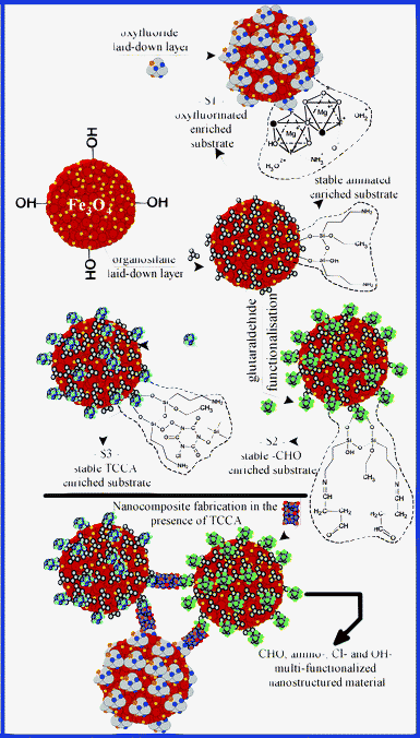 | ||
| Fig. 1 Fabrication diagram and the resulting main functional structure for the structural elements of the fabricated nanocomposite. | ||
In the first stage of the fabrication process, the Fe3O4 nanoparticles were obtained by co-precipitation. Magnesium oxyfluoride (Mg(OH)n−xFx) was obtained by sol–gel route through the reaction of a solution of MgCl2·6H2O (0.05 mol dm−3) with a solution of NaF (0.1 mol dm−3), at a temperature of 80 °C. The obtained gel was mixed with 200 mL of a Fe3O4 nanoparticle suspension (∼ 4%), in the presence of 30 ml NH4OH (35%). Finally, the first structural element (S1) was obtained as a Fe3O4 magnesium-based oxyfluoride coated nanoparticle. Further, 300 ml of Fe3O4 suspension were coated with an aminosilane layer, using a built-up mixture made up of 450 mL ethanol, 8 mL 3-aminopropyltriethoxysilane and 105 mL NH4OH (28%). After 60 min, the coated nanoparticles were washed with demineralized water and separated by centrifugation. A second component was achieved by mixing 200 mL of silane coated nanoparticle suspension with 6 mL glutaraldehyde (GL, 25%) in the presence of 10 mL NH4OH (35%). The third functionalized structural component (S3) was obtained by the functionalization of 200 mL silane coated nanoparticles with 10 grams of trichloroisocyanuric acid (TCCA), in the presence of 40 mL NH4OH (35%) solution. The functionalisation process of the S3 suspension was finished by continuing to mix for another 60 min.
Nanocomposite fabrication
In order to perform the fabrication of the nanocomposite, 200 mL of a suspension coming from each of the previously prepared structural elements was mixed into a total of 600 mL of suspension. The fabrication process took place in the presence of 5 grams of TCCA. We expected TCCA to act as a crosslinker for the structural elements which were incorporated into the framework of the composite. Before the fabrication process started, we measured the pH and the concentration of the suspensions: at pH 7.5, the concentrations of S1, S2 and S3 were 19.2, 20.9, 5.3 mg mL−1. The concentrations of the suspensions were gravimetrically determined, by weighing the contents of the solid matter coming from well-defined suspension volumes. When the fabrication process ended, the material showed a concentration of 9.9 mg mL−1 solid suspension and a neuter pH.Morphostructural and morphochemical investigations
TEM investigations were performed using a Philips S208 electronic microscope. SEM investigations were performed using a VEGA II LMU microscope, whereas the microanalysis investigations were performed using a QUANTAX 400 X-ray spectrometer.Both suspensions and composite nanoparticles can form agglomeration domains due to chemical interactions and micromagnetic interaction. In order to establish the morphostructure of the agglomeration domains coming from the nanocomposite framework, we compared the measured dimensions of the nanoparticles and the bulk domains (performed by TEM investigations) with their corresponding microsurfaces and compactness segmentation (performed by SEM). By means of TEM measurements, we established that the dimensions of nanoparticles coming from the nanocomposite framework are in the 20–50 nm2 range (Fig. 2). The graph of the compactness values of the segmented objects (Fig. 3) shows few main peaks at 0.05, 0.36, 0.84, 1.24, 1.61, 1.92, 2.39 and 2.88, providing useful information about the morphostructure of the fabricated material.12 We have also observed that the P/S ratio increases, proving that the composite nanoparticles and their structural elements form randomly distributed and strongly deformed agglomeration domains. Secondly, the microsurface distribution is in the 63–2570 nm2 range and has the main peaks at 63.38, 269, 462, 715 and 920 nm2. The peak at 63.38 nm2 may be assigned for the functionalized framework morphology of the layer which is laid-down on the Fe3O4 surface. Using the same approach, the peaks at 269 and 462 nm2 may match the real dimensions of the nanoparticles coming from the nanocomposite framework. Also, the peaks at 715 and 920 nm2 have been associated with bulk nanocomposite microdomain agglomeration.
 | ||
| Fig. 2 TEM micrographs of S1 (a), S2 (b), S3 (c) and FC (d). | ||
On the chemical mapping (Fig. 4b) we can see that our composite has a discrete functionalized structure and that every type of grafted functional group is carried by the structural component which has been designated at the beginning of the fabrication. Moreover, the chemical elements on the map can be easily distinguishable and their carrier support microsites are clearly delimited. This evidence is conclusive and proves that the functions of the chemical groups grafted on the surface of the structural elements of the composite were preserved.
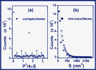 | ||
| Fig. 3 Distributions of segmented microsurfaces (a) and of their compactness (b) in the case of FC. The elementary segmentation was performed on the micrograph showed in Fig. 4a (52.19 k × magnification; full-scan threshold level). | ||
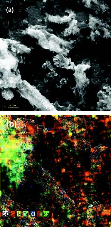 | ||
| Fig. 4 SEM micrograph of FC (a) and their chemical mapping (b). | ||
Spectroscopic measurements
The establishment of the type of functional groups carried by the nanocomposite and by its structural elements is a key factor for the prediction of the reticulation properties of the targeted pollutant group, as well as for their degradation mechanisms.The S1 suspension functionalisation strategy was built starting from the main idea which concerns the remodelling possibility of the morphochemical structure of MgX6 (X = F, O), so as we could obtain various mixtures of oxyfluorides with various functionalities.13 The change in reactivity can be obtained by replacing F and O with other functional groups, or with chemically reactive forms of (H2O)m and (NH+4)n molecular clusters. Taking into account the strategy we followed, we expect that the S1 suspension should contain both [Mg((O)(6−x)/2Fx)·(H2O)m·(NH+4)n] coordinative bonding forms and (Mg(O)(2−x)/2Fx) covalent bonding forms.14 The functional and morphochemical diversity can be due to polyanionic polymerization, polyanionic condensation or to the coordination of other types of functionalities at the level of MgX6 unoccupied or unbound sites.
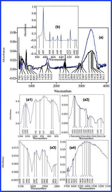 | ||
Fig. 5 IR spectra of the S1 dehydrated suspension (a) (black line – fabricated from MgCl2·6H2O![[thin space (1/6-em)]](https://www.rsc.org/images/entities/char_2009.gif) : :![[thin space (1/6-em)]](https://www.rsc.org/images/entities/char_2009.gif) NaF = 0.05 NaF = 0.05![[thin space (1/6-em)]](https://www.rsc.org/images/entities/char_2009.gif) : :![[thin space (1/6-em)]](https://www.rsc.org/images/entities/char_2009.gif) 0.1 mol dm−3 (I); blue line - fabricated from MgCl2·6H2O 0.1 mol dm−3 (I); blue line - fabricated from MgCl2·6H2O![[thin space (1/6-em)]](https://www.rsc.org/images/entities/char_2009.gif) : :![[thin space (1/6-em)]](https://www.rsc.org/images/entities/char_2009.gif) NaF = 0.02 NaF = 0.02![[thin space (1/6-em)]](https://www.rsc.org/images/entities/char_2009.gif) : :![[thin space (1/6-em)]](https://www.rsc.org/images/entities/char_2009.gif) 0.1 mol dm−3 (II)) and oxyfluoride glass II (b). For accuracy purposes figure a1–a4 presents the main IR absorption bands of the S1 suspension (MgCl2·6H2O 0.1 mol dm−3 (II)) and oxyfluoride glass II (b). For accuracy purposes figure a1–a4 presents the main IR absorption bands of the S1 suspension (MgCl2·6H2O![[thin space (1/6-em)]](https://www.rsc.org/images/entities/char_2009.gif) : :![[thin space (1/6-em)]](https://www.rsc.org/images/entities/char_2009.gif) NaF = 0.05 NaF = 0.05![[thin space (1/6-em)]](https://www.rsc.org/images/entities/char_2009.gif) : :![[thin space (1/6-em)]](https://www.rsc.org/images/entities/char_2009.gif) 0.1 case). 0.1 case). | ||
![[double bond, length as m-dash]](https://www.rsc.org/images/entities/char_e001.gif) N and C
N and C![[double bond, length as m-dash]](https://www.rsc.org/images/entities/char_e001.gif) O bonds, resulted at the end of the functionalization processes.28 Moreover, the 2800–3000 cm−1 IR band absorption profile suggests that other forms of chemically active molecular clusters (protonated, ionized or other functionalized structures) also adsorb in this area, which was absorbed by the glutaraldehyde polymerized fractions and by the coating layer. Following this approach, the peaks of C
O bonds, resulted at the end of the functionalization processes.28 Moreover, the 2800–3000 cm−1 IR band absorption profile suggests that other forms of chemically active molecular clusters (protonated, ionized or other functionalized structures) also adsorb in this area, which was absorbed by the glutaraldehyde polymerized fractions and by the coating layer. Following this approach, the peaks of C![[double bond, length as m-dash]](https://www.rsc.org/images/entities/char_e001.gif) O bonds were counted at 1734 cm−1 (the stretching of the CO groups of carboxylic acid and non-conjugated aldehyde), 1674 cm−1 (the stretching of the CO group of conjugated aldehyde), 1584 cm−1 (the asymmetric stretching of the CO of the carboxylate group) and at 1421 cm−1 (the symmetric stretching of the CO of the carboxylate group). This evidence confirms the data reported by Margel et al. and supplies additional evidence that proves the presence of highly reactive glutaraldehyde polymers in the framework of the S2 suspension.28 Besides, the peaks centered at 1655, 1643 and 1632 cm−1 can be attributed to C
O bonds were counted at 1734 cm−1 (the stretching of the CO groups of carboxylic acid and non-conjugated aldehyde), 1674 cm−1 (the stretching of the CO group of conjugated aldehyde), 1584 cm−1 (the asymmetric stretching of the CO of the carboxylate group) and at 1421 cm−1 (the symmetric stretching of the CO of the carboxylate group). This evidence confirms the data reported by Margel et al. and supplies additional evidence that proves the presence of highly reactive glutaraldehyde polymers in the framework of the S2 suspension.28 Besides, the peaks centered at 1655, 1643 and 1632 cm−1 can be attributed to C![[double bond, length as m-dash]](https://www.rsc.org/images/entities/char_e001.gif) N (stretching) bonds, proving the successful functionalization of the Fe3O4 surface laid-down aminosilane layer. Typical absorption bands of Si–O–Si (Si–O stretching; 1177, 1138, 1097, 1075, 1065, 1056 and 1029 cm−1), Si–C (stretching at 776 cm−1) and –NH2 (at 1470 and 1585 cm−1) provide conclusive additional evidence regarding the presence of the coating layer.
N (stretching) bonds, proving the successful functionalization of the Fe3O4 surface laid-down aminosilane layer. Typical absorption bands of Si–O–Si (Si–O stretching; 1177, 1138, 1097, 1075, 1065, 1056 and 1029 cm−1), Si–C (stretching at 776 cm−1) and –NH2 (at 1470 and 1585 cm−1) provide conclusive additional evidence regarding the presence of the coating layer.
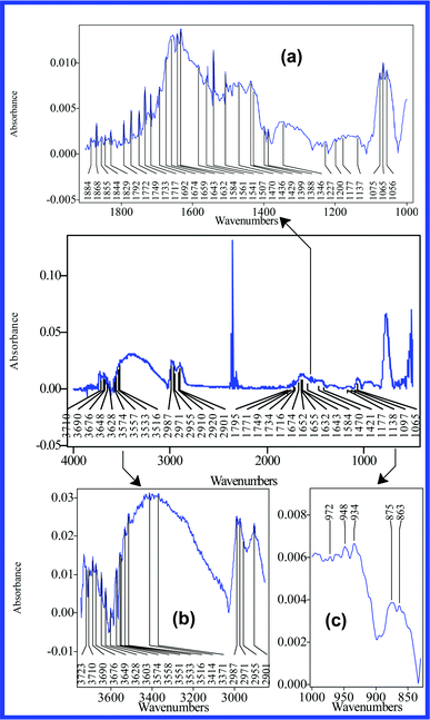 | ||
| Fig. 6 IR spectra of S2 dehydrated suspension. In order to reveal the analytical structure of their peaks, the main IR absorption bands are presented distinctly (830–1000 (c), 1000–1900 (a), 2850–3750 cm−1 (b)). | ||
![[double bond, length as m-dash]](https://www.rsc.org/images/entities/char_e001.gif) O bonds.29,30Fig. 7 presents the main functional groups expected to be grafted on the S3 framework, as well as their functionalisation mechanisms. Nitro groups can establish intramolecular bondings, since it is known that they act as strong H-bonding acceptors in solution. In the crystal state, they appear to act as very strong bases. Based on other researchers' reports (Mamede et al., Choi et al., Thomas et al.), we assign the peaks at 1458 (νas(O–NO)), 1050 (νs(O–NO)), 844 (δw(O–NO)), 548 and 559 cm−1 to nitrito and nitrosyl functional groups in the framework of the coating layer and on the surface of Fe3O4 nanoparticles.31–33 Moreover, the peaks at 1778 and 1754 cm−1 (symmetric and antisymmetric stretches of O–NO bonds) were assigned to the binuclear Fe2A2(NO)4 complexes, therefore suggesting the presence of two nitrosyl groups on the Fe3O4 nanoparticle surface (where A denotes the type of nitrosyl functional groups). This data are in accordance with the data reported by Ure et al.34
O bonds.29,30Fig. 7 presents the main functional groups expected to be grafted on the S3 framework, as well as their functionalisation mechanisms. Nitro groups can establish intramolecular bondings, since it is known that they act as strong H-bonding acceptors in solution. In the crystal state, they appear to act as very strong bases. Based on other researchers' reports (Mamede et al., Choi et al., Thomas et al.), we assign the peaks at 1458 (νas(O–NO)), 1050 (νs(O–NO)), 844 (δw(O–NO)), 548 and 559 cm−1 to nitrito and nitrosyl functional groups in the framework of the coating layer and on the surface of Fe3O4 nanoparticles.31–33 Moreover, the peaks at 1778 and 1754 cm−1 (symmetric and antisymmetric stretches of O–NO bonds) were assigned to the binuclear Fe2A2(NO)4 complexes, therefore suggesting the presence of two nitrosyl groups on the Fe3O4 nanoparticle surface (where A denotes the type of nitrosyl functional groups). This data are in accordance with the data reported by Ure et al.34
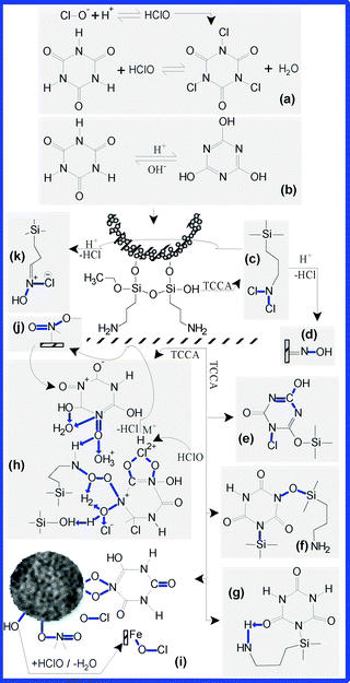 | ||
| Fig. 7 The main types of functional groups grafted in the framework structure of the S3 suspension and their probable mechanisms. In solution, TCCA releases H+ and ClO− (a) and passes into enolate form (b). The resulted chloramines (c) can be hydrolysed, resulting various oximic functionalities (d) or chloro–oximic mixtures (k). Through condensation processes, new types of functional groups may result, such as: N–Cl and C–OH in the triazinic ring (e); Si–O–N and Si–N (f); Fe–O–NO, Fe– (O)2–N– and Fe–O–Cl(I). Moreover, the amino-groups coming from the framework of coating layers may be transformed into nitrito (NO) and nitrosyl (ONO) (i and h) functionalities. The nitrogen and the oxygen can easily establish strong intramolecular hydrogen bonds or can coordinate H2O, Cl, H, or other small molecules (h), which were found as residues coming from the reaction medium, or in the framework of the composite. Additionally, the primary amines can be oxidated by HOCl, or can establish condensation reactions with the hydroxylated functionalities, leading to the appearance of groups, such as N–O–Cl and C–O–Cl (h). | ||
The peak at 1778 cm−1 (Fig. 8b), assigned to the O![[double bond, length as m-dash]](https://www.rsc.org/images/entities/char_e001.gif) C–Cl groups, resulted as a consequence of the HClO adsorption on the sites containing N
C–Cl groups, resulted as a consequence of the HClO adsorption on the sites containing N![[double bond, length as m-dash]](https://www.rsc.org/images/entities/char_e001.gif) O, N–OH and C–OH (Fig. 7h) and from TCCA. Moreover, at 1597 cm−1 we can observe a partially overlaid peak which can be assigned to the N
O, N–OH and C–OH (Fig. 7h) and from TCCA. Moreover, at 1597 cm−1 we can observe a partially overlaid peak which can be assigned to the N![[double bond, length as m-dash]](https://www.rsc.org/images/entities/char_e001.gif) O bonds (symmetrical stretching). Most likely, the O–N–O and O–N
O bonds (symmetrical stretching). Most likely, the O–N–O and O–N![[double bond, length as m-dash]](https://www.rsc.org/images/entities/char_e001.gif) O isomers were found in a stable chemical equilibrium imposed by the fabrication conditions and by the followed functionalisation strategy.
O isomers were found in a stable chemical equilibrium imposed by the fabrication conditions and by the followed functionalisation strategy.
Secondly, the Fe3O4 surface can easily react with HClO (–Fe–OH + H+ +ClO− → FeOCl + H2O) and FeOCl functionalities might result. There are two scenarios for HClO to reach the Fe3O4 nanoparticles’ surfaces: (1) directly through un-coated aminosilane layer microsites and (2) by diffusion of HClO through the depth of the coated layer framework. Thus, the peak at 503 cm−1 was attributed to FeClO bonds.35 Secondly, it is highly probable for triazinic rings to chemically interact with Si–OH, Si–O–Si and with the –(CH2)3–NH2 (Fig. 7(e, f, g, h, j)) from the aminosilane layer. The peaks at 1706 and 1699 cm−1 (Fig. 8b) have been assigned to the C![[double bond, length as m-dash]](https://www.rsc.org/images/entities/char_e001.gif) N and C
N and C![[double bond, length as m-dash]](https://www.rsc.org/images/entities/char_e001.gif) O bonds, from the triazinic rings. Moreover, in agreement with the data reported by Novozhilova et al. and Meredith et al., the typical adsorption peaks of the Fe–ON and NOO− isonitrosyl isomers (N–O stretching at 1710 cm−1) appear at 1710 and 1700 cm−1, this being a possible explanation for the high intensity and smoothing of the IR profile on the 1710–1695 cm−1 band.36,37 This evidence suggests that chlorination and oxidation are the main processes for the functionalization of the coating layer framework.
O bonds, from the triazinic rings. Moreover, in agreement with the data reported by Novozhilova et al. and Meredith et al., the typical adsorption peaks of the Fe–ON and NOO− isonitrosyl isomers (N–O stretching at 1710 cm−1) appear at 1710 and 1700 cm−1, this being a possible explanation for the high intensity and smoothing of the IR profile on the 1710–1695 cm−1 band.36,37 This evidence suggests that chlorination and oxidation are the main processes for the functionalization of the coating layer framework.
The broad band at 950–927 cm−1 acts as a fingerprint for N–Cl bonds, most likely due to the overlap of other absorption frequencies belonging to functionalities that come from the coating layer (Si–OH, Si–O–Si etc.), or from reactive molecular clusters.38 Accordingly, we observe two overlapped peaks at 944 and 937 cm−1, which were assigned to N–Cl bonds. Therefore, the N–Cl bonds can be clearly proved by the peak observed in Figure 8a as centered at 690 cm−1 (N–Cl stretching mode).39,46 Moreover, we expect that the N–Cl functionalities should also be hosted by the Fe3O4 surface (by Fe–Cl+–NH+3 bonds) owing to the physical and chemical absorption, or through the coordination processes established between ammonium ions and the unoccupied Fe ions sites. Most likely, the N–Cl bonds resulted through TCCA reticulation by -(CH2)3–NH2, or by other amino-functionalities that come from the coating layer (C–N+, –NH–, –+NH2–, – C–+NH–C, C![[double bond, length as m-dash]](https://www.rsc.org/images/entities/char_e001.gif) N+ “AF”). Additionally, we expect that Si–On+–Si and SiOn+ molecular sites might establish intramolecular or complex bonds with Cl+–NH+3, in the end resulting in –O+(–Cl+–NH+3)– morphochemical structures.
N+ “AF”). Additionally, we expect that Si–On+–Si and SiOn+ molecular sites might establish intramolecular or complex bonds with Cl+–NH+3, in the end resulting in –O+(–Cl+–NH+3)– morphochemical structures.
The peak at 844 cm−1 was assigned to Si–N bonds (stretching mode) and this can be a possible explanation for the high intensity absorption of this band. Most likely, the Si–N bonds are consequences of the hydrolysis of +(NH3)n and Si–OH groups (+(NH3)n + Si–OH → Si–NH2 + H2O + +(NH3)n−1), or of their hydrolysis in the presence of residual methoxy groups (2963 and 2815 cm−1). The band at 3500–3300 cm−1 (in Fig. 8d) contains several sharp peak clusters that have been assigned to ![[double bond, length as m-dash]](https://www.rsc.org/images/entities/char_e001.gif) N–OH functionalities, which are found in various protonated or ionized forms.40 Moreover, the peaks observed at 3207 and 3174 cm−1 have been assigned for the oximic functionalities involved in various intramolecular hydrogen bonds.41
N–OH functionalities, which are found in various protonated or ionized forms.40 Moreover, the peaks observed at 3207 and 3174 cm−1 have been assigned for the oximic functionalities involved in various intramolecular hydrogen bonds.41
The band at 3100–2850 cm−1 presents a strong adsorption and shows several sharp peaks, which were assigned to hybridized sp2 and sp3 C–H bonds (the peaks in Fig. 8c centred at 2983, 2963, 2883 and 2857 cm−1, respectively). In this region we can observe many other weak peaks or sharp overlapped bands, this evidence suggesting the presence of AF (coming from the silane layer and from the triazinic ring) and of molecular clusters. This is additional evidence which proves that the surface and the framework of the S3 suspension are hosting various functional groups found in different protonate or ionisate states.8
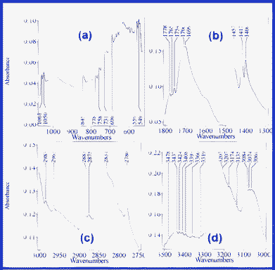 | ||
| Fig. 8 The main IR absorption bands of the S3 suspension: 530–1070 (a), 1300–1800 (b), 2750–3000 (c) and 3000–3500 cm−1 (d). | ||
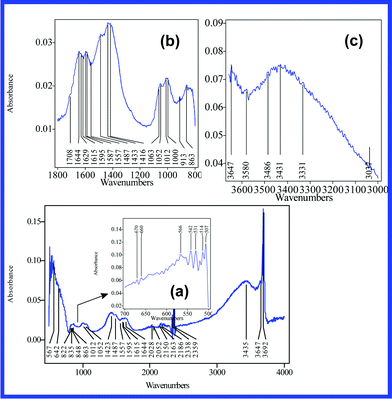 | ||
| Fig. 9 IR absorption of the fabricated nanocomposite. In order to reveal the analytical structure of their peaks, the main IR absorption bands are presented distinctly (500–700 (a), 800–1800 (b), 3000–3660 cm−1 (c)). | ||
Material testing
The absorption of chemical warfare agents on various unfunctionalized oxidic substrates (TiO2, Al2O3, zeolites etc.) has been extensively studied, using different physical techniques, especially infrared and NMR spectroscopy.50–52 The large variety of functional groups hosted by tested compounds could fit many potential applications and can simulate the chemical properties of large classes of toxic compounds and pollutants, usually present in polluted wastewater.48,49 In this work, both the composite and its structural elements have been separately tested on GB, HD and DMMP.The work-plan strategy involved the degradation of known volumes of toxic (VT) in the presence of known suspension volumes (VS). Additionally, the time degradation (tDI) was recorded. Following the previously mentioned testing strategy we performed four degradation–encapsulation tests in order to establish the encapsulation yield and efficiency of the toxic compounds. Three tests were performed without counting intermediary by-products. We quantized the total encapsulation yield and efficiency of GB and HD in the presence of the degradation nanocomposite substrate. The remnant toxic compounds were extracted using CH2Cl2 (2 mL), and counted by gas chromatography-mass spectrometry (GC-MS: using a GC of the Thermo Electron Corporation type, coupled with a MS of the DSQ II type). In test four we additionally counted and quantized the intermediary by-products, using the derivatization technique in the presence of bis(trimethylsilyl)trifluoro acetamide. In all tests we obtained the same level for the encapsulation efficiency of HD and GB. The results we obtained in test four are presented in Table 1 and Table 2. Moreover, additional tests were performed as follows: (1) 1 mL of S1 suspension degrades 26% from 3 μl yperite (96%) in 60 s; (2) 1 mL of S3 suspension degrades 20.58% from 3 μl yperite in 60 s.
| V S (mL) | V T (μL) | t D (min.) | Y D (%) |
|---|---|---|---|
| a Y D was calculated according to the [(AI-AR)/AI]·100 relation. AI and AR are the peak areas of the toxic compounds found before and after the extraction of the remnant toxic compounds. It is notable that thiodiglycol was not found in the initial sample. | |||
| S1 versus DMMP investigations | |||
| 1 | 8.5 | 1 | 36.03 |
| 1 | 2 | 37.01 | |
| 1 | 5 | 37.62 | |
| 1 | 10 | 41.51 | |
| S3 versus DMMP investigations | |||
| 1 | 8.5 | 1 | 29.51 |
| 1 | 2 | 35.05 | |
| 1 | 5 | 36.47 | |
| 1 | 10 | 38.37 | |
| FC versus DMMP investigations | |||
| 1 | 8.5 | 1 | 31.44 |
| 1 | 2 | 27.58 | |
| 1 | 5 | 27.82 | |
| 1 | 10 | 28.76 | |
| 2 | 1 | 75.35 | |
| 3 | 1 | 100 | |
| 5 | 1 | 100 | |
| FC versus HD investigations | |||
| 1 | 3 | 1 | 37.92 |
| 1 | 5 | 47.18 | |
| 2 | 10 | 92.46 | |
| 3 | 15 | 98.75 | |
| FC versus GB investigations | |||
| 1 | 3 | 2 | 24.83 |
| 2 | 2 | 38.64 | |
| 4 | 5 | 92.08 | |
| V S (mL) | V T (μL) | t DI (min.) | Y F,DI in the case of (arbitrary signal area units—a.u.) | |||
|---|---|---|---|---|---|---|
| a Y F,E was calculated in the same way as YD. In the case of DI, their typical peak area found in the initial sample was 521 a.u. Also, the typical peak areas of HM, CT and CE found in the initial samples were 637, 48, 83 a.u., respectively. | ||||||
| FC versus HD investigations | ||||||
| HM | CT | CE | T | |||
| 1 | 3 | 1 | 202 | 30 | 38 | 25.3 |
| 1 | 3 | 5 | 362 | 26 | 34.5 | 159 |
| 2 | 3 | 10 | 547 | 0 | 0 | 250 |
| 3 | 3 | 15 | 58 | 0 | 0 | 476 |
| FC versus GB investigations | ||||||
| DI | ||||||
| 1 | 3 | 2 | 489 | |||
| 2 | 3 | 2 | 450 | |||
| 4 | 3 | 5 | 76 | |||
In Fig. 10a we observe that at small volumes of the FC suspension, the degradation time (tDI) is not a significant influence for the degradation yield (YD) of DMMP. Moreover, the same behaviour can be observed in the case of the S1 and S3 suspensions, as their YD increases in the 29–42% range. In the presence of the FC substrate, the DMMP degradation yield has the tendency to diminish in the first few minutes, after which a slow increase follows in the 27.58–28.76% range. Taking into account this experimental evidence, we conclude that FC shows distinct degradation mechanisms relative to those of its structural elements. Moreover, we conclude that its degradation yield is not necessarily dependent on the density and the type of grafted functional groups. Besides, we can observe that the degradation yield increases rapidly in time only when the volume of the degradation suspension increases (Fig. 10b.). Further, this behaviour can be observed, not only in the case of the tested toxic compounds, but also in case of their degradation by-products. We also conclude that, for small VS, the toxic degradation is most likely inhibited by their degradation by-products, which deplete or block certain functionalities. We believe that, by depleting or by blocking functionalities, the catalysis processes which generate intermediary degradation by-products are stopped.
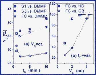 | ||
| Fig. 10 Time-dependence (a) and suspension-volume-dependence (b) of the degradation yield (YD) in the case of FC, S1 and S3 substrates. The complete degradation yield (YD(VS,tD)) for each of the investigated compounds is determined by the time (tD) and by the used suspension volumes (VS). | ||
According to the data reported by other researchers and, as we expected, in comparison with the initial degraded compounds, their intermediary degradation by-products are more easily reticulated and encapsulated by the FC substrate.41 The previously formulated conclusions are sustained by the present evidence showing that, over 1 mL of FC suspension, YD increases quickly, degrading the toxic compounds completely at about 4 mL of suspension. Accordingly, inhibition processes take place when we use less than 9.9 mg mL−1 of FC, which corresponds to a toxic charge of 3 μL (at a constant VT). Additional evidence is provided by the behaviour of HM, which is the only degradation by-product for which YD shows an inflexion point at 1 mL of the tested FC suspension (Fig. 10a and Fig. 11a). Comparatively, the rest of the degradation by-products show a small tendency for YD attenuation. That is the main reason for which we suspect that HM is responsible for the depletion and the blocking of those functionalities which favour and catalyze the degradation processes. In this context, as a conclusion of the experimental evidence (shown on Tab. 1, Tab. 2, Fig. 10, Fig.11), we conclude that toxic degradation is favoured by catalytic processes. Moreover, the encapsulation is favoured and conducted by reticulation processes.
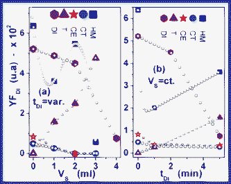 | ||
| Fig. 11 t D-dependence (b) and VS-dependence (a) of degradation yield (YF,DI) in the case of intermediary degradation by-products (the filled coloured points represent the experimentally acquired data; the empty symbol points are fits of the plotted experimental data). | ||
In Fig. 10b it is notable that YD/YF,DI shows a complicated analytical dependence, which can be described by the YD = f(VS, tD) = k·VS2·tD−β relation (with k and β as characteristic constants of each toxic), both in the case of toxic compounds, and in the case of their degradation by-products. Additionally, we observe that VS and tD establish an analytical dependence of the VS = tD−α type. We expect that α should incorporate the contribution that comes from (1) the type and density of functional groups, (2) specific intramolecular process transformations, (3) the catalytic mechanism and (4) the nature of the reticulation mechanism. By the interpolation of the data plotted in Fig. 11b, in the case of total degradation yield, we estimated the YF,DI|Y = (3.2 mL, 16 min.) and YF,DI|GB = (4.28 mL, 5.35 min.) values. The VS = tD−α dependence creates the premises for the development of specific applications of differential separation of toxic compounds. Besides, this dependence allows the control of working material consumption, the monitoring of the quantity and type of intermediary by-products, as well as control of the encapsulation-separation time.
Results and discussions
Advantages and future perspectives of smart nanomaterials
Taking into account the limitations of the current technologies of pollutant removal, one could have expected to find significant traces of toxic compounds and their degradation by-products in the collected samples. However, our experimental evidence has been confirmed by these expectations, proving that our nanocomposites have the ability to retain all tested organic compounds and their degradation by-products. Usually, CT and CE are found in yperite as remnant impurities coming from synthesis processes, while DI is a GB degradation by-product resulted by hydrolysis.41 The elucidation of these mechanisms represents a great challenge since it creates the premises for the obtaining of materials able to separate, in a controlled manner, the toxic compounds coming from environments with an imposed pH or with chemical functionality constraints. In order to explain the retention selectivity, we assumed that FC has grafted multiple chemical functionalities and, moreover, that it is strongly discretized, so that every type of functional groups is totally separated from their neighbouring functional groups, by various chemical inert microsurfaces (Fig. 12b). Secondly, the delimitation of functional groups on various host surfaces must be imposed in order to explain the preserving of the initial grafted functionality or, otherwise, it is most likely that they might interact physically or chemically.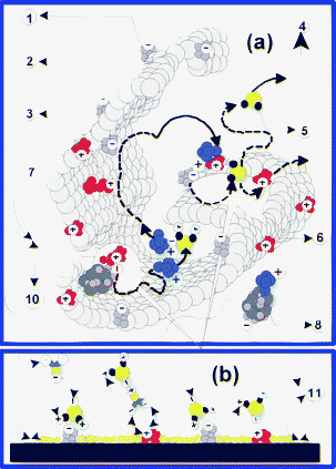 | ||
| Fig. 12 Proposed mechanisms for the transportation and reticulation of toxic compounds and their degradation by-products. The proposed mechanisms explain the chemical affinity (selectivity) of the nanocomposite towards the toxic compounds and their intermediary degradation by-products, as well as their permissive behaviour towards fluids and toxic compounds with ionic strength close to pH 7. Thus, toxic compounds can access (7) the functionalized surfaces (2) through the microcavities found in their framework. The microsites (10) with acid behaviour (3), those with base behaviour (1) or those with electric charges can reticulate the pollutants (8) in a destructive manner or by physical and chemical adsorption processes. Non-toxic molecular fractions (5) and molecular clusters can mediate mass and charge transfers between various neighbouring sites (6) or between them and the toxic compounds. In order to explain the stability of the functional structure of the composite we make the assumption that various hosted functionalities are delimited through chemically inert material microsurfaces (11). Finally, only environmentally friendly degradation by-products can leave the functionalized material (4). | ||
Chemical passivation processes have a significant role in the establishment of a stable chemical balance between microsurfaces, by removing the chemical impurities which could sustain or catalyze their functional structure degradation. As a result of the stabilization processes, the chemically reactive molecular centers favor the establishment of dynamic chemical balances between the functionalized microsurfaces and the fluids carrying the toxic compounds. It is highly probable that these balances might be materialized through charge and mass transportation between the different microsites (Fig. 12), as well as through the setting of some weak intramolecular bonds (hydrogen bonds, electrostatic adsorption, etc). Due to their mobility, molecular clusters (which favor the carrying of various toxic compounds and degradation by-products) which were previously detected by IR spectrometry are able to migrate without degrading the microsurface functionality when interacting with it. Toxic compounds can be carried into the FC framework until they are reticulated by the functional groups for which they show chemical affinity.53 Furthermore, in certain conditions, molecular clusters are able to catalyze the reticulation processes directly or they can favour the diffusion of toxic compounds into the FC framework, where they are encapsulated later on.42 Due to the localization of functional groups on solid substrates, the molecular transport events are limited in the vicinity of the framework nanoparticle microsurfaces.
Investigation of degradation and encapsulation mechanisms
In spite of the many advances in the field of toxic compound degradation, the development of sustainable, environmentally friendly technologies still remains a problem. The great challenge of the research in this field is not the degradation of toxic compounds, but the control of the degradation by-products—which can induce unexpected effects through dispersion. As we have previously formulated, the degradation of HD is led by reactive molecular clusters coming from the framework of FC. Indeed, the molecular clusters are able to form Lewis and Brønsted functionalities, distributed on the surface of oxide nanoparticles, as well as in the framework of silane and oxyfluoride coating layers. The Lewis and Brønsted sites rapidly fix the HCl and Cl− carried by the protonated forms of the molecular clusters (especially ClO− and H+) which shift the balance of hydrolysis reactions in favour of thiodiglycol formation. Secondly, data reported by other researchers prove that HM and HD are able to form intramolecular alkylated degradation by-products of the –S+–, Cl−ClS+– type (Fig. 13b).49 Most intermediary alkylated by-products are electrically charged molecular structures which can be further reticulated by physico-chemical absorption, by coordination or by replacing the functional groups coming from oxides and metal-based oxyhalide lattices. Brønsted acidic sites are generated when Fe and Mg atoms coming from oxide or oxyfluoride lattice are replaced by atoms with lower valency and a proton is attached to three coordinated oxygen atoms that connect neighbouring metal atoms. Depending on the nature of the metals, the M–OH groups created in metal fluoride or metal oxide structures may either react as a base or as a Brønsted acid. The outcome of the interchanging or replacing of functional groups (–F, –OH, ONO, MOCl, H+, NH+4, –N) is a change in basicity of metal sites. The same thing is expected to happen in the case of Brønsted acidity. The adsorption of molecular clusters on metal oxide surfaces can transform Lewis into Brønsted acidity by their dissociation and formation of Mδ+–Oδ− acid–base pairs, with the consequent creation of an M–OH acidic groups.13 Secondly, Mg–OH bonds can be Brønsted acidic when created to a very small extent in the MgF2 host phase. Due to the strong Lewis acidity, water and ammonium ions are strongly coordinated on oxyfluorides and generate strong Brønsted sites. Very small amounts of hydroxyl groups are strong Brønsted acids and very high numbers of hydroxyl groups corresponding to smaller amounts of fluorides are Brønsted bases. O2− coming from Fe3O4, MgO, Si–On+–Si, SiOn+, ONO, or other oxygen-containing sites are excellent proton acceptors that can form strong Brønsted basicity sites.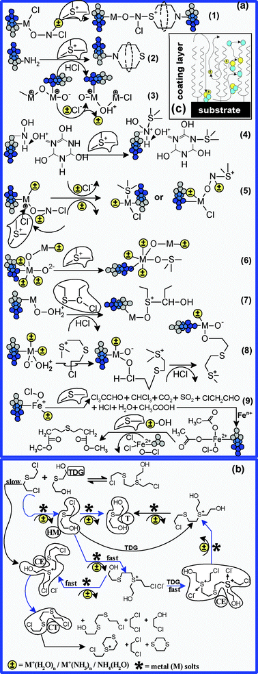 | ||
Fig. 13 Proposed degradation-encapsulation mechanisms in the case of yperite. When the water![[thin space (1/6-em)]](https://www.rsc.org/images/entities/char_2009.gif) : :![[thin space (1/6-em)]](https://www.rsc.org/images/entities/char_2009.gif) yperite ratio is over 50 yperite ratio is over 50![[thin space (1/6-em)]](https://www.rsc.org/images/entities/char_2009.gif) : :![[thin space (1/6-em)]](https://www.rsc.org/images/entities/char_2009.gif) 1, then degradation by-products are most likely to appear, as shown in diagram (b). Also, the main types of functional groups grafted in the FC framework and their most probable reticulation mechanisms are presented in diagram (a). 1, then degradation by-products are most likely to appear, as shown in diagram (b). Also, the main types of functional groups grafted in the FC framework and their most probable reticulation mechanisms are presented in diagram (a). | ||
Taking these considerations into account, it is expected that –S+– and Cl−ClS+ should establish –S–O– and –S–M bonds with O2−, Fen− (n = 1–8) and Mgm− (m = 1–8) sites, which act as strong Lewis bases (Fig. 13a(5,6)). Besides, in the context of this work, even microsites containing TCCA can reticulate –S+– and Cl−ClS+– through molecular fractions –Nm+X 3−m (X = H, OH, Cl; m = 0,1), which may interact with strong Lewis bases (Fig. 14a(4)). Secondly, we expect –Nm+X3−m not to show the same reticulation efficiency as Fen−, Mgm− or O2−, since carrying Cl− to microsurfaces containing metallic ions involves their diffusion through the coating layer laid-down on the surface of oxyde-based nanoparticles (Fig. 13c). In order to explain the analytical behaviour of the degradation–encapsulation processes presented in Fig. 10 and Fig. 11, we must admit that the diffusion of Cl− is gradually rendered difficult according to the increase in the pollutant charging degree of FC and, at the same time, in accordance with the decrease in concentration of functional structures favoring the transportation of mass and charge. First of all, it is likely that –S+– and Cl−ClS+– intermediary forms should be reticulated, their degradation and encapsulation continuing later on, both by catalytic and by reticulation processes. This can be a possible explanation for the counted tD/tDI and for the lack of other degradation by-products, which we normally expect (thiols, alcohols, etc), according to Fig. 13b. The HCl released from the intermediary degradation forms acts as a strong Brønsted acid, as it can easily give up its proton, for instance to the protonate next to the OH groups coming from Fe and Mg sites. Finally, HCl forms non-toxic metal salts (mainly by •Fe–Cl and •Mg–Cl, where • represents uncoordinated or unbounded chemically active metal substrate sites) by reaction with the surface of oxide-based substrates (Fig. 13(3)). The reaction between HCl and metallic ions sites, as well as the –S+–/Cl−ClS+– absorption into the lattice of Fe3O4 and the oxyfluoride structure can be a possible explanation for the analytical behavior of YD/YF,DI in the case of HM (Fig. 11). Moreover, we believe –S+–/Cl−ClS+– are responsible for depleting and blocking iron ions and iron sites coming from Fe3O4 lattices. Secondly, it is most likely that metal acid–base Lewis sites and interstitial anion vacancy coming from oxyde-based morphostructure are the main reactive structures responsible for the capture of S+– and Cl−ClS+–. As a result, the depletion or masking of these sites limits the encapsulation efficiency due to the inaccessibility of the sites that could host Cl− (Fig. 13c). Additionally, our hypothesis was founded on the assumption that oxidic structures show an “open surface” functional structure with “two freedom degrees” for accessing their available reticulation centres (Fig. 13c).47 We also believe that the rest of the functional groups which were identified in the framework of FC and which could capture the intermediary by-products, are found in quantities which are more than enough to compensate the depletion and blocking processes. Moreover, these functional groups can degrade toxic compounds, since they have “three freedom degrees” for accessing their available reticulation sites. In the context of this work, these are convincing arguments to consider the metal-containing ions and sites as the main factors responsible for sustaining the catalytic processes.
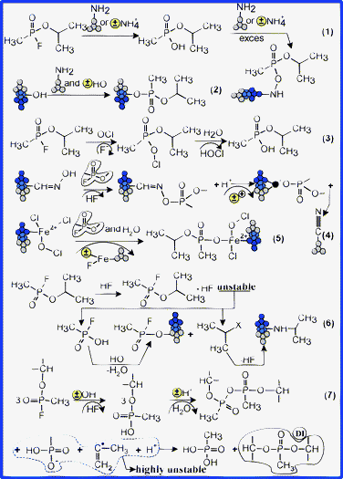 | ||
| Fig. 14 Proposed mechanisms for GB degradation and encapsulation. | ||
As we can observe in Fig. 13a, most intermediary by-products are chlorinated compounds, and it is likely that they are be quickly encapsulated in the framework of FC by reticulation of amino-fractionalities coming from coating substrates (Fig. 13(1,2)). Other routes for HD degradation are provided by metal oxychlorides (especially FeOCl) and acid chlorides functionalities, providing CCl3CCHO, CHCl3, CO2, SO2, ClCH2CHO, HCl, H2O and CH3COOH (Fig. 13a(9)). The acetic acid can quickly form metallic salts which continue the degradation of HD with the cumulation of methylic esters (Fig. 13(9)). Later, the metallic esters of HD can be easily encapsulated by condensation in the presence of other functional groups (mainly –OH).
As a halogen anhydride, GB can acylate a large number of reactive groups, such as –OH, –NH2 and =NOH. Most likely, a significant fraction of GB was degraded by hydrolytic processes, in the presence of reactive molecular clusters of amino-functionalities or in the presence of ClO− ions (Fig. 14(1,3)). Otherwise, in basic degradation conditions and with amino-functionality excess, GB can be directly encapsulated by sites containing TCCA and by the silane coating layer. Following the hydrolysis, in the presence of Lewis acid sites, the resulting O-isopropyl methylphosphonic acid (IMPA) is also rapidly encapsulated by the formation of esteric bonds with FC substrates (Fig. 14(1,2)). A small part of the resulting HF further degrades the GB (Fig. 14(6)), the rest forming non-toxic salts with metal sites, with NH+4(H2O)n and M+(NH3)n, or with amino-functionalities. Secondly, the oximic groups (C![[double bond, length as m-dash]](https://www.rsc.org/images/entities/char_e001.gif) NOH, M–NOH, M–ONOH; M
NOH, M–NOH, M–ONOH; M![[double bond, length as m-dash]](https://www.rsc.org/images/entities/char_e001.gif) Fe, Mg) can form strong CH3POO− (OCH(CH3)2) Brønsted bases (Fig. 14(4)), which are able to reticulate Brønsted acid sites.
Fe, Mg) can form strong CH3POO− (OCH(CH3)2) Brønsted bases (Fig. 14(4)), which are able to reticulate Brønsted acid sites.
The appearance of DI is conclusive evidence which explains the forming of intramolecular dimerised [CH3POO− (OCH(CH3)2)]2 forms as a result of IMPA co-hydrolysis in the presence of Brønsted acid sites (Fig. 14(7)). Moreover, according to our proposed degradation mechanism, it is likely that, following the co-hydrolysis processes, very unstable intermediary by-products might result, which are rapidly captured by the functional structure of oxyde-based substrates (mainly by Lewis–Brønsted base sites). On the other hand, the CH2![[double bond, length as m-dash]](https://www.rsc.org/images/entities/char_e001.gif) C˙–CH3 radicals may be reticulated rapidly on the surface of Brønsted acid sites, or may interact with protonate forms of the molecular clusters, forming various addition compounds. Moreover, these radicals may reticulate metal Lewis acid sites coming from the framework of oxide-based nanostructures.
C˙–CH3 radicals may be reticulated rapidly on the surface of Brønsted acid sites, or may interact with protonate forms of the molecular clusters, forming various addition compounds. Moreover, these radicals may reticulate metal Lewis acid sites coming from the framework of oxide-based nanostructures.
Additionally, GB can directly reticulate nanoparticle substrates, by forming salts with the iron ions due to the vacancies induced in the Fe3O4 lattices by HF (Fig. 14(5)). Most likely, in the first stage, the oximic groups, the metallic ions and the amino-groups (coming from coating layer and from TCCA), rapidly capture toxic compounds.
In the case of DMMP degradation (Fig. 15), we can observe that, compared to HD and GB, the total encapsulation efficiency rapidly increases, even at small VS. Having two types of functionalities (P–O–C and P![[double bond, length as m-dash]](https://www.rsc.org/images/entities/char_e001.gif) O), DMMP can be reticulated mainly by hydrolysis (Fig. 16(2)) and absorption processes on Lewis acid sites (Fig. 16(2)). Most probably, GB and their by-products are catalyzed mainly by Brønsted acid sites and the –OH groups from the surface and depth of the nanocomposite framework. The resulting CH3OH and −O–P–O− radicals may be later reticulated on the metal-oxide microsurfaces (Fig. 16(1)). Secondly, experimental evidence suggests that the P–O–C hydrolysis processes and those of adsorption (typical −O–P–O−) occur quite rapidly. Accordingly, we believe it is likely that the degradation of partially degraded reticulated-encapsulated compounds might occur afterwards, without releasing the already reticulated fractions of toxic.
O), DMMP can be reticulated mainly by hydrolysis (Fig. 16(2)) and absorption processes on Lewis acid sites (Fig. 16(2)). Most probably, GB and their by-products are catalyzed mainly by Brønsted acid sites and the –OH groups from the surface and depth of the nanocomposite framework. The resulting CH3OH and −O–P–O− radicals may be later reticulated on the metal-oxide microsurfaces (Fig. 16(1)). Secondly, experimental evidence suggests that the P–O–C hydrolysis processes and those of adsorption (typical −O–P–O−) occur quite rapidly. Accordingly, we believe it is likely that the degradation of partially degraded reticulated-encapsulated compounds might occur afterwards, without releasing the already reticulated fractions of toxic.
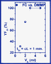 | ||
| Fig. 15 V S-dependence of YF,DI (DMMP case). | ||
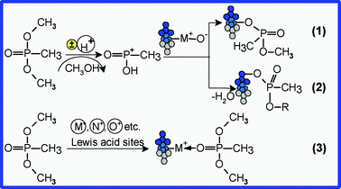 | ||
| Fig. 16 Proposed mechanisms for DMMP encapsulation. | ||
Conclusions
In summary, we have fabricated a functionalized nanocomposite material for the highly efficient degradation and encapsulation of a large number of toxic organic compounds. The material was tested on HD, GB and DMMP, in order to investigate their degradation–encapsulation yield and efficiency, as well as their intermediary degradation by-products. Intermediary by-products were counted and quantized by GC-MS. The following results have been found: (1) The fabricated nanocomposite incorporates three different types of functionalized coated nanoparticles and was successfully built in the presence of trichloroisocyanuric acid. Additionally, we have proved that the nanocomposite preserves the morphostructure of its structural elements. Moreover, the structural elements are strongly discretized and show agglomeration domains in the 63–920 nm2 range. (2) The nanocomposite material shows multiple-functionality, which is preserved at the end of the fabrication process. The main functional groups grafted on the surface and in the depth of the nanocomposite framework are: chemically active molecular clusters ((H2O)m, (NH+4)n, M+(H2O)n, M+(NH3)n, NH+4(H2O)n; M![[double bond, length as m-dash]](https://www.rsc.org/images/entities/char_e001.gif) Fe, Mg); open surface metal-oxide sites grafted with acid–base Brønsted and Lewis functionalities (Mg–O, Fe–O, Fe–O–Fe); open surface metal anion-cation sites grafted with acid–base Brønsted and Lewis functionalities (•Fe±, •Mg±); Mg–F; MgOH; C
Fe, Mg); open surface metal-oxide sites grafted with acid–base Brønsted and Lewis functionalities (Mg–O, Fe–O, Fe–O–Fe); open surface metal anion-cation sites grafted with acid–base Brønsted and Lewis functionalities (•Fe±, •Mg±); Mg–F; MgOH; C![[double bond, length as m-dash]](https://www.rsc.org/images/entities/char_e001.gif) N; C
N; C![[double bond, length as m-dash]](https://www.rsc.org/images/entities/char_e001.gif) O; C–O; C–O–Cl; –NH2; O–N; N
O; C–O; C–O–Cl; –NH2; O–N; N![[double bond, length as m-dash]](https://www.rsc.org/images/entities/char_e001.gif) O; N–Cl; C–OH; Si–N; Si–On+–Si; SiOn+; N–O–Cl; N–OH; Fe–O–NO; Fe– (O)2–N–; Fe–O–Cl; Fe–ON. Additionally, we have proved that our composite has a high degree of structural and functional stability—experimental evidence does not confirm the presence of toxic compounds, degradation by-products or other fractions coming from their framework structure. (3) The tested material is able to reticulate undifferentiated toxic organic compounds and their degradation by-products. Additionally, the material can encapsulate toxic organic compounds and can also release environmentally friendly degradation by-products. The material was capable of the complete degradation and encapsulation of the tested toxic compounds in less than 16, 5.35, and 1 min for HD, GB, DMMP, respectively. Moreover, we observe that all degradation by-products have been completely encapsulated, even more rapidly than the degraded toxic compounds. (4) It was observed that the encapsulation processes can be described by a set of process variables (VS, tD). We have proved that this set is unique for each type of toxic compound. Improvement of the encapsulation yield (YF,DI) can be achieved by successive variation of VS and tD. In the case of total degradation, for HD and GB we found YF,DI|Y = (3.2 mL, 16 min.) and YF,DI|GB= (4.28 mL, 5.35 min.) (5) We proposed and analysed mechanisms for the reticulation, degradation and encapsulation of selected toxic compounds as well as their degradation by-products. We conclude that reactive molecular clusters, as well as Brønsted and Lewis sites are responsible for catalysis and for degradation rate. Functional groups, metal atoms and metal ion sites coming from the framework of the composite, have a significant role in the reticulation and encapsulation processes of toxic compounds and of their degradation by-products.
O; N–Cl; C–OH; Si–N; Si–On+–Si; SiOn+; N–O–Cl; N–OH; Fe–O–NO; Fe– (O)2–N–; Fe–O–Cl; Fe–ON. Additionally, we have proved that our composite has a high degree of structural and functional stability—experimental evidence does not confirm the presence of toxic compounds, degradation by-products or other fractions coming from their framework structure. (3) The tested material is able to reticulate undifferentiated toxic organic compounds and their degradation by-products. Additionally, the material can encapsulate toxic organic compounds and can also release environmentally friendly degradation by-products. The material was capable of the complete degradation and encapsulation of the tested toxic compounds in less than 16, 5.35, and 1 min for HD, GB, DMMP, respectively. Moreover, we observe that all degradation by-products have been completely encapsulated, even more rapidly than the degraded toxic compounds. (4) It was observed that the encapsulation processes can be described by a set of process variables (VS, tD). We have proved that this set is unique for each type of toxic compound. Improvement of the encapsulation yield (YF,DI) can be achieved by successive variation of VS and tD. In the case of total degradation, for HD and GB we found YF,DI|Y = (3.2 mL, 16 min.) and YF,DI|GB= (4.28 mL, 5.35 min.) (5) We proposed and analysed mechanisms for the reticulation, degradation and encapsulation of selected toxic compounds as well as their degradation by-products. We conclude that reactive molecular clusters, as well as Brønsted and Lewis sites are responsible for catalysis and for degradation rate. Functional groups, metal atoms and metal ion sites coming from the framework of the composite, have a significant role in the reticulation and encapsulation processes of toxic compounds and of their degradation by-products.
Accordingly, we conclude that nanocomposite materials with multiple-functionalized structures are promising solutions in the field of wastewater treatment. These materials favour the achievement of inexpensive, smart solutions for: (1) the removal of toxic and very toxic organic compounds after wastewater treatments, (2) the development of novel, inexpensive technologies for pollutant separation, (3) the decontamination of ground and surface waters, (4) the development of novel, environmental friendly biodegradable materials, etc. Besides, using mixtures of natural oxides and following the same strategy as the one utilised in this work, we reported the fabrication of a novel, smart biodegradable material, able to encapsulate a significant number of organic pollutants, coming from various types of wastewaters.44,45
Acknowledgements
We acknowledge the full support of the Scientific Research Center for CBRN Defense and Ecology. We are also indebted to Loredana Iordache for her helpful linguistic advice. We also thank Professor Bojin Dionesie from the Faculty of Engineering in Foreign Languages and Faculty of Applied Chemistry and Material Science (University Politehnica of Bucharest) for his kind assistance in providing TEM investigation.References
- P. R. Gogate and A. B. Pandit, Adv. Environ. Res., 2004, 8(3–4), 501 CrossRef CAS.
- A. Al-Kdasi, A. Idris, K. Saed and C. T. Guan, GLOBAL NEST: the International Journal, 2004, 6(3), 222 Search PubMed.
- N. P. Cheremisinoff, in Handbook of water and wastewater treatment technologies, Butterworth-Heinemann Publishing, Boston, 2002 Search PubMed.
- J. Bratby, in Coagulation and Flocculation in Water and Wastewater Treatment, IWA Publishing, London, 2006 Search PubMed.
- T. Robinson, G. McMullan, R. Marchant and P. Nigam, Bioresour. Technol., 2001, 77(3), 247 CrossRef CAS.
- D. W. Tedder and F. G. Pohland, in Emerging Technologies in Hazardous Waste Management (ACS Symposium Series), American Chemical Society Publishing, Washington DC, 1990. Search PubMed.
- N. Savage, M. Diallo, J. Duncan, A. Street and R. Sustich, in Nanotechnology applications for clean water, William Andrew Inc. Publishing, Norwich, 2009 Search PubMed.
- M. Mookherjee, S. A. T. Redfern, M. Zhang and D. E. Harlov, Eur. J. Mineral, 2002, 14, 1033–1039 CrossRef CAS.
- A. Cassano, R. Molinari, M. Romano and E. Drioli, J. Membr. Sci., 2001, 181(1), 111 CrossRef CAS.
- J. Theron, J. A. Walker and T. E. Cloete, Crit. Rev. Microbiol., 2008, 34(1), 43 CrossRef CAS.
- P. Gómez-Romero and C. Sanchez, in Functional Hybrid Materials, WILEY-VCH Publishing, Weinheim, 2004 Search PubMed.
- A. K. Jain, in Fundamentals of Digital Image Processing, Prentice-Hall Publishing, New Jersey, 1989. Search PubMed.
- A. Tressaud, in Functionalized Inorganic Fluorides – Synthesis, Characterization & Properties of Nanostructured Solids, Wiley Publishing, West Sussex, United Kingdom, 2010 Search PubMed.
- R. L. Withers, F. J. Brink, Y. Liu and L. Norén, Polyhedron, 2007, 26, 290 CrossRef CAS.
- U. Schwertzmann and H. Thalmann, Clay Miner., 1976, 11, 189 Search PubMed.
- I. A. Katsoyiannis and A. I. Zouboulis, Water Res., 2004, 38, 17 CrossRef CAS.
- A. M Hofmeister, E. Keppel and A. K. Speck, Mon. Not. R. Astron. Soc., 2003, 345, 16 CrossRef.
- M. Yamaura, R. L. Camilo, L. C. Sampaio, M. A. Mac, M. Nakamura and H. E. Toma, J. Magn. Magn. Mater., 2004, 279, 210 CrossRef CAS.
- V. P. Tolstoy, I. V. Chernyshova, V. A. Skryshevsky, in Handbook of Infrared Spectroscopy of Ultrathin Films, Wiley Interscience Publishing, New Jersey, USA, 2003 Search PubMed.
- S. Wuttke, S. M. Coman, J. Kröhnert, F. C. Jentoft and E. Kemnitz, Catal. Today, 2010, 152, 2 CrossRef CAS.
- M. Sterrer, T. Risse and H. J. Freund, Surf. Sci., 2005, 596, 222 CrossRef CAS.
- A. Pelmenschikov, G. Morosi and A. Gamba, J. Phys. Chem. B, 2000, 104, 11497 CrossRef CAS.
- G. Wu, X. Wang, B. Chen, J. Li, N. Zhao, W. Wei and Y. Sun, Appl. Catal., A, 2007, 329, 106 CrossRef CAS.
- W. Hu, C. T. Johnston, P. Parker and S. F. Agnew, Clay. Clay. Miner., 2000, 48, 120 Search PubMed.
- J. I. Lee, D. C. Sperry and J. M. Farrar, J. Chem. Phys., 2004, 121(7), 8375 CrossRef CAS.
- K. Nakamoto, in Infrared and Raman Spectra of Inorganic and Coordination Compounds, 6th ed., Wiley Publishing, New Jersey, 2009 Search PubMed.
- J.-C. Jiang, Y.-S. Wang, H.-C. Chang, S. H. Lin, Y. T. Lee, G. Niedner-Schatteburg and H.-C. Chang, J. Am. Chem. Soc., 2000, 122, 1398 CrossRef CAS.
- S. Margel and A. Rembaum, Macromolecules, 1980, 13, 19 CrossRef CAS.
- E. Colvari, A. Ghorbani-Choghamarani, P. Salehi, F. Shirini and M. A. Zolfigol, J. Iran. Chem. Soc., 2007, 4(2), 126 CrossRef.
- N. Xu, J. Yi and G. B. R. Addo, Inorg. Chem., 2010, 49, 6253 CrossRef CAS.
- A. S. Mamede, G. Leclercq, E. Payen, P. Granger and J. Grimblot, J. Mol. Struct., 2003, 651–653, 353 CrossRef CAS.
- J. H. Choi, I. G. Oh, W. T. Lim, K. S. Ryoo, D. I. Kim and Y. C. Park, J. Korean Chem. Soc., 2005, 49(2), 239–242 CrossRef CAS.
- M. R. Thomas, D. Brown, S. Franzen and S. G. Boxer, Biochemistry, 2001, 40, 15047 CrossRef CAS.
- A. M. Ure and C. M. Davidson, in Chemical Speciation in the Environment, 2nd ed., Blackwell Science Publishing, Abingdon, 2002 Search PubMed.
- Z. I. Takera, H. Sakaebe and K. Kanamura, J. Power Sources, 1993, 44(1–3), 627 CrossRef.
- I. V. Novozhilova, P. Coppens, J. Lee, G. B. Richter-Addo and K. A. Bagley, J. Am. Chem. Soc., 2006, 128, 2093 CrossRef CAS.
- C. Meredith, R. D. Davy, G. E. Quelch and H. F. Schaefer III, J. Chem. Phys., 1991, 94(2), 1317–1326 CrossRef CAS.
- B. T. Gowda, J. D. D'Souza and B. H. A. Kumar, Z. Naturforsch., 2003, 58a, 51–56 Search PubMed.
- T. Egawa, M. Ito and S. Konaka, J. Mol. Struct., 2001, 560, 337 CrossRef CAS.
- R. Llanguri, J. J. Morris, W. C. Stanley, E. T. Bell-Loncella, M. Turner, W. J. Boyko and C. A. Bessel, Inorg. Chim. Acta, 2001, 315, 53 CrossRef CAS.
- T. C. Marrs, R. L. Maynard, F. R. Sidell, in Chemical Warfare Agents - Toxicology and Treatments, 2nd ed., Wiley Publishing, New Delhi, India, 2007 Search PubMed.
- J. A. Schwarz and C. I. Contescu, in Surfaces of Nanoparticles and Porous Materials, Marcel Dekker Publishing, New York, USA, 1999 Search PubMed.
- C. Flego and L. Dalloro, Microporous Mesoporous Mater., 2003, 60, 263 CrossRef CAS.
- N. Petrea, P. Z. Iordache, R. M. Lungu, I. Safta, R. Petre and A. Pretorian, New Methods and New Types of Functionalized Nanocomposites Intended for the Ecological Depollution of Waters in Nanomaterials, Intech Publishing, Rijeka, Croatia, 2011 Search PubMed.
- P. Z. Iordache, N. Petrea, R. M. Lungu, R. Petre, C. Său and I. Safta, Nanocomposite Materials with Oriented Functionalized Structure in Nanomaterials, Intech Publishing, Rijeka, Croatia, 2011 Search PubMed.
- R. Murugesan and E. Subramanian, Bull. Mater. Sci., 2002, 25(7), 613 CrossRef CAS.
- C. I. Contescu and J. A. Schwartz, Acid–Base Behaviour of Surfaces of Porous Materials, in Surfaces of Nanoparticles and Porous Materials, Marcel Dekker Publishing, New York Basel, USA, 1999 Search PubMed.
- S. L. Burtelt-Hunt, D. R. U. Knappe and M. A. Barlaz, Crit. Rev. Environ. Sci. Technol., 2008, 38, 112 CrossRef.
- G. O. Bizzigotti, H. Castelly, A. M. Hafez, V. H. B. Smith and M. T. Whitmire, Chem. Rev., 2009, 109, 236 CrossRef CAS.
- K. Kim, O. G. Tsay, D. A. Atwood and D. G. Churchill, Chem. Rev., 2011, 111, 5345 CrossRef CAS.
- V. M. Bermudez, J. Phys. Chem. C, 2009, 113, 1917 CAS.
- Q. Meng, D. C. Doetschman, A. K. Rizos, M.-H. Lee, J. T. Schulte, A. Spyros and C. W. Kanyi, Environ. Sci. Technol., 2011, 45, 3000 CrossRef CAS.
- T. Zecheru, T. Rotariu, E. Rusen, B. Mărculescu, F. Minculescu, L. Alexandrescu, I. Antoniac and I.-C. Stancu, J. Mater. Sci.: Mater. Med., 2010, 21(10), 2793–2804 CrossRef CAS.
- Y.-S. Wang, H.-C. Chang, J.-C. Jiang, S. H. Lin, Y. T. Lee and H.-C. Chang, J. Am. Chem. Soc., 1998, 120, 8777–8788 CrossRef CAS.
Footnote |
| † These authors contributed equally. |
| This journal is © The Royal Society of Chemistry 2012 |
