[FeFe]-hydrogenase-inspired membrane electrode and its catalytic evolution of hydrogen in water†
Enbin
Xu
ab,
Zhiyin
Xiao
b,
Haiqing
Liu
b,
Li
Long
b,
Lei
Li
ab and
Xiaoming
Liu
*ab
aSchool of Petrochemical Engineering, Changzhou University, Changzhou, 213164, China
bCollege of Biological, Chemical Sciences and Engineering Jiaxing University, Jiaxing, 314001, China. E-mail: xiaoming.liu@mail.zjxu.edu.cn; Fax: +86 (0)573 83643937; Tel: +86 (0)573 83643937
First published on 4th September 2012
Abstract
A membrane electrode assembled with electrospun-fibers derived from a composite of cellulose acetate (CA) functionalised with carboxylated multiwall carbon nanotubes (cMWCNTs), polyvinyl pyrrolidone (PVP), and diiron model ([Fe2(edt)(CO)6], edt = ethanedithiolate) catalyses proton reduction in water with the presence of acetic acid.
It is widely accepted that hydrogen is a promising energy vector to replace fossil fuels in the future. But, to make hydrogen our major energy source practicably possible, one of the big challenges we need to take on is how to produce hydrogen with low cost and sufficient efficiency. In this regard, finding an effective and readily available catalyst will have pivotal significance. But to date, precious metals, platinum and palladium, have been the only category of the most effective catalysts in the catalytic production of hydrogen in industry. But these metals are in extremely low abundance in the crust of our planet. However, in nature, a category of metalloenzymes called hydrogenases, exists in many algae and microbes.1,2 These enzymes catalyze both evolution and oxidation of hydrogen at remarkable efficiency and rate.2 Another distinct feature of the enzymes is that the enzymatic catalysis operates in aqueous solution at physiological conditions with no overpotential.
[FeFe]-hydrogenase is one member of the enzymatic family, whose precise structure was solved over a decade ago, Fig. 1.3,4 Revelation of the structure of the enzyme has stimulated intense research interest in mimicking the active site, particularly the diiron subunit, due to the relevance to hydrogen energy.5–15 In the past years, our group has also been intensively involved in this fascinating chemistry.16–24 But among the reported systems, only a few could be investigated in aqueous solution due to their insolubility in water.25–27 This is in sharp contrast to the natural system. The insolubility of the synthesized systems in water is one of the obstacles which have hindered advancing this mimicking chemistry further towards practical application in catalytic hydrogen production. Moreover, assembling synthetic models into electrodes operational in water is even more challenging. But this is a vital step towards applying the bio-inspired diiron complexes to catalytic evolution of hydrogen.
![Schematic view of the H-cluster of the [FeFe]-hydrogenase.](/image/article/2012/RA/c2ra21036c/c2ra21036c-f1.gif) | ||
| Fig. 1 Schematic view of the H-cluster of the [FeFe]-hydrogenase. | ||
Compared to the tremendous reports of synthetic diiron mimics as summarized in those reviews,5–15 fabricating electrodes using diiron mimics has been quite underdeveloped. To date, only limited effort has been devoted to this aspect.22–24,28–31 In our group, different approaches have been adopted to assemble electrodes using polymers functionalized with diiron models.21–24 All those polymers could be assembled into film electrodes using appropriate approaches, namely chemical immobilization and spin-coating. But to prepare electrodes possessing robustness and hydrophilicity remain problematic. Operation in water was simply impossible since all those materials are hardly hydrophilic. Thus, novel approaches are still desired to develop functional materials with which electrodes with appropriate robustness, hydrophilicity, and catalytic functionality could be assembled.
Electrospun-fibres prepared under high voltage from readily available materials, for example, cellulose acetate, usually show good hydrophilicity, high specific area and excellent permeability.32–34 Herein, we report the preparation of a cellulose acetate-based electrospun-fibre containing diiron model, assembling of the membrane electrode using the materials and its catalysis on proton reduction in water. In addition to its operation in water, the assembled membrane electrode also showed greatly improved stability compared to those reported previously.22–24,28–31
The composite for electrospinning consisted of cellular acetate functionalized with cMWNCTs (CA-cMWCNTs), polyvinyl pyrrolidone (PVP) (Fig. 2a), and the diiron model complex in dimethylacetamide (DMAc). As a preliminary attempt, a diiron model readily available, [Fe2(edt)(CO)6] (edt = ethanethiolate, Fe2), was employed. Since both CA and PVP are non-conductive, carboxylated multiwall carbon nanotubes (cMWCNTs) were chemically grafted onto CA at ca. 2% by converting the carboxyl group into acyl chloride. The successful fictionalization was confirmed by the comparison between the behaviours of a mechanically mixed composite of CA + cMWCNTs and the functionalised material CA-cMWCNTs in DMAc, Fig. S1.† The former showed clearly two phases whereas the latter maintained an even dispersion after standing for a period of time. The structures of these substances are illustratively shown in Fig. 2a. In Fig. 2b is shown the photograph of the electrospun-fibre membrane (EFM-Fe2) whose intense yellow originated from the diiron complex (Fe2).
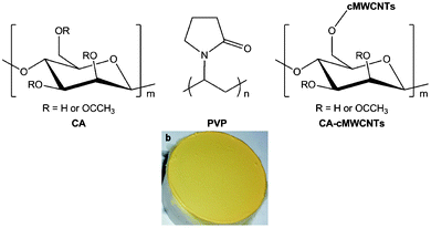 | ||
| Fig. 2 (a) CA, PVP, and schematic view of CA-cMWCNTs, (b) the photograph of the electrospun-fibers membrane (CA: 52%; PVP: 18%, cMWCNTs: 2%, Fe2: 28%, working voltage: 9.77 kV, collecting distance: 15 cm, flowing rate: 1.5 mL h−1, T = 30 °C, humidity: 80%, collecting time: 15 min., the diameter of the disc-collector: 5 cm). | ||
As revealed by the SEM images (Fig. S2†), the diameters of the electrospun-fibres are at the scale of hundreds of nanometers (approximately in the range of 200–300 nm) and the thickness of the membrane was estimated at the scale of hundreds of micrometers. The entire membrane is full of lacunas ranging from hundreds of nanometers to micrometer, which ensured membrane high permeability. Since the model is insoluble in water, its dispersion in the electrospun-fibres ought to rely on the hydrophobic interaction between the mimic and the hydrophobic moieties of the fibres. Infrared spectral profiles of the membrane indicated that the incorporated diiron complex retained the integrity of its diiron hexacarbonyl core in the membrane, Fig. 3. Thermal gravimetric analysis (TGA) showed essentially a similar decomposing pattern to those reported previously,21–24 Fig. S3.†
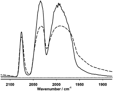 | ||
| Fig. 3 Diffuse reflection infrared spectra of model complex Fe2 (dash line), the electrospun-fibres membrane containing the diiron model (EFM-Fe2, solid line) and the membrane without the model (CA-cMWCNTs + PVP, dotted line). | ||
To assemble an electrode, a piece of the electrospun-fibre membrane was cut off using a paper punch (ϕ = 6 mm) and then the round-shaped electrospun-fibre membrane was transferred onto the surface of a vitreous carbon electrode (ϕ = 5 mm) which was freshly polished and moisturized. The assembled electrode was dried in air and its electrochemistry was performed in aqueous KCl (0.1 mol L−1). As indicated in Fig. 4, the electrode showed an electrochemical response at about −1.3 V at which both the bare vitreous carbon and the control electrode showed no signals. Furthermore, the peak potential is comparable to that of complex Fe2 in acetonitrile (Fig. S3†). Therefore, the reduction process at −1.3 V is assigned to the reduction of the diiron model complex Fe2 dispersed in the electrospun-fibres. The electrochemical activity of the electrode suggested that electron transfer between the interfaces, vitreous carbon electrode/the electrospun-fibres/water, was well maintained. This is undoubtedly attributed to the chemical immobilization of cMWCNTs onto the cellulose acetate material, its strong hydrophilicity of the matrix material, and the high permeability of the electrospun-fibre membrane.
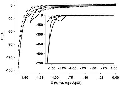 | ||
| Fig. 4 Electrochemical responses of bare vitreous carbon electrode (dotted line), CA-cMWCNTs + PVP electrode (the control electrode, dash line) and EFM-Fe2 electrode (solid line) in 0.1 mol L−1 KCl–H2O (3.5 mL, room temperature, scanning rate = 0.1 V s−1). Inset: the electrochemical responses of the electrodes in the presence of 2 μL of acetic acid solution (20%). | ||
In sharp contrast to the electrodes we reported before,22–24 the membrane electrode assembled with the electrospun-fibres showed remarkable improvement in stability. Rather than losing almost any electrochemical response after only one scanning, the electrode retained electrochemical activity by about 50% after repetitive scanning (150 cycles) as indicated by both the intensities of the infrared spectroscopic absorption bands (Fig. S4†) and the reduction peak current (Fig. S5†). For the electrodes reported previously, they lost electrochemical activity due to two causes, (i) insufficient catalytic centres in the membrane and one scan was enough to “kill” the electrode22 and (ii) while enough catalytic diiron units might be presented, decomposed product(s) from the irreversible reduction of the diiron centre formed an “insulating” layer at the interface between the matrix electrode and the membrane might block the electron transfer crossing the interface.23,24 For the electrode reported in this work, the loading (28%, please refer to ESI† for further information) of the diiron mimics was greatly improved. Moreover, the excellent permeability of the membrane (Fig. S2†) would surely minimize the formation of an insulating layer from any decomposed product(s). Thus, the remaining diiron units on the surface of the fibres remained active and the mimics evenly dispersed in the electrospun-fibres kept the electrode active against repetitive scanning. The stability of the assembled electrode was also assessed by immersing the functionalised electrospun-fibre membrane in an acidic solution. It turned out that the intensity of infrared absorption bands remained ca. 30% after being immersed for 34 h, Fig. 5.
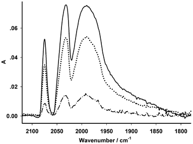 | ||
| Fig. 5 Spectral variation of the electrospun membrane, EFM-Fe2, after being immersed in 0.1 mol L−1 KCl/H2O (3.5 mL, 298 K) in the presence of 2 μL of acetic acid (20%) for various hours (solid line: 0 h, dot line: 14 h, dash-dot line: 34 h). | ||
The significant improvement in stability allowed us to further examine how the electrodes respond to the addition of acetic acid in water using the same electrode. Due to instability, such an examination had not been possible previously.22–24,28–31 As shown in Fig. 6, the electrode exhibited positive responses to the addition of acetic acid (20%). Compared to the electrochemistry of the control electrode in which the membrane electrode possessed no diiron mimics, Fig. 4 (inset) and Fig. 6, the reduction process can be confidently assigned to the catalytic reduction of protons. To assess the electrocatalytic efficiency and overpotential for proton reduction, the electrochemistry and catalysis on proton reduction of a shiny Pt-disc electrode was examined under the same conditions, Fig. 7. Compared to the assembled electrode (Fig. 5, inset), the Pt-disc electrode exhibited higher catalytic efficiency by ca. 60% whereas the overpotential was 400 mV lower. Attempts using bulk electrolysis in the presence of excessive acetic acid to estimate TON/TOF was not successful because vigorously evolving hydrogen damaged the membrane. Part of the membrane was blown off the surface of the vitreous carbon electrode during the bulk electrolysis.
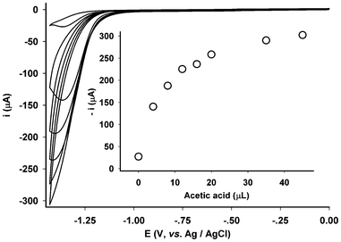 | ||
| Fig. 6 Proton reduction at the electrode (EFM-Fe2) with various concentrations of added successively acetic acid (20%, 0, 4, 8, 12, 16, 20, 35, 45 μL) in 0.1 mol L−1 KCl/H2O (3.5 mL, 298 K, scanning rate = 0.1 V s−1). | ||
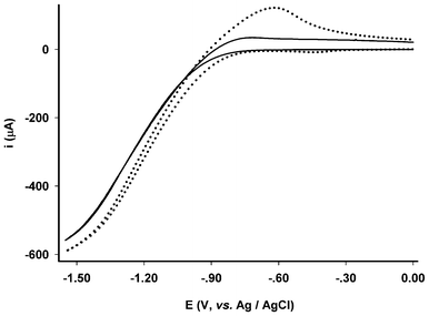 | ||
| Fig. 7 Electrochemical responses of bare Pt disc electrode (ϕ = 5 mm) in 0.1 mol L−1 KCl/H2O (3.5 mL, room temperature, scanning rate = 0.1 V s−1) with absence (solid line) and presence (dot line) of 2 μL of acetic acid (20%). | ||
In summary, a novel approach of assembling a catalytic membrane electrode inspired by the mimicking chemistry of [FeFe]-hydrogenase was described. The membranes were prepared through electrospinning a composite of CA-cMWCNTs, PVP, and the diiron mimic of the subunit of the [FeFe]-hydrogenase, Fe2. The membrane electrode was operational in water and showed catalytic function towards proton reduction in water with the presence of acetic acid. Moreover, the assembled electrode showed remarkable improvement in stability, not only against repetitive scanning, but also immersion in acidic medium, compared to those reported previously.22–24,28–31 Although the preliminary results are encouraging towards constructing practically usable electrodes inspired by the enzyme, the assembled electrode is not comparable to the shiny Pt-disc electrode in both electrocatalytic efficiency and overpotential. How to reduce overpotential and intrinsically prevent the deconstruction of the catalytic sites upon reduction remain challenging. Furthermore, to ensure stronger interaction with the matrix materials, mimics to be employed should possess not only decent reversibility upon reduction, but also functional groups. The functional groups could be beneficial to strengthening the interaction between the matrix and the models. Possibly, chemical immobilization of mimics onto the macromolecular materials as reported previously21–24 is even more preferable. Related work has been undertaken in our group and we will report our results in due course.
Acknowledgements
We thank the Natural Science Foundation of China (Grant Nos. 21171073, 55103063), Ministry of Science and Technology of China (973 program, 2009CB220009), and the provincial government of Zhejiang for Qianjiang Professorship (X Liu) for financial supports.References
- M. Frey, Chembiochem, 2002, 3, 153–160 CrossRef CAS.
- P. M. Vignais and B. Billoud, Chem. Rev., 2007, 107, 4206–4272 CrossRef CAS.
- J. W. Peters, W. N. Lanzilotta, B. J. Lemon and L. C. Seefeldt, Science, 1998, 282, 1853–1858 CrossRef CAS.
- Y. Nicolet, C. Piras, P. Legrand, C. E. Hatchikian and J. C. Fontecilla-Camps, Structure, 1999, 7, 13–23 CrossRef CAS.
- D. J. Evans and C. J. Pickett, Chem. Soc. Rev., 2003, 32, 268–275 RSC.
- J. F. Capon, F. Gloaguen, P. Schollhammer and J. Talarmin, Coord. Chem. Rev., 2005, 249, 1664–1676 CrossRef CAS.
- X. M. Liu, S. K. Ibrahim, C. Tard and C. J. Pickett, Coord. Chem. Rev., 2005, 249, 1641–1652 CrossRef CAS.
- L. C. Song, Acc. Chem. Res., 2005, 38, 21–28 CrossRef CAS.
- L. C. Sun, B. Akermark and S. Ott, Coord. Chem. Rev., 2005, 249, 1653–1663 CrossRef CAS.
- J. F. Capon, F. Gloaguen, F. Y. Petillon, P. Schollhammer and J. Talarmin, Coord. Chem. Rev., 2009, 253, 1476–1494 CrossRef CAS.
- G. A. N. Felton, C. A. Mebi, B. J. Petro, A. K. Vannucci, D. H. Evans, R. S. Glass and D. L. Lichtenberger, J. Organomet. Chem., 2009, 694, 2681–2699 CrossRef CAS.
- F. Gloaguen and T. B. Rauchfuss, Chem. Soc. Rev., 2009, 38, 100–108 RSC.
- C. Tard and C. J. Pickett, Chem. Rev., 2009, 109, 2245–2274 CrossRef CAS.
- J. C. Gordon and G. J. Kubas, Organometallics, 2010, 29, 4682–4701 CrossRef CAS.
- M. Wang, L. Chen, X. Q. Li and L. C. Sun, Dalton Trans., 2011, 40, 12793–12800 RSC.
- F. F. Xu, C. Tard, X. F. Wang, S. K. Ibrahim, D. L. Hughes, W. Zhong, X. R. Zeng, Q. Y. Luo, X. M. Liu and C. J. Pickett, Chem. Commun., 2008, 606–608 RSC.
- Y. W. Wang, Z. M. Li, X. H. Zeng, X. F. Wang, C. X. Zhan, Y. Q. Liu, X. R. Zeng, Q. Y. Luo and X. M. Liu, New J. Chem., 2009, 33, 1780–1789 RSC.
- X. H. Zeng, Z. M. Li, Z. Y. Xiao, Y. W. Wang and X. M. Liu, Electrochem. Commun., 2010, 12, 342–345 CrossRef CAS.
- Z. Y. Xiao, Z. H. Wei, L. Long, Y. L. Wang, D. J. Evans and X. M. Liu, Dalton Trans., 2011, 40, 4291–4299 RSC.
- Y. Tang, Z. H. Wei, W. Zhong and X. M. Liu, Eur. J. Inorg. Chem., 2011, 1112–1120 CrossRef CAS.
- C. X. Zhan, X. F. Wang, Z. H. Wei, D. J. Evans, X. A. Ru, X. H. Zeng and X. M. Liu, Dalton Trans., 2010, 39, 11255–11262 RSC.
- X. Ru, X. H. Zeng, Z. M. Li, D. J. Evans, C. X. Zhan, Y. Tang, L. J. Wang and X. M. Liu, J. Polym. Sci., Part A: Polym. Chem., 2010, 48, 2410–2417 CrossRef CAS.
- X. M. Liu, X. Ru, Y. Li, K. K. Zhang and D. Y. Chen, Int. J. Hydrogen Energy, 2011, 36, 9612–9619 CrossRef CAS.
- L. J. Wang, Z. Y. Xiao, X. Ru and X. M. Liu, RSC Adv., 2011, 1, 1211–1219 RSC.
- M. L. Singleton, D. J. Crouthers, R. P. Duttweiler, J. H. Reibenspies and M. Y. Darensbourg, Inorg. Chem., 2011, 50, 5015–5026 CrossRef CAS.
- U. P. Apfel, Y. Halpin, M. Gottschaldt, H. Gorls, J. G. Vos and W. Weigand, Eur. J. Inorg. Chem., 2008, 5112–5118 CrossRef CAS.
- Y. Na, M. Wang, K. Jin, R. Zhang and L. C. Sun, J. Organomet. Chem., 2006, 691, 5045–5051 CrossRef CAS.
- V. Vijaikanth, J. F. Capon, F. Gloaguen, P. Schollhammer and J. Talarmin, Electrochem. Commun., 2005, 7, 427–430 CrossRef CAS.
- S. K. Ibrahim, X. M. Liu, C. Tard and C. J. Pickett, Chem. Commun., 2007, 1535–1537 RSC.
- S. Ibrahim, P. M. Woi, Y. Alias and C. J. Pickett, Chem. Commun., 2010, 46, 8189–8191 RSC.
- A. Le Goff, V. Artero, R. Metaye, F. Moggia, B. Jousselme, M. Razavet, P. D. Tran, S. Palacin and M. Fontecave, Int. J. Hydrogen Energy, 2010, 35, 10790–10796 CrossRef CAS.
- D. Schiffman and C. L. Schauer, Polym. Rev., 2008, 48, 317–352 CrossRef.
- M. W. Frey, Polym. Rev., 2008, 48, 378–391 CrossRef CAS.
- H. Q. Liu and Y. L. Hsieh, J. Polym. Sci., Part B: Polym. Phys., 2002, 40, 2119–2129 CrossRef CAS.
Footnote |
| † Electronic Supplementary Information (ESI) available: For experimental details and further characterising data, please see DOI: 10.1039/c2ra21036c |
| This journal is © The Royal Society of Chemistry 2012 |
