Coupling of a carbon nanotube and graphene nanoribbon by titanium and vanadium chains: a first-principles study
Chi-Hsuan
Lee
and
Chih-Kai
Yang
*
Graduate Institute of Applied Physics, National Chengchi University, Taipei 11605, Taiwan, ROC. E-mail: ckyang@nccu.edu.tw
First published on 23rd August 2012
Abstract
We find that the structure consisting of an armchair single-walled carbon nanotube deposited on a graphene nanoribbon is greatly strengthened by the further adsorption of titanium or vanadium chains. Density functional calculations show that the nanotube and nanoribbon are firmly “glued” together by the atomic chain introduced between them. The binding energy depends on the type of the atomic chain used, the stacked configuration, and the binding location. Band structures reveal strong hybridization between the 3d orbitals of the transition metals and 2p orbitals of the carbon atoms. For titanium adsorption at the ribbon center, the chain is non-magnetic while the ribbon remains antiferromagnetic. For adsorption at the edge, however, magnetism totally disappears at the coupling side. Magnetism for vanadium chain adsorption is even more complicated. The results point to a new way for synthesizing nanowires and possible application in robust nanoelectronic circuits.
1 Introduction
The carbon allotropes with sp2 bonding have commanded much attention over the past two decades with their distinct dimensionalities. Two-dimensional graphene reveals unusual high mobility, linear dispersion, integral and fractional quantum Hall effects.1–4 The one-dimensional single-walled carbon nanotube (CNT), which can be regarded as rolled-up graphene in a seamless cylindrical form, has been realized much earlier. Depending on the chirality, it can present either metallic or semiconducting electronic properties.5–8 In comparison, a graphene nanoribbon (GNR) is a single layer of graphene with a finite width along one direction and is characterized by the edge configuration.9–15 Take, for example, the case of GNR with zigzag edges (or zigzag GNR). The structure has partially flat bands near the Fermi level (EF), which are contributed by the carbon atoms at the edges. Two metastable configurations are found in the zigzag GNR according to how the electron spins are oriented in the edge atoms. In the ferromagnetic configuration all spins of the atoms on both edges are parallel, whereas in the antiferromagnetic configuration, which has lower total energy, the spins on one side are antiparallel to those on the other. The fact that total energy of either configuration is always lower than that without spin-polarized edge states indicates the preference of spin-polarized zigzag GNR. These well-known characteristics of the CNT and GNR suggest the possibility of combining the two in a composite structure that may have desirable properties derived from each of the components or the combination thereof, and exploited in nanoelectronic devices.Unfortunately the interaction between the CNT and GNR is one of van der Waals type, which is too weak to make the composite a robust structure without other means of reinforcement.16–21 The remedy may come from transition metals (TM), whose adsorption on the CNT is an exothermic reaction and subject to stronger binding energy.22–24 A TM-mediated composite of the CNT and GNR may become much sturdier as a result. Furthermore, the transition metals may also provide spin-polarization transports in the hybrid structure.25
In this work, we specifically study the binding of an armchair CNT and a zigzag GNR through the adsorption of a titanium or vanadium chain by first-principles spin-polarized calculations. This work is organized as follows. Details of spin-polarized density-functional theory calculations and structural properties are described in Sec. II. Binding energies of differently stacked configurations are also presented. Low-energy electronic properties, including energy bands, density of electronic states, spin density, and magnetic structures are discussed in Sec. III. A concluding remark is provided in Sec. IV.
2 Computational details and structural properties
We performed spin-polarized density-functional calculations using the Vienna ab initio simulation package (VASP). The exchange–correlation potential of electrons is treated within the local spin density approximation. The electron-ion interaction is represented by the projector-augmented wave potential, implemented by Kresse and Furthmüller.26,27 Cutoff energy for the expansion of wave functions and potentials in the plane-wave basis are chosen to be 500 eV. Complete relaxation of the combined structure is executed with a 80 × 1 × 1 sampling of the first Brillouin zone, and it means that a large set of 41 k points along the x-axis is employed for the total energy calculations. Vacuum space indicates the separation between the GNR in a unit cell from its nearest GNR in the adjacent unit cell (in the y direction) and also the clearance between the CNT in one unit cell and the nearest GNR in adjacent unit cell (in the z direction). And the minimum distance is set to be 10 Å, large enough to minimize artificial interactions between unit cells.The hybrid system investigated is a (5,5) armchair carbon nanotube on a zigzag graphene nanoribbon with 10 zigzag lines across the ribbon width along the y-axis, referred as 10-ZGNR. The zigzag lines are further marked by Ny to indicate their positions in the ribbon. The tube and the ribbon are coupled by a TM chain as shown in Fig. 1(a), where b is the C–C bond length and  is the lattice constant along the x-axis.
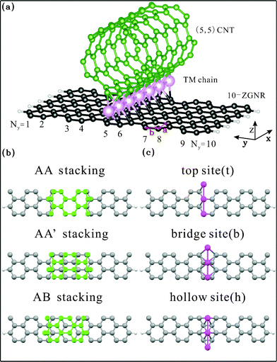 | ||
| Fig. 1 (a) (5,5) CNT on a 10-ZGNR coupled by a linear TM chain. Three stacked configurations (b) and three adsorption sites (c) are considered. | ||
A primitive unit cell includes forty carbon atoms, two hydrogen atoms, and a TM atom. There are three stacked configurations between the armchair CNT and zigzag GNR (Fig. 1(b)). In the AA stacking, C–C bonds from the bottom of the CNT are projected directly onto those at the center of the ribbon.28 However, if one atom of the CNT C–C bonds is projected onto a carbon atom, and another onto the center of a hexagon in the ribbon, the structure is called AB stacking, which is usually observed in bulk graphite. Fig. 1(b) also shows a new arrangement called AA'-stacking in which the CNT is shifted from the configuration of AA stacking by half a periodic length of the unit cell along the x-axis. Three adsorption sites for the TM chain are considered, as are shown in Fig. 1(c). The top site (t), bridge site (b), and hollow site (h) indicate the TM atom being directly above a C atom, over a C–C bond, and above the center of a hexagon, respectively. Two binding locations for the TM chain, at the ribbon center (between Ny = 5 and 6) and near the ribbon edge (between Ny = 8 and 9), are investigated.
Binding energy per TM atom (Eb) is calculated by subtracting the total energy of the coupled system from the sum of total energies of the isolated components, or Eb = [(ECNT + EGNR + Echain) − ECNT/chain/GNR]. As is indicated in Table 1, the AA-hh configuration, where the first (second) h indicates that the TM atom is at the hollow site of the CNT (GNR), is the most energetically favorable structure among the three listed configurations for binding at the ribbon center, with a strong binding energy of 3.666 eV. The other two configurations (AA'-hb and AB-ht) are almost equally robust, having only slightly smaller Eb (3.435 and 3.418 eV respectively), due in part to the relaxation process in our calculation. Compared with the binding energy of only 0.1127 eV for the same stacking of CNT and GNR without the Ti chain in previous study,21 binding energy for the Ti-mediated configuration is roughly fourteen times larger. This clearly shows how effectively the Ti chain “glues” the two carbon components together. When the CNT is placed near the ribbon edge, binding energy is even higher (3.814 eV for the AA-hh configuration). In fact all three configurations listed in Table 1 for edge binding have higher binding energies than their counterparts for the center binding. The overall picture is clearly that the strength of the composite structure of CNT and GNR is greatly enhanced by the introduction of the Ti chain. The exact binding energy depends on the stacked configuration and binding location.
| Binding location | Stacking configuration | Binding energy Eb (eV/TM atom) | Magnetic moment per unit cell Mtot (μB) |
|---|---|---|---|
| Ribbon center | AA-hh | 3.666 | 0.000 |
| AA'-hb | 3.435 | 0.000 | |
| AB-ht | 3.418 | 0.000 | |
| Ribbon edge | AA-hh | 3.814 | 0.240 |
| AA'-hb | 3.616 | 0.249 | |
| AB-ht | 3.601 | 0.249 |
Adsorption of a vanadium chain by aforementioned stacking structures is summarized in Table 2. All listed configurations also indicate that robust structures are formed as a result of the adsorbed V chain. The AA-hh remains the most stable for coupling at the ribbon center, but AB-th has the strongest coupling near the edge. Same as the Ti adsorption, coupling at the ribbon edge is also stronger than coupling at the center.
| Binding location | Stacking configuration | Binding energy Eb (eV/TM atom) | Magnetic moment per unit cell Mtot (μB) |
|---|---|---|---|
| Ribbon center | AA-hh | 3.484 | 0.209 |
| AB-th | 3.465 | 0.702 | |
| AA'-hb | 3.226 | 0.832 | |
| Ribbon edge | AB-th | 3.658 | 0.518 |
| AA-hh | 3.650 | 0.723 | |
| AA'-bh | 3.648 | 0.024 |
3 Low-energy electronic properties
An isolated (5,5) armchair CNT is a non-magnetic metal with two linear bands intersecting at the Fermi level, as shown in Fig. 2. Also shown in the same figure are energy bands for an isolated 10-ZGNR, which is antiferromagnetic and contains two largely flat bands approaching the Brillouin zone boundary, where edge states contributed by C atoms at the zigzag boundaries are dominant. Separated by an energy gap that is divided by the Fermi level, the two bands are each valence and conduction band respectively.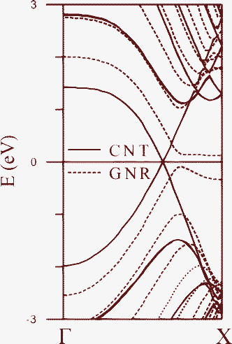 | ||
| Fig. 2 The bands of the isolated (5,5) CNT and 10-ZGNR with antiferromagnetic configuration. | ||
The large binding energies for the adsorption of Ti chain indicate strong hybridization between C 2p and Ti 3d orbitals. Gone are the CNT linear bands crossing the Fermi level. For center coupling, two configurations (AB-hb and AA'-ht) actually become semiconducting (Fig. 3(b) and 3(c)) with energy gaps around 0.2 eV, while the most energetically favorable AA-hh is metallic (Fig. 3(a)). The contribution of Ti 3d orbitals is mainly distributed in an energy range between −3 and 5 eV, as is shown in the total density of states (DOS, in units of eV per unit cell) and local projected density of states (in units of eV per atom) of Fig. 4, with the upper panels representing the states for the majority spin and lower panels states for the minority spin. Here the distinction between a metal (Fig. 4(a)) and a semiconductor (Fig. 4(b)) is also obvious. In addition, the DOS of edge C states from GNR lie around EF and are equal for both spins, resulting in spin degeneracy. The contribution of Ti 3d orbitals is further indicated by the size of open circles shown in Fig. 3. The highest occupied state is dominated by the Ti 3d orbitals whereas the lowest unoccupied one mainly comes from edge C 2pz orbitals. Net magnetic moment for each of the three configurations is zero, meaning that the Ti chain is non-magnetic and the GNR remains antiferromagnetic, which is clearly seen in the plot of spin density for the AA-hh configuration in Fig. 5(a).
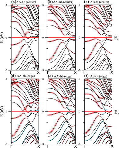 | ||
| Fig. 3 Band structures of the Ti chain-adsorbed configurations (a) AA-hh, (b) AA'-hb, and (c) AB-ht for ribbon center binding, as well as (d) AA-hh, (e) AA'-hb, and (f) AB-ht for ribbon edge binding. Solid black and blue curves represent electronic states of the majority and minority spins respectively. The size of each red circle is proportional to the contribution of the TM 3d orbitals. | ||
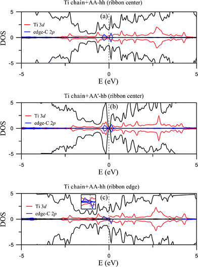 | ||
| Fig. 4 DOS of the Ti chain-adsorbed configurations AA-hh (a) and AA'-hb (b) for ribbon center coupling. (c) DOS of AA-hh for edge coupling. Total DOS are shown by solid black curves. Solid red and blue curves indicate projected DOS from the Ti 3d orbitals and 2pz orbitals of edge C atoms. | ||
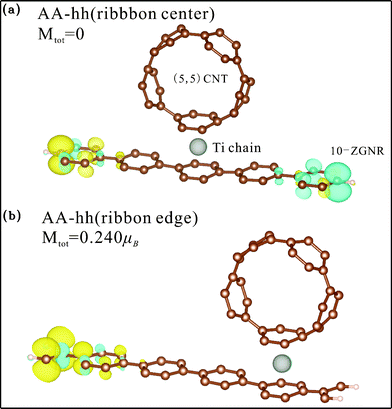 | ||
| Fig. 5 Spin density distribution of Ti chain-adsorbed AA-hh configuration for binding at (a) the ribbon center and (b) the ribbon edge. Yellow (blue) shade represents density of the majority (minority) spin. | ||
For coupling at the ribbon edge, hybridization leads to demagnetization of the C atoms on the binding side and magnetization on the other side, with the Ti chain remaining non-magnetic. Illustrated in Fig. 5 (b) is the spin density of the AA-hh configuration, which has a total magnetic moment of 0.240 μB per unit cell (Table 1). It clearly shows that the moment comes from the C atoms at the end opposite to the coupling side. The other two edge-coupling configurations have similar spin density but slightly larger moments. Energy bands (Fig. 3(d), 3(e), and 3(f)) indicate that all three configurations are metallic. It is also evident from the three figures that parts of the bands crossing the Fermi level are spin-polarized. DOS for AA-hh reveal that the source of this polarization comes from the edge C 2p orbitals (Fig. 4(c)).
Band structures for the adsorption of V chain are displayed in Fig. 6, with 6(a), 6(b), and 6(c) representing the three configurations for center binding and 6(d), 6(e) and 6(f) for those of edge binding. All right panels in the figures show the energy bands for the majority spin and left panels energy bands for the minority spin. Strong hybridization between C 2p and V 3d orbitals are easily seen and the sizes of open circles mark the contribution of V 3d orbitals. Their corresponding plots for DOS are shown in Fig. 7 and 8. Different from the adsorption of Ti chain, all six configurations are metallic and have quite complicated magnetic structures.
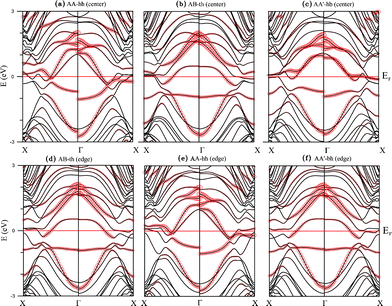 | ||
| Fig. 6 Band structures of the V chain-adsorbed configurations (a) AA-hh, (b) AB-th, and (c) AA'-hb for ribbon center coupling, as well as (d) AB-th, (e) AA-hh, and (f) AA'-bh for ribbon edge coupling. | ||
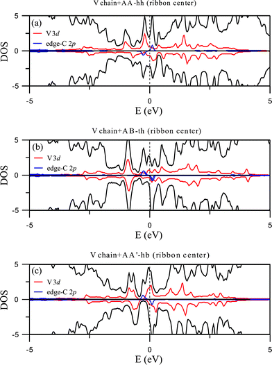 | ||
| Fig. 7 DOS of the V chain-adsorbed configurations at the ribbon center. | ||
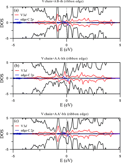 | ||
| Fig. 8 DOS of the V chain-adsorbed configurations at the ribbon edge. | ||
Contrary to the Ti chain, the adsorbed V chain is magnetic and therefore contributes to the magnetism of the whole structure. For coupling at the ribbon center (Fig. 9(a), 9(b), and 9(c)), the most energetically favorable AA-hh configuration has spin direction of the chain antiparallel to that of the edge C atoms, reducing the overall magnetic moment to 0.209 μB per unit cell. The other two configurations for center coupling, on the other hand, have the two spins in parallel and thus much larger magnetic moments (0.702 and 0.832 μB per unit cell respectively). For edge coupling, suppression of magnetism at the coupling side also occurs, but not as thoroughly as the case for the Ti chain. For either the AB-th or AA-hh configuration, the chain and the ribbon have the same spin direction (Fig. 10(a) and 10(b)) and thus larger total moment (0.518 or 0.723 μB per unit cell), while the AA'-bh has opposite spin directions and a negligible moment of 0.024 μB per unit cell (Fig. 10(c)).
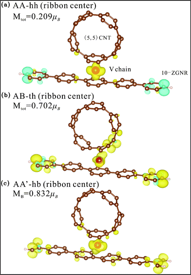 | ||
| Fig. 9 Spin density distribution of V chain-adsorbed configurations for ribbon center binding. Yellow (blue) shade represents density of the majority (minority) spin. | ||
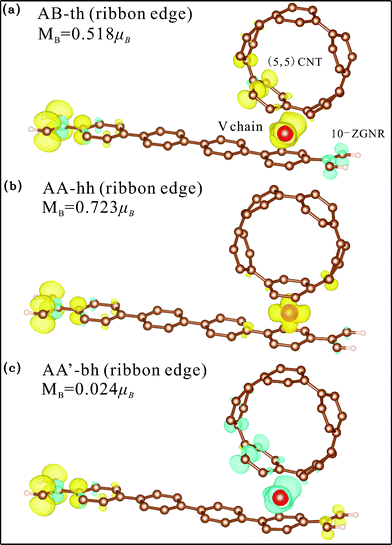 | ||
| Fig. 10 Spin density distribution of V chain-adsorbed configurations for ribbon edge binding. Yellow (blue) shade represents density of the majority (minority) spin. | ||
In summary, the C edge states contribute to magnetism of the pristine zigzag GNR. With a CNT and TM chain stacked near one of the edges, strong p–d hybridization and charge transfer between the 2p electrons of the edge C atoms and the 3d electrons of the TM atoms, either Ti or V, occurs, cancelling out spin polarization (completely for the case of Ti adsorption and partially for V) at the edge. The opposite edge is not affected. The Ti chain has no magnetic moment, but the V chain contributes to magnetism for the entire unit cell, with the overall moment decided by the relative spin directions of the V atom and edge C atoms.
4 Concluding remarks
We have shown that a Ti or V chain-mediated composite of CNT and GNR is a robust structure. Binding energy is large, especially for coupling near the ribbon edge. Most structures are metallic, except two configurations associated with Ti chain coupling at the ribbon center. Magnetic structures vary, ranging from non-magnetic to parallel and antiparallel directions of spins for the chain and ribbon. The results suggest a new method of synthesizing nanowires made of CNTs and transition metals over a GNR, which may be useful for application in nanoelectronic circuits.Acknowledgements
This work was supported by the National Science Council of the Republic of China under grant number NSC 98-2112-M-004-003-MY3. We are also grateful for support provided by the National Center for Theoretical Sciences and the National Center for High-performance Computing of the ROC.References
- K. S. Novoselov, A. K. Geim, S. V. Morozov, D. Jiang, Y. Zhang, S. V. Dubonos, I. V. Grigorieva and A. A. Firsov, Science, 2004, 306, 666 CrossRef CAS PubMed.
- C. Berger, Z. M. Song, T. B. Li, X. B. Li, A. Y. Ogbazghi, R. Feng, Z. T. Dai, A. N. Marchenkov, E. H. Conrad, P. N. First and W. A. de Heer, J. Phys. Chem. B, 2004, 108, 19912 CrossRef CAS.
- Y. Zhang, Y. W. Tan, H. L. Stormer and P. Kim, Nature, 2005, 438, 201 CrossRef CAS PubMed.
- K. S. Novoselov, E. McCann, S. V. Morozov, V. I. Fal'ko, M. I. Katsnelson, U. Zeitler, D. Jiang, F. Schedin and A. K. Geim, Nat. Phys., 2006, 2, 177 CrossRef.
- R. Saito, M. Fujita, G. Dresselhaus and M. S. Dresselhaus, Appl. Phys. Lett., 1992, 60, 2204 CrossRef CAS ; Phys. Rev. B: Condens. Matter, 1992, 46, 1804.
- T. W. Odom, J. L. Huang, P. Kim and C. M. Lieber, J. Phys. Chem. B, 2000, 104, 2794 CrossRef CAS.
- F. L. Shyu, C. P. Chang, R. B. Chen, C. W. Chiu and M. F. Lin, Phys. Rev. B: Condens. Matter, 2003, 67, 045405 CrossRef.
- L. C. Qin, Phys. Chem. Chem. Phys., 2007, 9, 31 RSC.
- K. Nakada, M. Fujita, G. Dresselhaus and M. S. Dresselhaus, Phys. Rev. B: Condens. Matter, 1996, 54, 17954 CrossRef CAS.
- M. Ezawa, Phys. Rev. B: Condens. Matter Mater. Phys., 2006, 73, 045432 CrossRef.
- Y.-W. Son, M. L. Cohen and S. G. Louie, Phys. Rev. Lett., 2003, 97, 216803 CrossRef PubMed.
- L. Yang, C.-H. Park, Y.-W. Son, M. L. Cohen and S. G. Louie, Phys. Rev. Lett., 2007, 99, 186801 CrossRef PubMed.
- S. Okada, Phys. Rev. B: Condens. Matter Mater. Phys., 2008, 77, 041408 CrossRef.
- Y.-W. Son, M. L. Cohen and S. G. Louie, Nature, 2006, 444, 347 CrossRef CAS PubMed.
- L. Pisani, J. A. Chan, B. Montanari and N. M. Harrison, Phys. Rev. B: Condens. Matter Mater. Phys., 2007, 75, 064418 CrossRef.
- A. Thess, R. Lee, P. Nikolaev, H. Dai, P. Petit, J. Robert, C. Xu, Y. H. Lee, S. G. Kim, A. G. Rinzler, D. T. Colbert, G. E. Scuseria, D. Tománek, J. E. Fischer and R. E. Smalley, Science, 1996, 273, 483 CAS.
- Y. H. Ho, C. P. Chang, F. L. Shyu, R. B. Chen, S. C. Chen and M. F. Lin, Carbon, 2004, 42, 3159 CrossRef CAS.
- S. Latil and L. Henrard, Phys. Rev. Lett., 2006, 97, 036803 CrossRef PubMed.
- M. F. Craciun, S. Russo, M. Yamamoto, J. B. Oostinga, A. F. Morpurgo and S. Tarucha, Nat. Nanotechnol., 2009, 4, 383 CrossRef CAS PubMed.
- D. Yu and L. Dai, J. Phys. Chem. Lett., 2010, 1, 467 CrossRef CAS.
- C. H. Lee, C. K. Yang, M. F. Lin, C. P. Chang and W. S. Su, Phys. Chem. Chem. Phys., 2011, 13, 3925 RSC.
- C. K. Yang, J. Zhao and J. P. Lu, Nano Lett., 2004, 4, 561 CrossRef CAS.
- E.-J. Kan, H. J. Xiang, J. Yang and J. G. Hou, J. Chem. Phys., 2007, 127, 164706 CrossRef PubMed.
- H. Sevinçli, M. Topsakal, E. Durgun and S. Ciraci, Phys. Rev. B: Condens. Matter Mater. Phys., 2008, 77, 195434 CrossRef.
- M. Koleini, M. Paulsson and M. Brandbyge, Phys. Rev. Lett., 2007, 98, 197202 CrossRef PubMed.
- G. Kresse and J. Furthmüller, Phys. Rev. B: Condens. Matter, 1996, 54, 11169 CrossRef CAS.
- G. Kresse and J. Furthmüller, Comput. Mater. Sci., 1996, 6, 15 CrossRef CAS.
- J.-K. Lee, S.-C. Lee, J.-P. Ahn, S.-C. Kim, J. I. B. Wilson and P. John, J. Chem. Phys., 2008, 129, 234709 CrossRef PubMed.
| This journal is © The Royal Society of Chemistry 2012 |
