Surface structuring of bi-component fibres with photoembossing
Mian
Dai
*a,
Ties M.
de Jong
a,
Carlos
Sánchez
b,
Olivier T.
Picot
c,
Dirk J.
Broer
a,
Ton
Peijs
ac and
Cees W. M.
Bastiaansen
ac
aFaculty of Chemical Engineering and Chemistry, Eindhoven University of Technology, P.O Box 513, 5600MB, Eindhoven, The Netherlands. E-mail: M.Dai@tue.nl; Fax: +31-40-243-6999; Tel: +31-40-247-3282
bInstituto de Ciencia de Materiales de Aragón (ICMA), CSIC-Universidad de Zaragoza, Departamento de Física de la Materia Condensada, Facultad de Ciencias. C./Pedro Cerbuna 12, 50009, Zaragoza, Spain
cSchool of Engineering and Materials Science, Queen Mary University of London, Mile End Road, London, E1 4NS, UK
First published on 11th September 2012
Abstract
A novel microstructuring technique, photoembossing, is used to create relief structures on the surface of fibres to generate new functionalities, such as diffractive optical effects for fashion design. A typical photopolymer compound, which consists of a polymeric binder, a multifunctional monomer and a photoinitiator is coated on the surface of a conventional synthetic core fibre (PET). Photoembossing is performed via a non-contact exposure to an interference pattern to obtain surface-relief gratings with the grating vector along the fibre axis. The monofilament fibres with grating structures perpendicular to the fibre axis were produced with a period of 1 and 8 μm and a typical height of 60–110 nm and 900–1300 nm, respectively. In accordance with the grating equation, it is observed that the micro-structured fibres with a pitch of 1 μm exhibit a strong angular dispersion and this in contrast to fibres with a pitch of 8 μm. Separated diffracted colours are observed predominantly in the first case (red, green and blue) by varying the viewing angle.
1. Introduction
New functionalities need to be introduced into fibres, wovens and non-wovens to extend their range of applications. Many of such functionalities can be obtained by integration of micro- and/or nano-structured surfaces into fibres and fabrics. For instance, microstructured fibres can be used as ultrafiltration membranes, carriers for catalysts, scaffolds for tissue engineering, fibre Bragg gratings, etc.1–6 Besides, angular-dependent optical effects based on diffraction of light can be potentially introduced in fibres by creating diffractive structures on their surface.7 The textiles produced from these fibres can be used for fashion design. Traditionally the micro- and/or- nano-structuring of fibres is performed using specific dye designs which yield a surface structure in a single dimension, i.e. grooves or lines along the fibre length.8 However, micro- and/or nano-structuring of fibres perpendicular to fibre axis (grooves or lines perpendicular to the fibre axis) is technologically far more difficult. At this moment, it is mainly performed via mechanical embossing of fibres.9,10 On the other hand, mechanical embossing of non-flat, strongly cured surfaces, such as encountered in fibres, is technologically difficult. Moreover, it is hard to produce micro-structured multifilament yarns and most methods are hard to implement in a high-speed spinning line. Consequently, a non-contact, micro- and/or nano-structuring technique for creating relief structures in fibres is in demand.Photoembossing is a novel technique to produce relief structures on the surface of fibres. One of the main advantages of photoembossing is that it generates micro- and/or nano- structures without etching procedures,11 which facilitates the incorporation of this process into a spinning line. The typical photopolymer mixture usually consists of a polymeric binder, a functional monomer and a photo-initiator, which is applied from solution to form a transparent solid thin film on the substrate.12–17 A patterned UV exposure is first applied to the photopolymer film using a photo-mask or interference holography to locally activate the photo-initiator and generate free radicals. The sample is then heated above the glass transition temperature to increase mobility and to start the polymerization. It causes a reaction driven diffusion of reactive species from non-exposed (low exposed) area to the exposed (high exposed) area. A flood exposure/a second heating step is applied to completely polymerize the relief structure.13–17 Various processing parameters influence the height and shape of the final relief structure, which include UV exposure dose, exposure time, development temperature, photopolymer blend composition, film thickness, etc.11,12,15,18 Most of these parameters show an optimum level above which the relief height decreases again or remains constant. Previously,19 it was shown that visco-elastic photopolymer mixtures can be generated and directly utilized to spin fibres. After spinning, the fibres were photoembossed using a mask exposure and relief structures were generated during a thermal development step. After a subsequent flood exposure, micro-structured monofilament, single component fibres were obtained. The fibres were very brittle and difficult to handle due to the presence of a densely crosslinked macromolecular network in the fibres.
In this paper, a bi-component fibre is prepared which consists of a polyester (PET) core fibre and a functional coating. A synthetic core fibre is employed to avoid brittleness of the fibre and to provide mechanical stability, while a thin photopolymer coating is applied to generate a diffractive grating structure on the surface of the fibre via photoembossing. After coating, the fibre is exposed to a holographic interference pattern, using two coherent UV beams, resulting in grating structures after the development step.20–23 Different grating spacings are simply obtained by changing the recording angle between the two interfering light beams. Previously, conventional fibre Bragg gratings were produced by using holographic techniques via continuous wavelength laser.3 But this is not compatible with the textile manufacture. In this paper, the interference holography is performed using a pulsed laser (4 ns pulse duration) which is expected to allow continuous spinning processes.24
2. Experimental
2.1 Materials
Poly(methyl methacrylate) (PMMA, Mw = 120 kg mol−1) was used as a polymeric binder and dipentaerythritol penta-/hexa-acrylate (DPPHA) as a multifunctional monomer. All materials were purchased from Sigma Aldrich (United States). Irgacure 369 was used as a photo-initiator and was obtained from CIBA Specialty Chemicals (Germany).PMMA photopolymer mixtures were prepared using 47.6 wt% of PMMA polymer, 47.6 wt % of DPPHA monomer and 4.8 wt% of Irgacure 369 and dissolved in propylene glycol methyl ether acetate (PGMEA) in a weight ratio of 1![[thin space (1/6-em)]](https://www.rsc.org/images/entities/char_2009.gif) :
:![[thin space (1/6-em)]](https://www.rsc.org/images/entities/char_2009.gif) 10.
10.
PET monofilaments were melt-spun using PET granulates (Mn: ∼18,500, MFI: ∼135 g/10min (280 °C, 2.16 kg), Tg: 79 °C, Tm: 258 °C, X%: 24%) received from Teijin and post-drawn to a draw ratio of 3–3.5 at ∼90 °C. The diameter of obtained PET monofilaments is ∼185 ± 15 μm.
2.2 Photoembossing via pulsed holography
The PET monofilaments were spray-coated using an air brush with the PMMA photopolymer solution. During the spraying, most of PGMEA solvents were removed under the high air pressure of the air brush and the fibres were also heated at 80 °C after each spray to evaporate the solvent. After spraying, the bi-component fibres were heated again at 80 °C for 20 min to remove the residual traces of solvent. To induce a grating structure on the surface of fibres, a pulsed Nd:Yag laser was coupled to second and third harmonic modules to emit 4 ns pulses of 355 nm linearly polarized light with vertical polarization. The laser beam was split into two equal intensity beams, which were subsequently combined to make an interference pattern on the substrate. The recording angle between the two interfering beams was 2.5° and 20.5°, which gave a grating period of ∼8 μm and ∼1 μm, respectively. The photopolymer fibres were fixed on a sealed hot-stage with an opening facing the interfering beams (see Scheme 1). The samples were on a hot-stage at 130 °C and subsequently exposed to a laser at that temperature.25 The exposure energies were optimized for respectively a grating period of 8 μm (exposure energy: ∼0.6 mJ cm−2) and for a grating period of 1 μm (exposure energy: ∼3.0 mJ cm−2). During the procedure, only the two ends of the fibres touched the hot-stage and the real temperature of the central part of the fibres could be lower than the temperature of hot-stage. After exposure, the fibres were kept at 130 °C for 10 min for thermal development.25 The obtained relief structures were chemically fixed by a flood exposure to a UV Exfo Mercury lamp for 10 min at room temperature.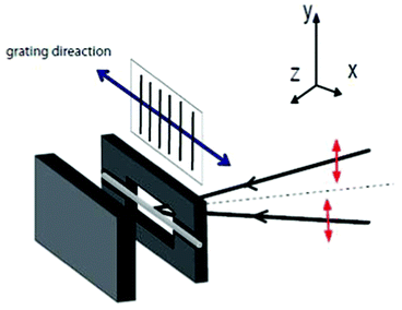 | ||
| Scheme 1 Schematic representation of the hot-stage set-up. | ||
2.2 Characterization
The investigation of the cross section and the surface-relief structure of the bi-component fibres were carried out using a FEI Quanta 3D Scanning Electron Microscope. To prevent charging in the electron beam, a thin gold layer was coated on the surfaces of fibres via vapour deposition. The height of the relief structure on the surface of the fibres was measured for each pitch of the gratings.Mechanical properties of the original PET fibres, annealed PET fibres, the coated PET fibres and the structured fibres were measured using a tensile tester Z010 (Zwick Co., Germany) at a speed of 0.1% strain per second. Here, for reference purposes, the PET fibres were post-annealed at 80 °C and 130 °C at a fixed length and cured using a UV lamp for 10 min at room temperature. The coated PET fibres were also post-annealed at 130 °C at a fixed length and cured using a UV lamp for 10 min at room temperature. Since the length of the grating structure on the surface of fibre is limited (<6 mm long), the gauge between the two clamps is ∼5 mm.
3. Optical Effects
The visual appearance of a micro-structured fibre is dependent on the wavelength of incident light and the angular selectivity of the grating structure. The anticipated effect is twofold: for a fixed angle of incidence, different wavelengths are diffracted into different viewing angles; on the other hand, different colours will be observed at a specific viewing angle when one changes the angle of incidence. In order to obtain the desired visual effects, it is crucial to choose the correct grating period for the structured fibre. In general, this is governed by the grating equation for both transmission and reflection, also for both curved surface and flat surface.26 Light incident on a grating is diffracted according to:| Λ(nmsinθm − ninsinθin) = mλ | (1) |
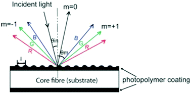 | ||
| Fig. 1 Sketch of a grating on the surface of a bi-component fibre. | ||
In order to obtain significant angular dispersion, i.e. clearly separated, distinct colours at different angles, a relatively small grating period is required (see Fig. 2a). In this paper we chose grating periods of 1 μm and 8 μm and compared the visual appearance of the resulting fibres. As shown in Fig. 2b, for a 1 μm period the visual spectrum (approximately 400–700 nm) is diffracted into a broad angular range (from a range 23.6°–44.4° for normal incident light up to a range of 44.4°–90° for an angle of incidence of 17.5°), resulting in angular separation between different colours. The 8 μm period results in much smaller diffraction angles (from a range 2.9°–5.0° for normal incident light up to a range of 74.3°–90° for an angle of incidence of 65.9°) and it is expected that the colour separation is too small to obtain the desired visual effect.
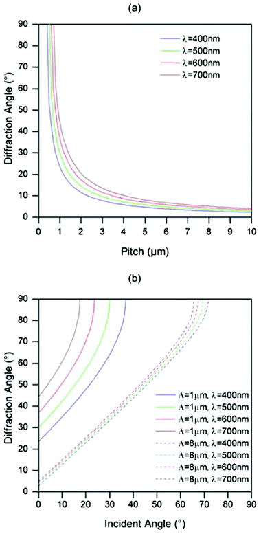 | ||
| Fig. 2 The calculated diffraction angle of the first order (m = +1) as a function of the grating period Λ (θin = 0°) (a) and as a function of the angle of incidence for Λ =1 μm and 8 μm (b), based on the grating equation. | ||
4. Results and discussion
A conventional melt-spun polyester (PET) monofilament was produced with a Young's modulus of approximately 4–8 GPa (see Table 1). For reference purposes, the fibres were post-annealed at a fixed length which increased the stiffness to 6–9 GPa (see Table 1), which is probably due to post-crystallization effects.27,28 Subsequently, a thin coating of the photopolymer mixture was applied to the monofilament fibres using a volatile solvent and an air brush. Typically, fibres with a core diameter of 185 ± 15 μm with a thin coating of the photopolymer (thickness: 12 ± 1 μm) were obtained. The coated PET fibre as a composite has a similar modulus of 6–9 GPa (see Table 1) as the post-annealed PET fibre. Apparently, the comparatively small fraction of cladding material does not influence the modulus of the coated fibre significantly if there is no grating structure in the bi-component fibre.| Sample | Original PET fibre | Annealeda PET fibre | Coated fibreb | Structured fibrec | |
|---|---|---|---|---|---|
| 8 μm | 1μm | ||||
| a For reference purposes, the PET fibres were post-annealed at 80 °C and 130 °C at a fixed length and cured using a UV lamp at RT. b For reference purposes, the coated PET fibres were also post-annealed at 130 °C at a fixed length and cured using a UV lamp at RT. c The fibres were photoembossed at 130 °C. | |||||
| Modulus (GPa) | 4–8 | 6–9 | 6–9 | 5–8 | 5–8 |
Photoembossing via interference pulsed holography was applied to the bi-component fibre. A grating structure is formed on the surface of the fibre. Within the experimental error, the structured PET fibre has the same modulus as the coated PET fibre without a relief structure (see Table 1). The grating structures on the fibres were investigated using scanning electron microscopy (SEM) and are shown in Fig. 3. A grating structure is formed on the exposed side of the bi-component fibre while no grating structure is found on the non-exposed side of the bi-component fibre. A fully structured fibre could be obtained by a multi exposure covering the whole fibre surface. The relief height depends on the processing conditions and grating period. For the grating structure of 8 μm, the relief height is, in the optimum conditions (see experimental part) approximately 900–1300 nm. For the grating structure of 1 μm, the relief height reached was 60–110 nm in the optimum conditions. The rather large scatter in the height of the relief structures is probably related to the inhomogeneities in the core fibre or coating.
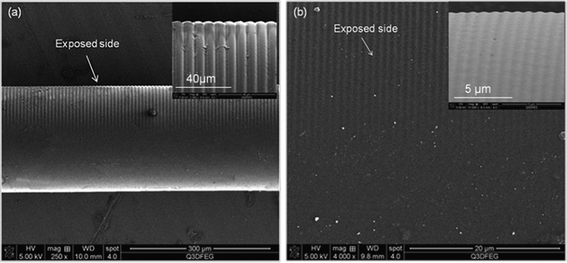 | ||
| Fig. 3 SEM images of the photoembossed bi-component fibre: a) Λ = 8 μm and (b) Λ =1 μm. | ||
As mentioned above, white-light is expected to be diffracted towards the viewer by the grating structure. It is found that the photoembossed fibre with surface grating structure of 1 μm exhibits a strong angular-dependent visual effect. The central part of the fibre with the relief structures shows separated colours (red, green and blue at different viewing angles), while the two ends of the fibre without grating structure are transparent (see Fig. 4). As expected, the fibres with a surface-relief grating with a pitch of 8 μm exhibit a certain visual effect, but the different diffraction colours at the slightly different viewing angles are hard to detect (see Fig. 5).
 | ||
| Fig. 4 Photographs of photoembossed fibre with surface grating structure of 1 μm. These images were taken at slightly different viewing angles under ambient light. | ||
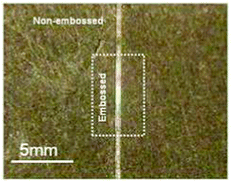 | ||
| Fig. 5 Photographs of photoembossed fibre with surface grating structure of 8 μm under ambient light. | ||
5. Conclusions
In this study, we demonstrated that the photoembossing technique could be used as a novel non-contact method to create diffractive gratings on the surfaces of fibres, which will be compatible with the fibre manufacture. To get high performance fibres with surface-relief gratings, the bi-component fibres were prepared by coating a high modulus core fibre with a functional photopolymer. A grating structure was created on the surface of the bi-component fibres which is perpendicular to fibre axis. Consequently, it is found that the fibres with a grating structure of 1 μm exhibit a strong angular-dependent visual effect. Separated diffracted colours (red, green, blue) are observed at different viewing angles. In contrast, the fibres with a grating structure of 8 μm exhibit different diffracted colours only at very slightly different viewing angles. The fabric/textile produced from these structured fibres can be used for fashion design.Acknowledgements
The research forms part of the research programme of the Dutch Polymer Institute (DPI), project #679. Funding from the Spanish MINECO project MAT2011-27978-C02-02, CSIC project i-LINK0394, Gobierno de Aragón, and FEDER (EU) is also acknowledged.References
- P. Z. Culfaz, E. Rolevink, C. Rijn, R. G. H. Lammertink and M. Wessling, J. Membr. Sci., 2010, 347, 32 CrossRef CAS.
- S. Megelski, J. S. Stephens, D. B. Chase and J. F. Rabolt, Macromolecules, 2002, 35, 8456 CrossRef CAS.
- K. O. Hill and G. Meltz, J. Lightwave Technol., 1997, 15, 1263 CrossRef CAS.
- D. Hussain, F. Loyal, A. Greiner and J. H. Wendorff, Polymer, 2010, 51, 3989 CrossRef CAS.
- T. Debeche, C. Marmet, L. Kiwi-Minsker, A. Renken and M. Juillerat, Enzyme Microb. Technol., 2005, 36, 911 CrossRef CAS.
- N. F. Hughes-Brittain, O. T. Picot, L. Qiu, C. Sanchez, T. Peijs and C. W. M. Bastiaansen, MRS Proceedings, 2012, 1418 Search PubMed.
- W. J. Shi and P. H. Zhang, Melliand China, 2008, 3, 28 Search PubMed.
- W. Nijdam, J. de Jong, C. J. M. van Rijn, T. Visser, L. Versteeg, G. Kapantaidakis, G.H. Koops and M. Wessing, J. Membr. Sci., 2005, 256, 209 CAS.
- M. Halbeisen and H. Schift, Chem. Fibres Int., 2004, 54, 378 CAS.
- H. Schift, M. Halbeisen, U. Schutz, B. Delahoche, K. Vogelsang and J. Gobrecht, Microelectron. Eng., 2006, 83, 855 CrossRef CAS.
- C. Sánchez, B. Gans, D. Kozodaev, A. Alexeev, M. J. Escuti, C. Heesch, T. Bel, U. S. Schubert, C. W. M. Bastiaansen and D. J. Broer, Adv. Mater., 2005, 17, 2567 CrossRef.
- K. Hermans, F. K. Wolf, J. Perelaer, R. A. J. Janssen, U. S. Schubert and C. W. M. Bastiaansen, Appl. Phys. Lett., 2007, 91, 1 CrossRef.
- K. Hermans, C. W. M. Bastiaansen, D. J. Broer and J. Perelaer, Int. Pat., WO 2008025508, 2008 Search PubMed.
- K. Hermans, M. Delden, C. W. M. Bastiaansen and D. J. Broer, J. Micromech. Microeng., 2008, 18, 1 CrossRef.
- K. Hermans, I. Tomatsu, M. Matecki, R. P. Sijbesma, C. W. M. Bastiaansen and D. J. Broer, Macromol. Chem. Phys., 2008, 209, 2094 CrossRef CAS.
- N. Adams, B. Gans, D. Kozodaev, C. Sanchez, C. W. M. Bastiaansen, D. J. Broer and U. S. Schubert, J. Comb. Chem., 2006, 8, 184 CrossRef CAS PubMed.
- B. Gans, C. Sánchez, D. Kozodaev, D. Wouters, A. Alexeev, M. J. Escuti, C. W. M. Bastiaansen, D. J. Broer and U. S. Schubert, J. Comb. Chem., 2006, 8, 228 CrossRef PubMed.
- K. Hermans, S. Z. Hamidi, A. B. Spoelstra, C. W. M. Bastiaansen and D. J. Broer, Appl. Opt., 2008, 47, 6512 CrossRef PubMed.
- M. Dai, O. T. Picot, N. F. Hughes-Brittain, T. Peijs and C. W. M. Bastiaansen, J. Mater. Chem., 2011, 21, 15527 RSC.
- C. M. W. Bastiaansen, D. J. Broer and C. Sánchez, Int. Pat, WO 2006085757A2, 2006 Search PubMed.
- D. Xia, Z. Ku, S. C. Lee and S. R. J. Bruek, Adv. Mater., 2011, 23, 147 CrossRef CAS PubMed.
- T. Zhai, X. Zhang, Z. Pang and F. Dou, Adv. Mater., 2011, 23, 1860 CrossRef CAS PubMed.
- S. R. J. Brueck, Proc. IEEE, 2005, 93, 1704 CrossRef CAS.
- O. T. Picot, R. Alcalá, C. Sánchez, M. Dai, N. F. Hughes-Brittain, D. J. Broer, T. Peijs and C. W. M. Bastiaansen, Macromol. Mater. Eng., 2012 DOI:10.1002/mame.201100433.
- N. F. Hughes-Brittain, O. T. Picot, M. Dai, T. Peijs and C. W. M. Bastiaansen, Appl. Surf. Sci., 2012, 158, 8609 CrossRef.
- E. Hecht, in Optics, Addison Wesley, San Francisco, CA, 2002, Ch. 10 Search PubMed.
- F. S. Smith and R. D. Steward, Polymer, 1974, 15, 283 CrossRef CAS.
- P. N. Peszkin and J. M. Schultz, J. Polym. Sci., 1986, 24, 2591 CrossRef CAS.
| This journal is © The Royal Society of Chemistry 2012 |
