Organophotocatalysis system of p/n bilayers for wide visible-light-induced molecular hydrogen evolution†
Toshiyuki
Abe
*a,
Junpei
Chiba
a,
Misaki
Ishidoya
a and
Keiji
Nagai
b
aDepartment of Frontier Materials Chemistry, Graduate School of Science and Technology, Hirosaki University, 3 Bunkyo-cho, Hirosaki 036-8561, Japan. E-mail: tabe@cc.hirosaki-u.ac.jp; Fax: +81 172 39 3580; Tel: +81 172 39 3580
bChemical Resources Laboratory, Tokyo Institute of Technology, Suzukake-dai, Midori-ku, Yokohama 226-8503, Japan
First published on 8th August 2012
Abstract
We developed a photocatalysis system composed of two types of organic p/n bilayers for the evolution of H2. When a bilayer of 29H,31H-phthalocyanine (H2Pc, a p-type semiconductor)/fullerene (C60, an n-type semiconductor) was applied to a photocatalyst by loading a Pt co-catalyst onto the C60 surface, the Pt-coated C60 surface induced H2 evolution, concurrently involving photocatalytic oxidation at H2Pc in the other bilayer. The photocatalytic reaction can occur along with photophysical events in the p/n interior. In order to draw out an efficient photocatalysis, the factors affecting H2 evolution were investigated in terms of the intensity of light irradiated, thickness of the bilayers, and the amount of Pt co-catalyst deposited. The organophotocatalysis system demonstrates a novel and advanced method of photocatalytic H2 evolution utilizing energy over the entire range of visible light.
Introduction
Molecular hydrogen (H2) is widely recognized as a potential clean energy source, and recently fuel cells have become practical devices for energy generation. Some fuel cells use H2, but a clean procedure for H2 production has not been established. Unless this problem is solved, a widespread public energy system that relies on the production and consumption of H2 cannot be created. Water photolysis is the most ideal method for producing H2. Since a photoelectrochemical approach for water splitting featuring a UV-responsive TiO2 photoanode was reported by Honda and Fujishima,1 the fabrication of inorganic semiconductor-based photocatalysts responsive to visible light has been passively conducted by means of band engineering (e.g. doping, solid solution, and the formation of a valence band alternative to O 2p orbitals for a more negative potential position).2–5 Although there is high demand for a visible-light-responsive photocatalyst that can achieve an efficient reaction of water, few examples of photocatalysts responsive to visible light with λ > 600 nm have been developed;6–9 that is, there are almost no instances of a wide visible-light-induced reaction of water. It should also be considered that the visible light response of the band-engineered photocatalysts may trade off its activities. Therefore, a new approach is needed to achieve efficient photocatalysis that utilizes a broad region of the visible light spectrum for facilitating the reaction of water in order to advance the development of photochemical energy conversion.We have previously demonstrated the novel function of organic p/n bilayers as photoelectrodes, particularly in the water phase,10–14 in which the bilayer can induce a chemical reaction at the solid/water interface along with photophysical events (i.e. light absorption, charge separation at the p/n interface, and carrier conduction) in its interior. Moreover, in the photoelectrodes of the p/n bilayer, the photoanodic and photocathodic effects can occur at the surface of the p-type and n-type conductors, respectively. Therefore, these studies prompted us to use the organic p/n bilayer as a photocatalyst. Here, we describe a photocatalysis system composed of two types of organic p/n bilayers set in a cell with twin compartments (Scheme 1), one of which is composed of 29H,31H-phthalocyanine (H2Pc, a p-type semiconductor)/fullerene (C60, an n-type semiconductor) for reduction and the other is a bilayer of 3,4,9,10-perylenetetracarboxylic-bis-benzimidazole (PTCBI, an n-type semiconductor)/H2Pc for oxidation. Although organic dyes have often been applied for the sensitisation of inorganic semiconductors,9,15–17 this system presents a novel example of light-induced H2 evolution by organophotocatalysis using dyes, and in particular, it utilizes the entire visible light region.
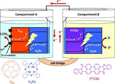 | ||
| Scheme 1 Schematic illustration of the photocatalysis system of H2Pc/C60 and PTCBI/H2Pc. | ||
Experimental
Chemicals
Pure C60 (>99.5%) was purchased from Tokyo Kasei Kogyo Co., Ltd. and used as received. PTCBI was synthesized and purified according to a previously described procedure.18 Commercially available H2Pc (Tokyo Kasei Co., Ltd.) was purified by sublimation prior to use. During sublimation, the exterior of the vessel was thermally controlled (temperature, 510 °C; pressure within the vessel, ∼1.0 × 10⁻² Pa). 2-Mercaptoethanol (RS−) was obtained from Kanto Chemical Co., Inc. The indium–tin oxide (ITO)-coated glass plate (sheet resistance, 8 Ω cm−2; transmittance, >85%; ITO thickness, 174 nm) was obtained from Asahi Glass Co., Ltd.Film preparation
The organic bilayers were prepared by vapour deposition (pressure, <1.0 × 10⁻³ Pa; deposition speed, ca. 0.03 nm s−1), for which an ITO-coated glass plate was used as base material. The bilayer of H2Pc/C60 comprised H2Pc coated on ITO, and C60 coated on top of the H2Pc layer (denoted as ITO/H2Pc/C60). To generate the PTCBI/H2Pc bilayer, PTCBI was first coated on ITO, followed by a coating of H2Pc (denoted as ITO/PTCBI/H2Pc). During vapour deposition, the temperature at the ITO plate was not controlled. Absorption spectral measurements were conducted using a Hitachi U-2010 spectrophotometer. The resulting absorption spectra of C60,19 PTCBI,20 and H2Pc (α-phase)20,21 were identical to those reported previously, and their absorption coefficients were used to determine the thickness of the film.13,14The deposition of Pt on ITO/H2Pc/C60 was carried out as follows: an electrochemical glass cell with a single compartment was equipped with a modified ITO working electrode (effective area, 1 cm2), a spiral Pt counter electrode, and an Ag/AgCl (in saturated KCl electrolyte solution) reference electrode. ITO/H2Pc/C60 was photocathodically polarized from +0.4 V to −0.2 V in acidic solution (pH = 2) containing 5.0 × 10⁻⁴ mol dm−3 H2PtCl6·6H2O. The product was denoted ITO/H2Pc/C60–Pt, wherein the amount of deposited Pt was controlled through the amount of charge passed (typically, 2.0 × 10⁻² C). This was performed using a potentiostat (Hokuto Denko, HA-301) with a function generator (Hokuto Denko, HB-104), a coulomb meter (Hokuto Denko, HF-201), and an X–Y recorder (GRAPHTEC, WX-4000) under illumination (light source, a halogen lamp; light intensity, ca. 100 mW cm−2). Irradiation was carried out from the back side of ITO-coated face.
The surface roughness of both C60 in the H2Pc/C60 bilayer (i) and Pt-coated C60 in the H2Pc/C60–Pt photocatalyst (ii) was measured by a laser microscope (Keyence, VK-9510). The roughness factor, calculated from the ratio of real surface area to geometrical area, was estimated to be ca. 2 and 2.3 in systems (i) and (ii), respectively.
Measurements
A cell with twin compartments separated by a salt bridge was used for the photocatalytic experiments (see Scheme 1). ITO/H2Pc/C60–Pt and ITO/PTCBI/H2Pc were placed in Compartments A and B, respectively, and the two photocatalyst devices were connected with a lead wire. The effective area of each photocatalyst device was 1 cm2 (1 cm × 1 cm). The photocatalytic study was carried out under an Ar atmosphere, where ITO/H2Pc/C60–Pt was immersed in a phosphoric acid solution (pH = 2) and ITO/PTCBI/H2Pc in an alkaline (KOH) solution containing a known concentration of thiol (pH = 11). For preparing the salt bridge, agar (1.3 g) and KNO3 (4.74 g) were first dissolved in hot water (1.0 × 10⁻² dm3), and then the mixture was allowed to flow into the bridging region of the cell (Scheme 1) and to solidify at room temperature. A halogen lamp was usually used as the light source, and irradiation was carried out from the Pt-coated C60 surface of the sample. For irradiation with monochromatic light, the lamp was used with a monochromator (Soma Optics, Ltd., S-10). A piece of shading board was placed between the two compartments to prevent the mixing of the light irradiated from distinct sources. The light intensity was measured using a power meter (type 3A from Ophir Japan, Ltd.). The produced H2 was analyzed using a thermal conductivity detector gas chromatograph (Shimadzu, GC-8A) equipped with a molecular sieve 5 Å column and Ar carrier gas. Quantification of H2 was performed using a chromatogram analyzer (Shimadzu, C-R8A) equipped with the chromatograph.Calculation methods
The external quantum efficiency (EQE) of H2 evolution was estimated as follows:| EQE = (NA × M)/(I × A) | (1) |
Results and discussion
The amount of H2 evolved in the photocatalysis system of ITO/H2Pc/C60 and ITO/PTCBI/H2Pc was determined and compared with four different control systems (Table 1). Under the reported conditions, the photocatalysis system generated 265.3 μl of H2 gas (Run 1). As negative controls, when only one of the two photocatalyst devices was irradiated (Runs 2 and 3), Pt was absent from the C60 surface (Run 4), or when no thiol was added in Compartment B (Run 5), virtually no H2 evolution in Compartment A was observed. Therefore, it appeared that the present photocatalysis system achieved reduction of H+ at the Pt-coated C60 surface of ITO/H2Pc/C60 (i.e. ITO/H2Pc/C60–Pt) and oxidation of thiol at the H2Pc/water interface of ITO/PTCBI/H2Pc.| System | H2 amount/μl | Note |
|---|---|---|
| a Photocatalysis occurs according to Scheme 1. The light intensity of 25 mW cm−2 was irradiated for each photocatalyst device, i.e. the sum of the intensities irradiated for ITO/H2Pc/C60–Pt (effective area, 1 cm2) and ITO/PTCBI/H2Pc (effective area, 1 cm2) was 50 mW cm−2. Irradiation was carried out from the Pt-coated C60 surface of the sample in Compartment A and the back side of ITO-coated face in Compartment B. Other conditions were as follows: irradiation time, 3 h; electrolyte solution in Compartment A, a phosphoric acid solution (pH = 2); electrolyte solution in Compartment B, an alkaline solution of 2-mercaptoethanol (concentration = 5 mmol dm−3, pH = 11); the amount of charge passed during Pt deposition, 2.0 × 10⁻² C; film thickness of the H2Pc/C60 bilayer, H2Pc = 75 nm and C60 = 125 nm and film thickness of the PTCBI/H2Pc bilayer, PTCBI = 300 nm and H2Pc = 60 nm. | ||
| Run 1 | 265.3 | Full conditionsa |
| Run 2 | 0 | Without irradiation for ITO/H2Pc/C60–Pt |
| Run 3 | 14.0 | Without irradiation for ITO/PTCBI/H2Pc |
| Run 4 | 1.0 | No deposition of Pt onto ITO/H2Pc/C60 |
| Run 5 | 0 | No addition of the electron donor (i.e. thiol) |
Based on the dependence of H2 generation on light intensity (Fig. 1) and thiol concentration (Fig. 2), the conditions for Run 1 are such that the evolution of H2 is the rate-limiting step. For intensities higher than 2.5 mW cm−2 in Fig. 1, the amount of H2 evolved was not proportional to light intensity, indicating that the generation of carriers was not the rate-determining step under these conditions. At concentrations higher than 5 mM (Fig. 2), the amount of H2 was not proportional to thiol concentration, which indicates that the overall kinetics of the photocatalysis system was not dominated by the oxidation of thiol under these conditions.
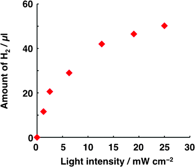 | ||
| Fig. 1 Dependence of the amount of H2 generated on light intensity. The conditions for Run 1 listed in Table 1 were applied to the photocatalysis system, with the exception that the irradiation time (30 min) and the intensity of white light used to irradiate ITO/H2Pc/C60–Pt were varied. Light of constant intensity (25 mW cm−2) was used to irradiate ITO/PTCBI/H2Pc. | ||
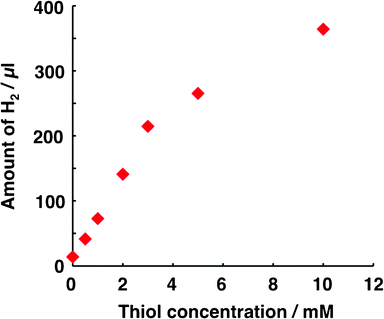 | ||
| Fig. 2 Dependence of the amount of H2 generated on thiol concentration. The conditions for Run 1 in Table 1 were applied to the photocatalysis system, with the exception that the thiol concentration in compartment B was varied. | ||
In addition to light intensity and thiol concentration, the dependence of H2 generation on the film thickness of H2Pc/C60 (Fig. 3) and the amount of Pt co-catalyst (Fig. 4) was also considered. By holding the thickness of C60 (i.e. 125 nm) and varying the thickness of H2Pc, the optimum H2Pc thickness was found to be 75 nm (Fig. 3a), indicating that a thick layer of H2Pc was effective for carrier generation. However, in the thicker H2Pc, an increase in electron–hole concentration can occur. On that occasion, electron–hole recombination becomes more probable with an increase in the concentration, thus resulting in a decrease in H2 evolution. Similarly, the optimum thickness of the C60 layer was investigated by holding the thickness of H2Pc constant at 75 nm and varying the C60 thickness (Fig. 3b). This experiment also indicated that a thick layer of C60 was most effective. However, a thicker C60 layer may induce an optical filter effect, disturbing the light absorption of H2Pc as well as C60 next to the p/n interface, thus leading to lower H2 evolution. The amount of H2 generated increased with the amount of Pt deposited up to 0.02 C (Fig. 4). When the loading of the co-catalyst is effective for the rate-limiting reaction, the H2 amount essentially increases. However, since the number of electrons photogenerated in the H2Pc/C60–Pt film is constant under the experimental conditions employed in the experiment reported in Fig. 4, an increase in the number of catalysis sites may cause a decrease in the activity per co-catalyst (i.e. decreasing the concentration of electrons at the co-catalyst), thus resulting in a decrease in H2 generation. Therefore, Fig. 4 may imply that the positive and negative factors for H2 evolution are balanced, particularly when the charge passed during Pt deposition is 0.04 C. Furthermore, the relatively higher loading of Pt caused a conspicuous depression of the amount of H2 generated. In consideration of the direction of irradiation (vide supra), an interruption of incident light by Pt may also contribute to the decrease in the amount of H2 generated. Considering the above-mentioned parameters, the results suggest that Run 1 was conducted under virtually optimal conditions.
![Dependence of the amount of H2 generated on film thickness of H2Pc/C60. The conditions for Run 1 in Table 1 were applied to the photocatalysis system, with the exception that the thickness was varied. Concretely, this study was conducted by changing the thickness of only one layer [e.g. H2Pc (a) or C60 (b)] in the bilayer.](/image/article/2012/RA/c2ra21281a/c2ra21281a-f3.gif) | ||
| Fig. 3 Dependence of the amount of H2 generated on film thickness of H2Pc/C60. The conditions for Run 1 in Table 1 were applied to the photocatalysis system, with the exception that the thickness was varied. Concretely, this study was conducted by changing the thickness of only one layer [e.g. H2Pc (a) or C60 (b)] in the bilayer. | ||
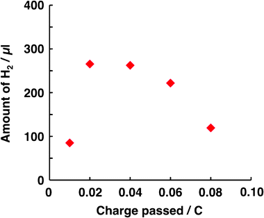 | ||
| Fig. 4 Dependence of the amount of H2 generated on that of Pt coated on the C60 surface. The conditions for Run 1 in Table 1 were applied to the photocatalysis system, with the exception that the Pt amount was varied. In all cases studied, the faradaic efficiency for Pt deposition was calculated as ca. 70% (i.e. during photocathodic polarization for depositing Pt, the reduction of H+ to H2 concurrently occurred with ca. 30% of the faradaic efficiency). | ||
Photocatalytic H2 evolution was also investigated under irradiation with monochromatic light. The EQE of H2 evolution was estimated for each of the incident wavelengths tested, and the results are shown in Fig. 5. The dependence of EQE on the incident wavelength was rather consistent with the sum of the absorption spectra of the bilayers employed (the spectrum of each bilayer is shown in ESI† (Fig. S1)). Furthermore, note that all visible light at λ < 750 nm contributed to H2 evolution.
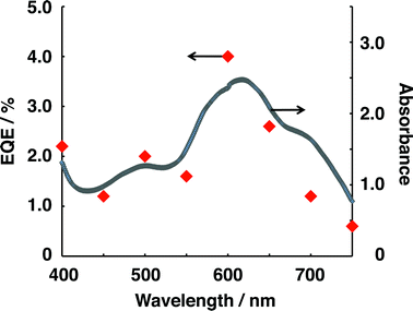 | ||
| Fig. 5 Dependence of EQE on the incident wavelength for the photocatalysis system and the sum of the absorption spectra of H2Pc/C60 and PTCBI/H2Pc. For measuring EQE, the conditions of Run 1 in Table 1 were applied to the photocatalysis system, with the exception that monochromatic light was irradiated for each photocatalyst device. The intensity irradiated for a photocatalyst device was 0.83 mW cm−2. | ||
A prolonged study was conducted in which the ITO/H2Pc/C60–Pt photocatalyst device was repeatedly used to test its durable performance for H2 generation. The conditions for this study were chosen based on the optimal experimental conditions found in the experiments, as shown in Fig. 1–4. Fig. 6 shows the relationship between the amount of H2 generated and the cycle number, explicitly demonstrating that stable photocatalysis for H2 evolution at ITO/H2Pc/C60–Pt occurred even after several cycles.
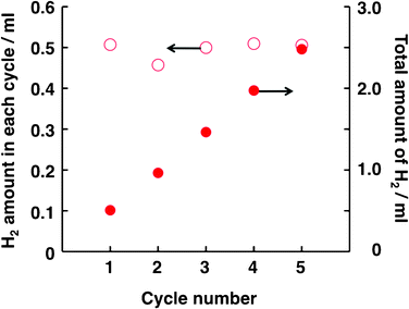 | ||
| Fig. 6 A prolonged study of photocatalytic H2 evolution in the present system. The conditions of Run 1 in Table 1 were applied to the photocatalysis system, with the exception that the charge passed during Pt deposition (4.0 × 10⁻² C) and the irradiation time (6 h in one cycle) were varied. In every cycle, the electrolyte solutions in both compartments were replaced with fresh solutions. | ||
The mechanism of photocatalytic H2 evolution at ITO/H2Pc/C60–Pt is suggested as follows: the fundamental characteristics of ITO/PTCBI/H2Pc and ITO/H2Pc/C60–Pt have been characterized by means of photoelectrochemistry,13,14 through which we confirmed that each bilayer can generate photovoltage in the p/n interior even when applied to a photoelectrode in the water phase. This supports the suggestion that the photophysical events in the bilayer are almost similar to those of the corresponding photovoltaic cell in the dry state.22 However, particularly for ITO/PTCBI/H2Pc in the water phase, carriers can be generated only from the exciton of PTCBI through charge separation at the p/n interface,10,13 which was also supported by the previous study of photoluminescence quenching of PTCBI by H2Pc.23 Thus, in Compartment B, the oxidizing power of the photogenerated holes can be consumed at the H2Pc/water interface,13 leading to the oxidation of thiol (the formal potential of H2Pc+/H2Pc = +0.70 V vs. Ag/AgCl;13 the oxidation potential of thiol = +0.60 V vs. Ag/AgCl24). In Compartment A (ITO/H2Pc/C60–Pt), the formation of the C602− active species can occur under irradiation, which has been confirmed by means of in situ spectroelectrochemistry.14 Local accumulation of the C602− species at the solid/water interface produces power for H+ reduction, resulting in the evolution of H2 (the formal potential of H+/H2 (pH = 2) = −0.32 V vs. Ag/AgCl). The potential of the electron-photodoped PTCBI in ITO/PTCBI/H2Pc is more negative than that of the hole-photodoped H2Pc in ITO/H2Pc/C60–Pt (i.e. the reduction potential of PTCBI/PTCBI− = ∼0 V vs. Ag/AgCl13). Therefore, the hole-photodoped H2Pc (H2Pc+) can be converted back to H2Pc by the electron transferred from the PTCBI layer via a connecting wire.
Conclusions
In summary, we have demonstrated a novel photocatalysis system in which the evolution of H2 can be induced by organic p/n bilayers responsive to the entire spectrum of visible light. Some examples of two-step excitation photocatalysis systems (λ < ∼550 nm) have been reported in which both inorganic semiconductor photocatalysts were coupled with an electron relay system;25–28 however, these are distinct from the present system in terms of the type of material, the structure of the photocatalysis system, and the range of visible light energy available to the photocatalytic reaction. Furthermore, considering the latter point, the present system is also distinct from the metal-free photocatalyst capable of H2 production (photocatalysis response: λ < 550 nm) recently reported by Wang and Domen.29 The efficiency of our photocatalyst system was compared with that of the reported visible- light photocatalyst systems for H2 evolution in terms of EQE (Table S1 in the ESI†). These results also support the sugestion that the Pt-loaded H2Pc/C60 is a novel and advanced photocatalyst capable of H2 evolution utilizing the entire visible light energy, because most of the reported EQE values were estimated in the near-UV region. Organic semiconductors offer easy processing and abundant variety for gaining better features of photocatalyst devices. As an example, the combination of an adsorbent (e.g. Nafion) with the PTCBI/H2Pc bilayer was recently reported to afford efficient photocatalysis for the decomposition of a typical odorous compound, trimethylamine (ca. 40% of EQE for CO2 formation).30 Organophotocatalysts can be expected to open new avenues in the fields of photo/chemical energy conversion and large-scale photocatalysis, thus leading to innovative technology towards applications in interior living space as well as in the water phase.Acknowledgements
This work was partly supported by a grant for Hirosaki University Institutional Research and a Grant-in-Aid for Scientific Research (T. A.) from the Ministry of Education, Culture, Sports, Science and Technology, Japan. We thank Dr Seiji Kakuta (Aomori Prefectural Industrial Technology Research Center) for the measurement of surface roughness.References
- A. Fujishima and K. Honda, Nature, 1972, 238, 37 CrossRef CAS.
- X. Chen, S. Shen, L. Guo and S. S. Mao, Chem. Rev., 2010, 110, 6503 CrossRef CAS.
- C.-C. Hu, Y.-L. Lee and H. Teng, J. Phys. Chem. C, 2011, 115, 2805 CAS.
- J. Wang, B. Huang, Z. Wang, P. Wang, H. Cheng, Z. Zheng, X. Qin, X. Zhang, Y. Dai and M.-H. Whangbo, J. Mater. Chem., 2011, 21, 4562 RSC.
- F. Zhang, K. Maeda, T. Takata and K. Domen, Chem. Commun., 2010, 46, 7313 RSC.
- X. Qiu, M. Miyauchi, H. Yu, H. Irie and K. Hashimoto, J. Am. Chem. Soc., 2010, 132, 15259 CrossRef CAS.
- S. Ikeda, T. Nakamura, T. Harada and M. Matsumura, Phys. Chem. Chem. Phys., 2010, 12, 13943 RSC.
- H. Kaga, K. Saito and A. Kudo, Chem. Commun., 2010, 46, 3779 RSC.
- R. Abe, K. Shinmei, K. Hara and B. Ohtani, Chem. Commun., 2009, 3577 RSC.
- T. Abe, K. Nagai, M. Kaneko, T. Okubo, K. Sekimoto, A. Tajiri and T. Norimatsu, ChemPhysChem, 2004, 5, 716 CrossRef CAS.
- T. Abe, K. Nagai, S. Kabutomori, M. Kaneko, A. Tajiri and T. Norimatsu, Angew. Chem., Int. Ed., 2006, 45, 2778 CrossRef CAS.
- T. Abe and K. Nagai, Org. Electron., 2007, 8, 262 CrossRef CAS.
- T. Abe, S. Miyakushi, K. Nagai and T. Norimatsu, Phys. Chem. Chem. Phys., 2008, 10, 1562 RSC.
- T. Abe, S. Tobinai, N. Taira, J. Chiba, T. Itoh and K. Nagai, J. Phys. Chem. C, 2011, 115, 7701 CAS.
- T. Shimidzu, T. Iyoda and Y. Koide, J. Am. Chem. Soc., 1985, 107, 35 CrossRef CAS.
- R. Abe, K. Sayama and H. Arakawa, Chem. Phys. Lett., 2003, 379, 230 CrossRef CAS.
- Q. Li, Z. Jin, Z. Peng, Y. Li, S. Li and G. Lu, J. Phys. Chem. C, 2007, 111, 8237 CAS.
- T. Maki and H. Hashimoto, Bull. Chem. Soc. Jpn., 1952, 25, 411 CrossRef CAS.
- A. Capobianchi and M. Tucci, Thin Solid Films, 2004, 33, 451–452 Search PubMed.
- T. Morikawa, C. Adachi, T. Tsutsui and S. Saito, Nippon Kagaku Kaishi, 1990, 962–967 CrossRef CAS.
- J. H. Sharp and M. Lardon, J. Phys. Chem., 1968, 72, 3230 CrossRef CAS.
- K. Suemori, T. Miyata, M. Yokoyama and M. Hiramoto, Appl. Phys. Lett., 2004, 85, 6269–6271 CrossRef CAS.
- K. Nagai, Y. Fujimoto, H. Shiroishi, M. Kaneko, T. Norimatsu and T. Yamanaka, Chem. Lett., 2001, 354 CrossRef CAS.
- S. Surdhar and D. A. Armstrong, J. Phys. Chem., 1986, 90, 5915 CrossRef.
- K. Tennakone and S. Wickramanayake, J. Chem. Soc., Faraday Trans. 2, 1986, 82, 1475 RSC.
- K. Sayama, R. Yoshida, H. Kusama, K. Okabe, Y. Abe and H. Arakawa, Chem. Phys. Lett., 1997, 277, 387 CrossRef CAS.
- Y. Sasaki, H. Nemoto, K. Saito and A. Kudo, J. Phys. Chem. C, 2009, 113, 17536 CAS.
- K. Maeda, R. Abe and K. Domen, J. Phys. Chem. C, 2011, 115, 3057 CAS.
- X. Wang, K. Maeda, A. Thomas, K. Takanabe, G. Xin, J. M. Carlsson, K. Domen and M. Antonietti, Nat. Mater., 2009, 8, 76 CrossRef CAS.
- K. Nagai, T. Abe, Y. Kaneyasu, Y. Yasuda, I. Kimishima, T. Iyoda and H. Imaya, ChemSusChem, 2011, 4, 727 CrossRef CAS.
Footnote |
| † Electronic supplementary information (ESI) available: Absorption spectra of H2Pc/C60 and PTCBI/H2Pc bilayers, and a list of efficiencies of visible light photocatalysts for H2 evolution. See DOI: 10.1039/c2ra21281a |
| This journal is © The Royal Society of Chemistry 2012 |
